Warco BH600G Saddle and Cross-slide power feed

Advert

Warco BH600G Saddle and Cross-slide power feed

Home Forums Manual machine tools Warco BH600G Saddle and Cross-slide power feed

Viewing 20 posts - 1 through 20 (of 20 total)
  • Author
    Posts
  • #12302
    OuBallie
    Participant
      @ouballie

      External motor for Feed Rod

      Advert
      #154199
      OuBallie
      Participant
        @ouballie

        Having completed my tool organising, I am now ready to replace those gears I mangled in my lathe – See 'I screwed up' thread.

        I thought I had unbent the shaft, but not fully on use, and in any case all the remaining teeth on that bronze worm gear finally gave way resulting in no power feed to Saddle or Cross-slide.

        As mentioned in one of my previous posts, I find that the Gearbox controlled speed to the Feed Rod just not slow enough when I want an almost ground finish.

        I can achieve that finish on short pieces of work by manual feed.

        Before I replace the parts, does anyone have any idea of what size motor I should use to power the Feed Rod?

        Speed control plus forward/reverse naturally.

        Geoff – watered plants then unblocked hand basin drain. Yuck.

        #154566
        OuBallie
        Participant
          @ouballie

          Went to measure the rpm of both Spindle and Feed Rod, but found all the headstock bearing oil had leaked from the two Sight Glasses so tried a different repair.

          The first repair involved fitting new O-rings, that have hardened in less than a year.

          Will do a separate thread if leaks cured.

          Below are the Spindle and associated Feed Rod RPMs;

          Gearbox – Position E and 112tpi
          Spindle – 2000rpm
          Feed Rod – 25/27rpm
          Spindle – 1500rpm
          Feed Rod – 20/24rpm
          Spindle – 1000rpm
          Feed Rod – 12/13rpm
          Spindle – 500rpm
          Feed Rod – 6/7rpm
          Spindle – 250rpm
          Feed Rod – 3rpm

          Would one of the12v 100rpm DC high torque motors geared/non-geared work, connected either directly to or via pulleys to the Feed Rod. There is a speed controller with For/Rev switch on eBay, from China of course, with suitable PC PSUs from UK vendors.

          Suggestions please.

          I do have that TECO motor I thought of using on the shaper, and I could nobble a VFD form one of the millers, but that seems overkill.

          Geoff – Wonder what the next project will be to add to the list, as if that list isn't long enough.

          #154622
          Lathejack
          Participant
            @lathejack

            Hello Geoff.

            The Warco BH 600 does have a rather corse longitudinal fine feed rate, from memory I think it is just under 5 thou, or to be exact about 0.0047 inches / spindle revolution on the finest setting. This is about twice as fast as the norm for a general purpose workshop lathe.

            I have a Warco 1330 lathe and with the standard screw cutting change wheels fitted the finest feed rate possible is also around 5 thou. To get round this these lathes come supplied and fitted with an extra set of change wheels which give 0.0026 inches / spindle revolution. But when these are fitted screw cutting cannot be done which is just daft.

            Because of this and problems with a poor finish in the form of banding on the work piece I also planned to fit a motor to power the apron feeds. I have a couple of Swedish made Electrolux motors with geared reduction from mig welder wire feed drives. These are variable speed 24 volts and have plenty of torque. They are fitted to the industrial mig welders we use at work and last many years without trouble.

            The plan was to fit them directly to the apron with a short feed rod made to replace the original, or bolt them to the end of the bed casting and drive the original feed rod from there with it disengaged from the gearbox but still supported there.

            In the end I fixed the cause of the banding problem, as detailed in one of my photo albums, and worked out a way of generating fine feed rates while retaining screw cutting using a 96 tooth gear on the gearbox input shaft. This replaces the 100 tooth gear used for fine feeds, and the 48 tooth gear used for most of the imperial threads. I still might fit the motor one day though.

            Hope this is of some use.

            #154627
            Bazyle
            Participant
              @bazyle

              **LINK**

              near the bottom of this link is the GH solution. Unfortunately his pictures are all rather small but otherwise a good website.

              However in view of your previous problem a drive based on a a battery drill/driver including the adjustable torque clutch would be an advantage.

              Edited By Bazyle on 06/06/2014 21:54:22

              #154628
              Gray62
              Participant
                @gray62

                Hi lathejack, where did you get the 96 tooth gear from?

                Regards

                Graeme

                #154630
                Lathejack
                Participant
                  @lathejack

                  Hello Graeme.

                  I have made a gear blank ready for cutting the teeth, but have since seen one listed in the catalogue of a gear cutting company, I am sure it was HPC Gears, I will try and find the catalogue and check.

                  #154634
                  GoCreate
                  Participant
                    @gocreate

                    Hi

                    Similar to Bazyle's link, I fitted 2 stepped belts via 4 stepped pulley's bypassing all the gears and giving about a 2:1 reduction which has proven to be a huge advantage for surface finish.. For screw cutting it takes only seconds to remove the belts and engage the gears.

                    A worthwhile benefit was the reduction in noise, the belts run very quite as compared to the gears. The dis-advantage of my set up is that, because the gear tumbler reverse is by-passed by the belts, my longitudinal feed is only towards the chuck and cross feed only inwards, I have not found this any real problem, if power feed in the other directions is needed then the belts have to be removed and gears engaged.

                    Nigel

                    #154833
                    OuBallie
                    Participant
                      @ouballie

                      Thanks for all the responses.

                      I have a battery drill I can experiment with, so Apron off shortly.

                      Best way I think is to modify the Tailstock end of the Feed Rod to take an extension to allow easy experimenting.

                      Will post once I start.

                      Geoff – Garage was wonderfully cool yesterday at19°C, outside touching 27°

                      #154839
                      Windy
                      Participant
                        @windy30762

                        On my early BH 600 I was given an ex arc euro power feed for a mill that I fitted on the tailstock end of the drive shaft as a test it is still there.

                        Very good for fine feed on direct drive but needs gearing down on back-gear.

                        Another project for the future.

                        #160690
                        OuBallie
                        Participant
                          @ouballie

                          BH600G FeedRod MotorUpdate!

                          I have at last made a start at fitting the battery drill as suggested by Bazyle, in conjunction with an Angle drive.

                          New Album added.

                          Advise needed please on the connection between the FeedRod and L-Drive shaft.

                          As can be seen the connection is only 5.7mm hidden inside the Rod End Cap, and I'm not too happy with this.

                          Was thinking of drilling the end of the FeedRod to take an extension piece, extending it past the Rod End Cap, thus giving more depth for the L-Drive shaft as well as more choice of using different motors if needed..

                          I need for sort this out, as the FeedRod with Worm Gear and Key can only be assembled together with ease whilst the Apron is off of the lathe.

                          Thinking cap on, and the following solution came to mind; Secure the extension piece using a roll pin that can of course be easily knocked out once the FeedRod is slid sideways, when it's roll pin, at the Gearbox end, is removed.

                          Geoff – Hope this makes sense, as it's past the time for my 40 winks

                          #160691
                          graham howe
                          Participant
                            @grahamhowe83128

                            Hi Geoff

                            I have just (in the last week) completed a new fine feed mechanism for the BH600G. It is based on my previous belt drive which provided quiet operation and this latest version builds on that but now adds a drive to the gearbox using three gears. The result is a fine feed reduced from 0.0047 to 0017 which is a lot better than the original. I have not yet produced any drawings but it is a simple design using stock gears if you cannot make your own.

                            see link: http://www.homepages.mcb.net/howe/fine%20feed.htm

                            #160744
                            graham howe
                            Participant
                              @grahamhowe83128

                              just updated the web site (new look and can be viewed on small screen devices) and the new link for this is now

                              http://www.homepages.mcb.net/howe/project%20fine%20feed.htm

                              #160757
                              Bazyle
                              Participant
                                @bazyle

                                Perhaps you could drill the shaft and put a couple of internal keyways in. Then put a pin throgh the motor shaft to engage, all slightly loose to give a degree of flexibility. Slightly more elegant than the even easier sawn slot across the end. When I mentioned a drill it was just the sprung clutch I was thinking of not the drill motor. Will it have the right speed torque range, and if running slow think about cooling too.

                                GH, Nice improvement to the belt drive feed. Well worth considering for a number of lathes. (are you being charged by the pixel? I'd still appreciate bigger pics face 12.)

                                #160768
                                graham howe
                                Participant
                                  @grahamhowe83128

                                  re Baztle

                                  No pay for pixels just hate taking my SLR into the workshop. I have just reorganised the whole site to cater for desktop, tablet & mobile screen sizes – a big job and photos are the last consideration atm. I do accept the currently ones are rubbish but this from a cheapo digi just to get the web page up so hopefully in future they will be updated!

                                  The belt drive feed improvement has turned out better than expected as it was just an excuse to test out the Sunderland gear machine. Now that some mods have been done and I have learnt how to set up the thing up correctly it isproducing near perfect involute curves specific to the number of teeth on the gear. This project will be the next update to the web site and hopefully the pdf's for operating and design will be get sorted (50% done). The drawings are another matter as they need updates but with 140 A4 sheets it is quite some project.

                                  regards Graham

                                  #160807
                                  Howard Lewis
                                  Participant
                                    @howardlewis46836

                                    The lowest standard feed/rev for a BH600, (and for the BH900, Chester Craftsman etc presumably) is 0.0047inch.

                                    On mine, I reduced this by replacing the 40T input gear to the Norton box, with a 80T one.

                                    (The cutter used to cut the gear was a No.7, Mod 1.25, 20PA , and a Peter Robinson Slotting Attachment to cut the keyway. Casting from College Engineering Supply, other material from stock, and now on a raising block to suit the BH600)

                                    As you might guess, the new gear would not fit because of the stud used to close the gear cover, so the the gear cover closure needs to be repositioned. Removing the securing "nut" from the Gear Cover resulted in the destruction of the Bakelite/Composite knob. Fortunately a suitable replacement was available, otherwise a knurled aluminium item would have been the end result.

                                    The counterpart to this, entailed the stud being removed and repositioned in the rear of the Headstock, after the gear cover had been redrilled in a position that cleared the new gear.

                                    Moving the securing "nut" from the gear cover resulted in the Bakelite/Composite knob being destroyed. Fortunately a replacement was available, or the end result would have been a knurled aluminium one!

                                    When all this was completed, I calculated that with the 120/127T compound gear suitably arranged, the finest feed obtainable was now 0.0022"/rev.. Using a tipped tool with a 0.005" cut, at minimum speed, lubricated with neat cutting oil, an extremely fine surface finish can be obtained when facing Mild Steel.

                                    A 1:1 tooth belt drive off the 120/127T compound gear should produce a feed rate of 0.0016"/rev., or 0.0015"/rev with a gear train of 40/127/120, and the 1:1 belt drive. AS long as it all fits inside the gear cover!

                                    As has already been said, an even finer feed could be obtained by using extra gears, (and a spindle), to compound the gear train, (or an epicyclic cluster?) but I am lazy and looked for what seemed to be the easy way at the time!

                                    Howard

                                    #173505
                                    OuBallie
                                    Participant
                                      @ouballie

                                      Four months side-tracked!

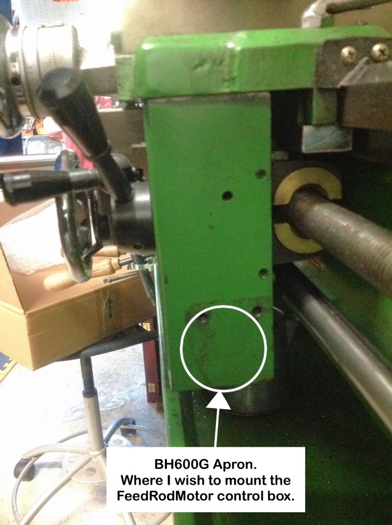
                                      Back on track at last, but need help please, this time for ideas on how to mount the remote control station to the side of the Apron, but able to be removed easily, so a slide-in housing of some sort.

                                      It's being mounted where the Spindle Direction lever was and no longer needed.

                                      Depth of Apron is 60mm.

                                      Apron:

                                      BH600G FeedRod Motor

                                      Remote Control Station side biew:

                                      BH600G FeedRod Motor

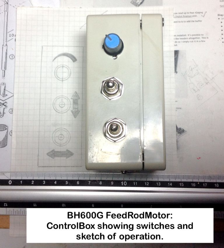
                                      Remote Control Station front showing controls and sketch of proposed decals:

                                      BH600G FeedRod Motor


                                      Geoff – Wonder if I will see the ISS at 1720h today.

                                      Edited By OuBallie on 24/12/2014 13:36:32

                                      #173511
                                      Les Jones 1
                                      Participant
                                        @lesjones1

                                        Hi Geoff,
                                        One suggestion. Make two keyhole slots in the back of the control box to match the existing threaded holes and make two shouldered screws to fit the existing holes.Also make a springy plate to go on the back of the box (Or fixed to the casting under the shouldered screws.) so the box had to be pressed against the casting to hook it on the keyhole slots. You could also counterbore the inside of the box at the top end of the slots so the box had to be pressed against the casting to remove it from the keyhole slots.

                                        Les.

                                        #173541
                                        Bazyle
                                        Participant
                                          @bazyle

                                          How about any one of the mounts used for bicycle lights – there have been various, or sort of relevant to ME a loco lamp. Or a dovetail like a QCTP (also used on the CVA fro dial indicator mounting)

                                          Have you built in an auto stop feature/trip?

                                          #174940
                                          OuBallie
                                          Participant
                                            @ouballie

                                            Les & Bazyle,

                                            Thanks for the suggestions.

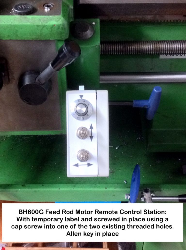
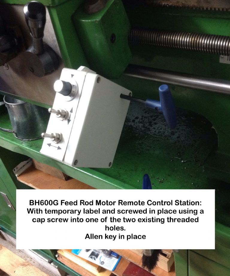
                                            Fitted the Threading Dial and that prevented the RH tapped hole from being used as it wouldn't allow the Remote Control Station (RCS) from being swivelled into a more useful position to operate the switches.

                                            I had already drilled one hole in the RCS some time ago, so just measured up and drilled a corresponding one in the cover in order to pass an Allen key through, and into the cap screw head.

                                            This works a treat, and can be tightened up so preventing the RCS from swivelling, now that only that one fastener is used.

                                            Used TouchDraw to do the label, emailed it to myself then printed it out at 30%.

                                            Just need to make a permanent label, with thanks to and as per 'mikesworkshop'.

                                            BH600G FeedRod Motor

                                            BH600G FeedRod Motor

                                            Geoff – This last bit took less time than is my norm.

                                          Viewing 20 posts - 1 through 20 (of 20 total)
                                          • Please log in to reply to this topic. Registering is free and easy using the links on the menu at the top of this page.

                                          Advert

                                          Latest Replies

                                          Home Forums Manual machine tools Topics

                                          Viewing 25 topics - 1 through 25 (of 25 total)
                                          Viewing 25 topics - 1 through 25 (of 25 total)

                                          View full reply list.

                                          Advert

                                          Newsletter Sign-up