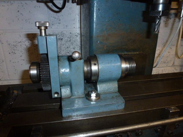
Using a gear to index a chuck

Advert

Using a gear to index a chuck

Home Forums General Questions Using a gear to index a chuck

Viewing 13 posts - 1 through 13 (of 13 total)
  • Author
    Posts
  • #494172
    Paul L
    Participant
      @paull58212

      Hi All,

      Many months ago I saw a drawing or photo of a setup that used a change gear and a plunger on a shaft to index a 3 jaw chuck,on the other end of said shaft by an amount of teeth (I may have imagined this!)

      I've tried the search function but to no avail. Can anyone point me in the right direction please?

      Paul

      Advert
      #27616
      Paul L
      Participant
        @paull58212
        #494174
        JasonB
        Moderator
          @jasonb

          As you have a Myford try this for starters

          #494177
          Paul L
          Participant
            @paull58212

            Thanks Jason.

            That is certainly the same principle but I'm thinking of a 'stand alone' version that I can use on a mill as a crude 4th axis.

            Maybe I saw that thread and and though I could adapt the idea for use on a mill, i really cant remember!

            Regards.

            #494209
            Peter G. Shaw
            Participant
              @peterg-shaw75338

              Could you be remembering my article in MEW293, May 2020 titled Dividing on the Warco 220? I used a changewheel fastened to an expanding bolt on the outer end of the lathe mandrel. Selection of the appropriate tooth or gap was by a spring loaded plunger.

              Although for the Warco 220, I can see no reason why it should not be adapted to any other lathe.

              Peter G. Shaw

              #494219
              Paul L
              Participant
                @paull58212
                Posted by Peter G. Shaw on 04/09/2020 15:28:23:

                Could you be remembering my article in MEW293, May 2020 titled Dividing on the Warco 220? I used a changewheel fastened to an expanding bolt on the outer end of the lathe mandrel. Selection of the appropriate tooth or gap was by a spring loaded plunger.

                Although for the Warco 220, I can see no reason why it should not be adapted to any other lathe.

                Peter G. Shaw

                Hi Peter,

                Unless article was shown somewhere else I didn't see it there as I didn't subscribe to MEW until about an hour ago!

                As soon as my login details arrive I will look back to that issue.

                Thank you for your assistance.

                Regards Paul

                #494243
                Martin Connelly
                Participant
                  @martinconnelly55370

                  Harold Hall has one on his website. Look at his metalworking index, dividing project.

                  Martin C

                  #494250
                  Martin Connelly
                  Participant
                    @martinconnelly55370

                    Joe Pie has an interesting video on the subject of dividing. Probably not suited to your current needs but worth a look.

                    Joe Pieczynski ​​​​indexing tips

                    Martin C

                    Edited By Martin Connelly on 04/09/2020 18:31:16

                    #494252
                    MichaelR
                    Participant
                      @michaelr

                      This may be what you are looking for Link

                      #494321
                      Clive Brown 1
                      Participant
                        @clivebrown1

                        p1020823.jpgCouple of photos to show my dividing arrangements made years ago.

                        One shows a detent plunger / change-wheel for my Boxford. The gear is on an expanding mandrel fixed in the lathe spindle bore. The spring loaded plunger mounts on the banjo, thus a wide range of change-wheel diameters can be accomodated. A 60 T is shown but I've used a 180 T to make protractor dials for a telescope mount.

                        The other picture shows a spin indexer I made when I first acquired my Raglan mill. The spindle is 3MT and has a Boxford nose. A 60 T change-wheel is mounted at the other end. The spindle can be locked. I can't remember where the casting came from, but it could also be fabricated. it may have been inspired by something in ME.

                        These items were made when commercial dividing equipment, rotary tables etc. was wellp1020819.jpg beyond the average model makers budget. Different now.

                        Edit; the lathe picture has somehow got flipped, but the idea's there.

                        Edited By Clive Brown 1 on 05/09/2020 11:32:30

                        #494326
                        Thomas Cooksley
                        Participant
                          @thomascooksley79020

                          Hi Paul, There is one in David Fenner's book:- THE MINI LATHE. It is for a Seig mini lathe but you may be able to adapt it. Tom.

                          #494331
                          Paul L
                          Participant
                            @paull58212

                            Clive, the one on the mill is exactly the application i had in mind. Thank you.

                            Thank you to everyone for the comments and suggestions.

                            When i bought me lathe it came with a 'box of bits', I think some of the components are from a dividing set but I'm not sure. Any one recognise these parts?


                            qwe.jpg

                            Edited By Paul Liddle on 05/09/2020 12:12:42

                            Edited By Paul Liddle on 05/09/2020 12:14:05

                            Edited By Paul Liddle on 05/09/2020 12:14:47

                            Edited By Paul Liddle on 05/09/2020 12:17:17

                            Edited By Paul Liddle on 05/09/2020 12:17:32

                            Edited By Paul Liddle on 05/09/2020 12:20:06

                            #494352
                            Bazyle
                            Participant
                              @bazyle

                              The only non-obvious dividing head part is top left which is a tailstock support for possibly a Myford dividing attachment. Measure the bar, report here and someone can check against theirs.
                              Bottom left is probably meant to be mounted in a chuck or the tailstock (note keyway which might match the key for the tailstock barrel). At the headstock end it would work as an 'eccentric chuck' as used by ornamental turners and for drilling off centre, and at the tailstock end again for drilling but rather limited use.
                              Centre might be a chuck holder for the tailstock and the thick disc also a chuck mount.
                              Far right looks like it might go throgh the main spindle to hold a slitting saw, or be an adjustable backstop behind the chuck, or hold the index disc behind the spindle.
                              Also look at everything for something with 3 holes that match your index plate or the offset single hole it has.

                              edit : just noticed the middle bar thing to the left of the index plate may have a matching hole.

                              Edited By Bazyle on 05/09/2020 17:40:01

                            Viewing 13 posts - 1 through 13 (of 13 total)
                            • Please log in to reply to this topic. Registering is free and easy using the links on the menu at the top of this page.

                            Advert

                            Latest Replies

                            Home Forums General Questions Topics

                            Viewing 25 topics - 1 through 25 (of 25 total)
                            Viewing 25 topics - 1 through 25 (of 25 total)

                            View full reply list.

                            Advert

                            Newsletter Sign-up