Stopping Unwanted Ribbons of Swarf?

Advert

Stopping Unwanted Ribbons of Swarf?

Home Forums Beginners questions Stopping Unwanted Ribbons of Swarf?

Viewing 25 posts - 1 through 25 (of 31 total)
  • Author
    Posts
  • #8733
    SillyOldDuffer
    Moderator
      @sillyoldduffer
      Advert
      #299848
      SillyOldDuffer
      Moderator
        @sillyoldduffer

        Turning aluminium or steel my lathe produces long ribbons of swarf most of the time, up to 5m long! It does this with HSS and Carbide despite both tools having chip-breaker edges.

        The ribbons get tangled around the tool-post and have to be cleared regularly. They get caught between the tool and the work and spoil the finish. When I had a mini-lathe a ribbon found it's way into the electrics and started a firework display. Blood has been drawn by a ball of swarf flung in my face when it caught in the chuck, and the steel ribbon can be razor sharp and smoking hot. I do not like ribbons.

        Once in a while the lathe breaks the ribbon at each turn or so. This is exactly what I want, but I don't know what I'm doing different to cause chips to form.

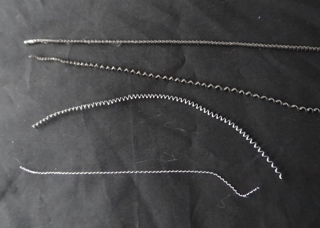
        I have a book that says the cure is to increase the depth of cut. Trying this just produces heavier ribbons:

        dsc04428.jpg

        The top example is from 1" diameter mild-steel cut 0.6mm (24 thou) deep (ie 1.2mm off the diameter) at 2000rpm with a carbide insert. Though the lathe doesn't seem to mind I think this is a heavy cut. The example underneath is the same rod cut 0.2mm deep.

        The two lower examples are 20mm diameter Aluminum Alloy cut with HSS at 500 rpm. The lower example is a 0.1mm deep cut, the upper 0.2mm (8 thou).

        The lathe is a Warco WM280 with a 1500W 3-phase motor and VDF.

        What's the best way of producing chips rather than ribbons please?

        Dave

        #299849
        Tony Pratt 1
        Participant
          @tonypratt1

          I thought increasing the feed rate cured this problem not increasing the depth of cut?

          Tony

          #299853
          MW
          Participant
            @mw27036

            Try T6 aluminium, it's designed to chip rather than string, which is what 6606 tends to do. The finish is wonderful too.

            Another method might be to think about the design of your tools, some top rake might reduce this tendency. 

            Intermittent feed (or dithering as I call it) might also help as this breaks the continuity of the string on continuous or automatic feed. Tends to be a good technique for roughing.  

            Michael W


            Edited By Michael-w on 27/05/2017 18:30:36

            #299855
            Anonymous

              First thing is to bin the book.

              Second thing is to repeat this mantra – feedrate, feedrate, feedrate

              For 1" diameter steel I'd be running at 1200rpm. The DOC ideally needs to be more than the nose radius of of the insert, although that it does depend upon the material. For roughing I use 0.1" (0.2" off the diameter) which is convenient as it is one turn of the cross slide handle. Finishing cuts may be 20-40 thou depending upon how much material is left.

              To get the insert chip breakers to work you need higher feedrates. For steel 4 thou per rev is about the minimum I use, but often 6 thou per rev for roughing. Aluminium seems to need higher feedrates, say 8-10 thou per rev, even with inserts designed for aluminium.

              If you buy inserts in quantity they come in boxes with cutting details on the back. Here are some typical figures:

              Korloy CCMT09T304 NC3220 for steel: DOC 0.30 to 3.00mm feedrate 0.08 to 0.23mm surface speed 150 to 350m/min

              Korloy CCGT09T304 H01 for aluminium: DOC 0.10 to 5.00mm feedrate 0.02 to 0.30mm surface speed 100 to 200m/min

              It's interesting that the minimum recommended DOC, feedrate and surface speeds are less for aluminium than for steel.

              Andrew

              #299858
              SillyOldDuffer
              Moderator
                @sillyoldduffer
                Posted by Andrew Johnston on 27/05/2017 18:42:00:

                First thing is to bin the book.

                Second thing is to repeat this mantra – feedrate, feedrate, feedrate


                Andrew

                I'd got into the habit of leaving the lathe set at the lowest feed-rate with the notion that this produced the best finish. Well maybe for the finishing cuts, but I hadn't thought it through.

                After chanting the manta I just tried the lathe at 1200rpm with 4x the feed-rate. The tendency to ribbon is much reduced, it cuts well and – bonus – it removes metal much faster.

                There's an odd bit of stainless scrap piping in the chuck at the moment so I shall be trying again tomorrow with a known mild steel. I'm pretty confident in the result though. I shall look into the insert too – it came with the holder and although it cuts it may not be ideal.

                Yet again I'm feeling dim – I must have tried changing everything on the lathe apart from the feed-rate. I've also twigged that there was less ribbon produced when I cranked the saddle by hand rather than using self-act. If only I'd joined the dots…

                Many thanks,

                Dave


                Edited By SillyOldDuffer on 27/05/2017 19:34:27

                #299876
                John Reese
                Participant
                  @johnreese12848

                  The advice given was all good.. I would like to add an observation. Carbide inserts are designed for industrial use. Most hobby lathes do not have the rigidity or the horsepower to achieve the recommended speeds, feedrate, and depth of cut recommended by the manufacturers of the inserts. With our lighter equipment we cannot necessarily expect them to perform as advertised.

                  #299882
                  Muzzer
                  Participant
                    @muzzer

                    This brings to mind the tests I did some time ago, provoked by some photos of gratuitous swarf in the South Bend book. It seems that in those days, a machinist had to aim for giant swarf if he wanted to consider himself a real man in the lathe department.

                    As Andrew says, cranking the feedrate (and surface speed) up is usually the solution when using inserts. The chipbreakers don't tend to work otherwise.

                    Murray

                    #299884
                    Neil Lickfold
                    Participant
                      @neillickfold44316

                      You need finishing inserts as the cut depth for hobby lathes and total HP is not enough to properly run the standard turning inserts and no where near the required power for roughing inserts. In finishing inserts they have chip breaker designs that make very small cuts curl and chip. Most finishing inserts are maxed out at a 1mm depth of cut, some are less than that. My current favourite insert are these little beauties, from Kyocera, CCGT060202MP-CK PR1425 I have a turning tools holder and a couple of different sized boring bars. Don't be fooled by the small size of these inserts. I get the 0.2mm radius and does most things. These are capable of turning bearing steel to aluminium. I also have the TNMG16 inserts, these are TNGG160402R-S PR1125 and the TNGG160404R-S PR1125 These are the 0.2 and 0.4 mm nose radius. I only have these in Right hand as I do not have a boring bar holder for the TNMG inserts. These PR1125 coated inserts cut bearing steels just fine as well. I also have DCMT11T3 turning holders and use the H1 aluminium finishing inserts for all metals except on Bearing steels. Most of my turning is all done by hand feed, I seldom use power feed.

                      Neil

                      #299908
                      Anonymous
                        Posted by SillyOldDuffer on 27/05/2017 19:33:38:

                        I shall look into the insert too – it came with the holder and although it cuts it may not be ideal.

                        Depends on the brand. My limited experience of cheaper toolholders (Glanze) is that the toolholders are fine, but the supplied inserts were poor.

                        The problem with dots is that not only is it not always obvious how to join them up often I don't even see the dots. sad

                        Andrew

                        #299915
                        Clive Hartland
                        Participant
                          @clivehartland94829

                          A chip breaker incorporated in the tool tip fixes the problem!

                          #299929
                          SillyOldDuffer
                          Moderator
                            @sillyoldduffer

                            I've been playing about this morning and came across another factor.

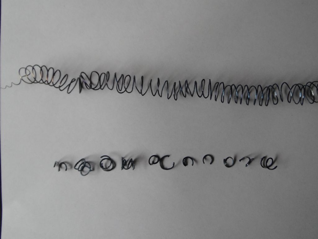
                            The photo is, I think, 'quite interesting' in that it shows that the state of the carbide insert matters as well as the feed-rate.

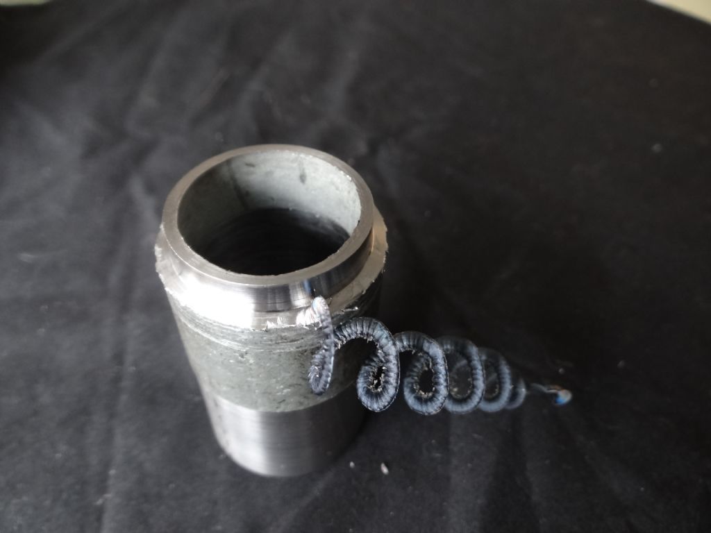
                            The test piece is an unknown variety of stainless steel pipe. It doesn't seem to work harden. The top coil of swarf was produced at medium feed-rate with the well-used tip of a triangular insert used mostly on steel. The broken up sample underneath resulted from exactly the same settings (Cut 0.3mm deep at 1200 rpm) except that the insert was rotated in the holder to present a fresh tip.

                            dsc04430.jpg

                            It appears that a blunt tip is more likely to produce ribbons than a sharp one. But how do you tell when a tip used on a variety of metals by an amateur is worn? It's not obvious by eye-balling it.

                            Thanks also for advice posted since Andrew's first response. It's all been noted!

                            Dave

                            #299939
                            Tony Pratt 1
                            Participant
                              @tonypratt1

                              Not being funny but if a tip is worn/blunt you will be able to see some physical difference compared to a new tip. There may also be a build up of metal on the tip itself which could affect performance

                              Tony

                              #299944
                              Clive Foster
                              Participant
                                @clivefoster55965

                                The great thing about quality name brand inserts is that they generally do exactly what it says on the box when used as specified on appropriate materials. It, as in Daves pictures, the chip-breaker isn't doing its job then the insert is worn and should be replaced. Somewhat counterintuitively its actually the chip breaker part that wears out first when used as specified. The Sandvik book, modern metal cutting, has nice pictures and some details. The sharp edge merely serves to get under the skin of the material at the start of the cut. When cutting the crack should be a bit in front of the actual tip so the chip flows down the tool into the chip breaker groove where it snaps off due to a combination of mechanical stress as it curls round and thermal stress due to uneven cooling. If the edge is insufficiently sharp or machine insufficiently rigid the initial penetration doesn't work properly so the insert doesn't function as designed so rarely works properly. The actual edge geometry is a bit delicate under certain circumstances being easily deranged by rubbing contact. Which always seems odd given that the edges are plenty strong enough to stand up to running straight into fast moving stock at a considerable rate of feed. More than one type of strength.

                                Time was model engineers use of carbide was in brazed tip tooling form for dealing with difficult and abrasive materials so techniques loosely derived from HSS worked well enough. The modern insert is a heavily designed metal removal device and generally needs to be used as per book for good results. We can't afford to have the right one for every job so decent lists of the ones that will work over a wide range of materials and off book conditions are desirable.

                                Important to read the label before purchase too. I picked up some Sandvik ones that give an awesome finish at book speeds but misread surface speed. Thought I was getting inserts for 425 ft/min, fast but do-able. Actual is 425 m/min, seriously scary!

                                Clive.

                                #299947
                                Hopper
                                Participant
                                  @hopper

                                  24 thou is not a deep cut. Try more like 100 thou for roughing cuts. Plus up the feed rate. Plus try varying the angle of approach the tool is set at, ie cutting edge set square to the lathe axis will tend to chip more than if the edge is set at an angle. Also try setting the tool slightly below centre height. And vary the RPM. Any of these factors can influence swarf shape, with no real hard and fast rules that this one does that etc. More of a combination of factors.

                                  It can also be a factor of the material you are using. Ordinary mild steel will tend to chip up more than some of the alloy steels, which do tend to make long strings more. Same with aluminium. Different grades machine differently.

                                  #299953
                                  SillyOldDuffer
                                  Moderator
                                    @sillyoldduffer
                                    Posted by Tony Pratt 1 on 28/05/2017 11:44:06:

                                    Not being funny but if a tip is worn/blunt you will be able to see some physical difference compared to a new tip. There may also be a build up of metal on the tip itself which could affect performance

                                    Tony

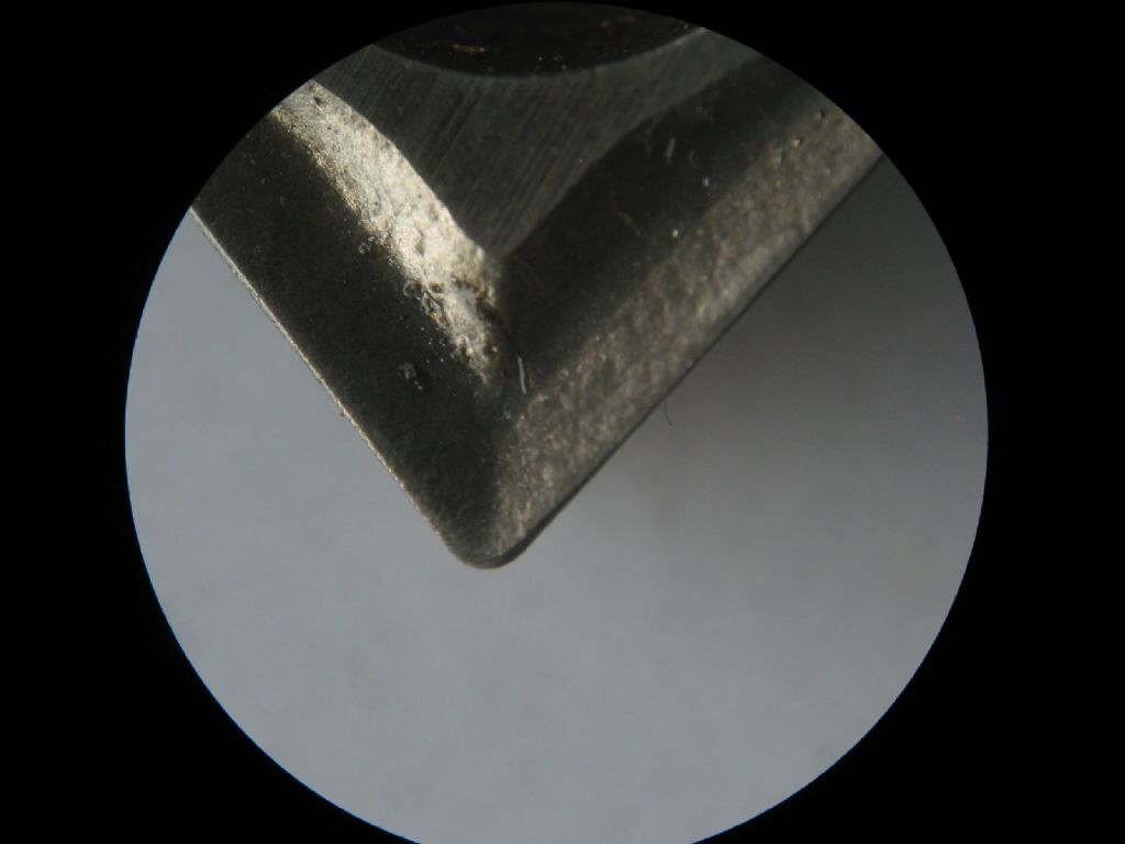
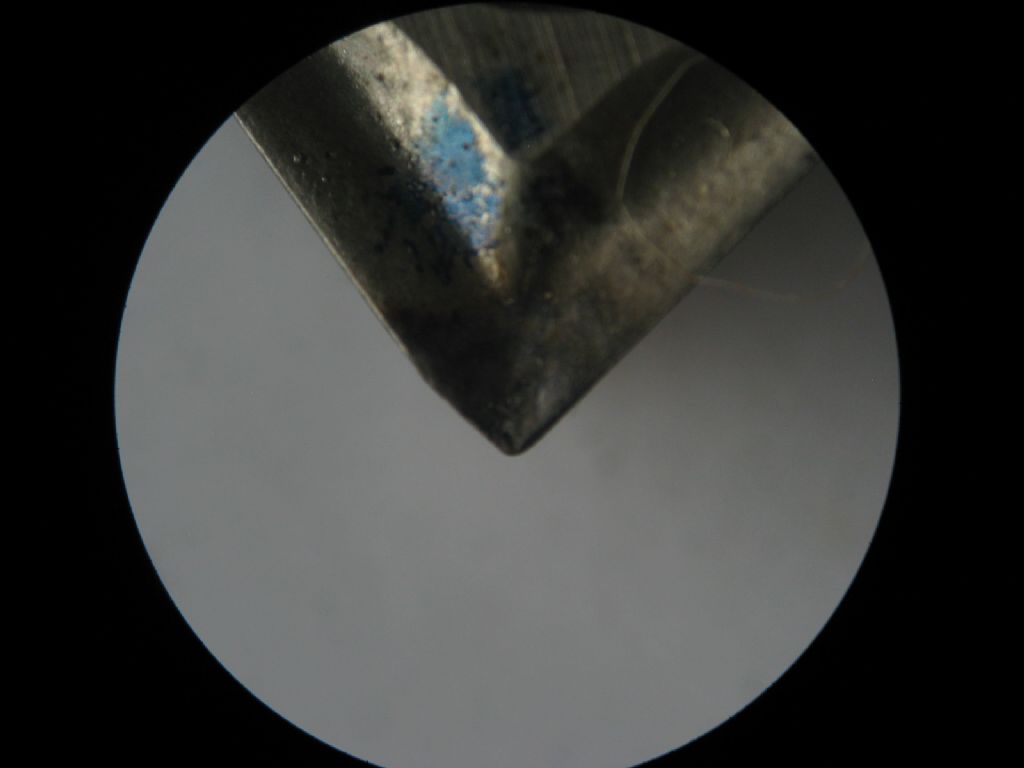
                                    Yes, it may be my eye-sight. With a loupe I can see damage, and it's even more obvious with a low power microscope.

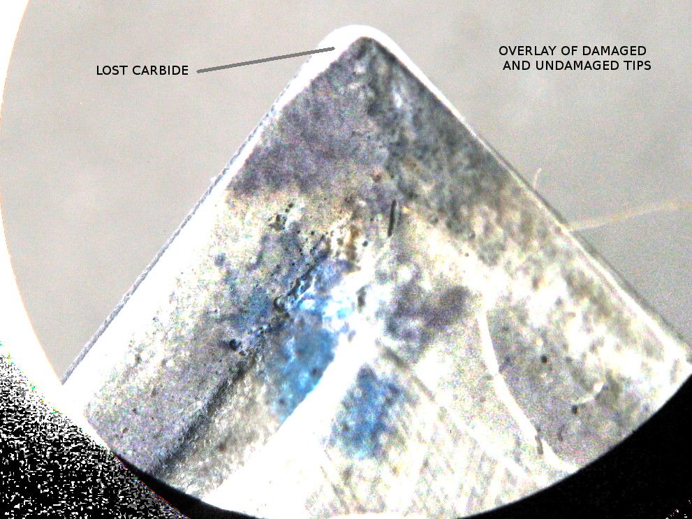
                                    First undamaged tip with a neat radius:

                                    img_3864.jpg

                                    Second, damaged tip, much more pointy:

                                    img_3865.jpg

                                    Third, an overlay of the two tips digitally tweaked to highlight the difference:

                                    overlay.jpg

                                    Not sure how I did the damage – might have been me rather than fair wear and tear. Clive mentions rubbing and I did tweak the tool-height to discourage that fairly recently. Or possibly it was rubbing because of the damage. Dunno.

                                    Dave

                                    #299969
                                    Clive Foster
                                    Participant
                                      @clivefoster55965

                                      If memory serves me right that seems pretty similar to some of the pictures in my copy of the Sandvik publication "Modern Metal Cutting.". Unfortunately its not the easiest of books to dip into and out of. probably because it was produced as a reference work accompanying an online course. Presumably if you took the course you'd understand where to find what.

                                      Maybe the downloads here :- **LINK** would be useful. Training Guide and Turning Handbook look promising.

                                      A fast skim through the first few pages of the Training Guide pulls up some nice pictures of the speeds and feeds pertaining to the acceptable chip breaking region for, presumably, typical inserts.

                                      Years worth of bedtime reading methinks!

                                      Clive.

                                      #299979
                                      Muzzer
                                      Participant
                                        @muzzer

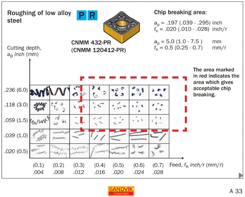
                                        Yes, interesting to browse through this kind of material Clive. One section that stands out is the pages around page A33 including this "chip breaking area" illustration. You probably need to get the surface speed right too but this is interesting on its own:

                                        chipbreaking area.jpg

                                        Clearly the actual numbers will be dependent on the type of insert geometry, not least positive or negative insert rake angle. The final rake angle is also a function of the particular geometry at the cutting edge itself which can vary even within a particular family of insert styles.

                                        Murray


                                        Edited By Muzzer on 28/05/2017 15:28:35

                                        #299980
                                        SillyOldDuffer
                                        Moderator
                                          @sillyoldduffer
                                          Posted by Hopper on 28/05/2017 12:15:02:

                                          24 thou is not a deep cut. Try more like 100 thou for roughing cuts.


                                          I don't really want to break my toy lathe but you dared me!

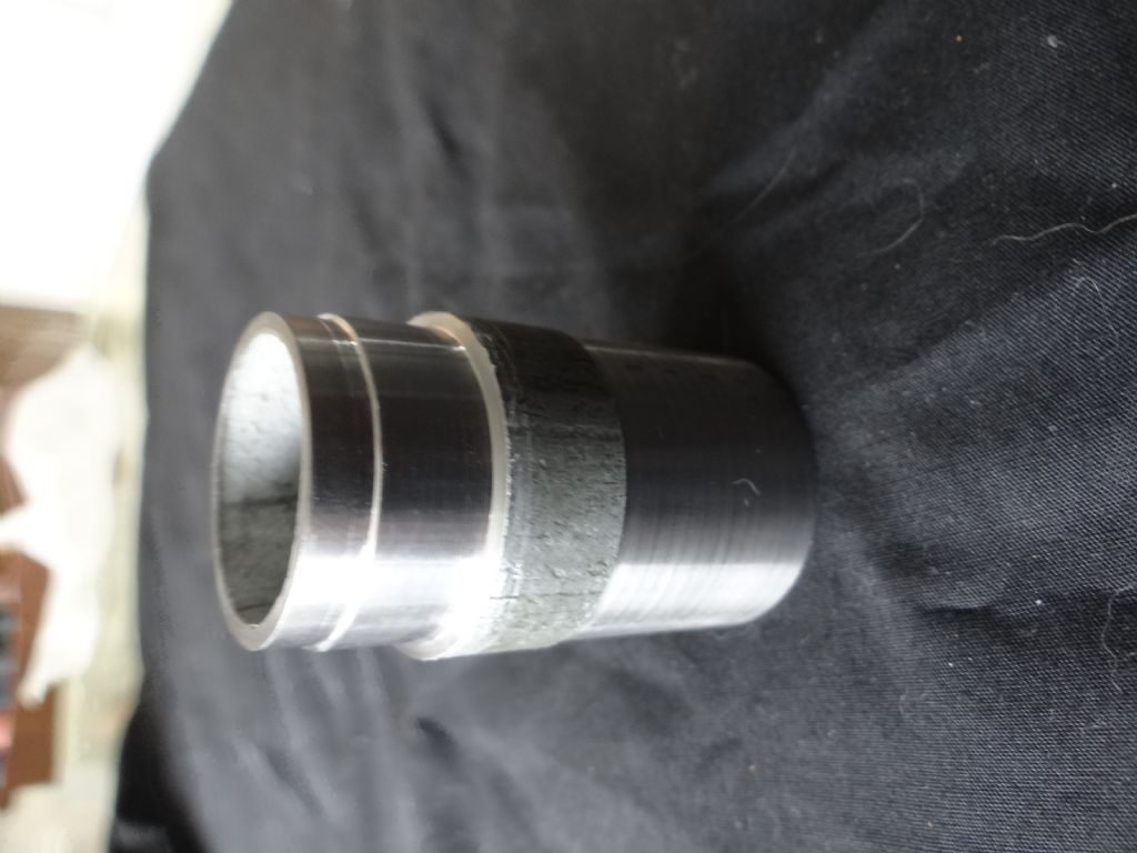
                                          At 1200 rpm it will take a 2mm deep cut (about 80 thou) provided I move the saddle manually. With self-act (at 0.14mm per revolution) I got a ribbon followed by a jam. No damage done to the lathe.

                                          dsc04431.jpg

                                          The lathe has no trouble taking a 1.5mm (60 thou) deep cut. Not sure I'm happy about it though, the chips come off like shrapnel.

                                          dsc04432.jpg

                                          The decent finish I'm getting from thrashing the insert makes me wonder what would happen if I doubled the rpm. Perhaps the irresistible desire to push the lathe even harder is a warning that I'm mucking about and heading for trouble. To calm me down I'll be looking at Clive's link next. A bit of theory should be safe enough.

                                          Dave


                                          Edited By SillyOldDuffer on 28/05/2017 15:29:21

                                          #299992
                                          MW
                                          Participant
                                            @mw27036

                                            I have been known to rough steel with HSS taking 4mm deep cuts blushI'm not impatient, honest!

                                            Michael W

                                            #300022
                                            Muzzer
                                            Participant
                                              @muzzer

                                              The Sandvik manual has a rule of thumb "the depth of cut should be no less than 2/3 of the nose radius". That seems to make sense.

                                              Personally, for roughing I try to turn the speed up to somewhere near the peak power rating of the motor / VFD, to get the inserts working in a region approaching the recommendations. The surface finish tends to be improved as well as the swarf and material removal rate.

                                              Murray

                                              #300030
                                              SillyOldDuffer
                                              Moderator
                                                @sillyoldduffer

                                                Assuming the lathe is strong enough the main limit to depth of cut is the power available. This online calculator has values for various materials listed and is easy to use.

                                                My lathe only has a 1500W motor. Using the calculator, I worked out that the maximum DOC I should attempt in steel with 1200 rpm feeding at 0.14mm per revolution is about 1.4mm. This is the bottom left-hand corner of Muzzer's red box on the Sandvik table. It explains why I've been cutting ribbons: my WM280 is only just powerful enough to cut properly with carbide and I don't normally push it that hard. To fully exploit carbide the online calculator suggests rather more oomph than I have, 6000W would do!

                                                Although I'm very happy with my WM280, I'm not sure how long it would last if I spent all day taking 1.4mm cuts with it!

                                                Dave

                                                #300053
                                                duncan webster 1
                                                Participant
                                                  @duncanwebster1

                                                  I used to take 1mm cuts at 0.1mm per rev on an ML7, but using HSS, so slower spindle speed. With most amateur's lathes I don't see the need for carbide, and HSS is a lot cheaper. Tool grinding is not as difficult as some people seem to think, and those tangential tool holders from Eccentric Engineering are wonderful

                                                  Edited By duncan webster on 28/05/2017 23:28:36

                                                  #300085
                                                  Anonymous
                                                    Posted by SillyOldDuffer on 28/05/2017 21:24:06:

                                                    My lathe only has a 1500W motor. Using the calculator, I worked out that the maximum DOC I should attempt in steel with 1200 rpm feeding at 0.14mm per revolution is about 1.4mm.

                                                    Using these figures, and assuming a bar diameter of 1" I get a removal rate of about 1.15in³ per minute. A rule of thumb is that 1hp will remove 1in³ per minute in low carbon steel. Experiment has shown that my lathe starts to struggle at a removal rate of about 2.8in³ per minute. That makes sense as it has a 3hp motor, allowing for some loss in the belt drive and geared headstock.

                                                    So it seems possible that the 1500W motor is not producing 1500W at the spindle. GIven it's driven by a VFD I'd sugest it is runnig below base speed?

                                                    Andrew

                                                    #300090
                                                    Hopper
                                                    Participant
                                                      @hopper
                                                      Posted by SillyOldDuffer on 28/05/2017 15:28:58:

                                                      Posted by Hopper on 28/05/2017 12:15:02:

                                                      24 thou is not a deep cut. Try more like 100 thou for roughing cuts.

                                                      I don't really want to break my toy lathe but you dared me!

                                                      At 1200 rpm it will take a 2mm deep cut (about 80 thou) provided I move the saddle manually. With self-act (at 0.14mm per revolution) I got a ribbon followed by a jam. No damage done to the lathe.

                                                      dsc04431.jpg

                                                      The lathe has no trouble taking a 1.5mm (60 thou) deep cut. Not sure I'm happy about it though, the chips come off like shrapnel.

                                                      dsc04432.jpg

                                                      The decent finish I'm getting from thrashing the insert makes me wonder what would happen if I doubled the rpm. Perhaps the irresistible desire to push the lathe even harder is a warning that I'm mucking about and heading for trouble. To calm me down I'll be looking at Clive's link next. A bit of theory should be safe enough.

                                                      Dave

                                                      Edited By SillyOldDuffer on 28/05/2017 15:29:21

                                                      What is that material you are turning in the pics? If ally, you might need to use the CCGT ground inserts to cut it a bit cleaner. Or HSS. You should be able to take massive cuts in ally if you have a nice sharp tool bit. If it is steel, is it some kind of galvo pipe? Probably never get it to machine nicely. Pipe making does weird stuff to steel and it never ends well for doing much other than conveying liquids.

                                                    Viewing 25 posts - 1 through 25 (of 31 total)
                                                    • Please log in to reply to this topic. Registering is free and easy using the links on the menu at the top of this page.

                                                    Advert

                                                    Latest Replies

                                                    Home Forums Beginners questions Topics

                                                    Viewing 25 topics - 1 through 25 (of 25 total)
                                                    Viewing 25 topics - 1 through 25 (of 25 total)

                                                    View full reply list.

                                                    Advert

                                                    Newsletter Sign-up