Restoring Beaver VBRP Mill

Advert

Restoring Beaver VBRP Mill

Home Forums Manual machine tools Restoring Beaver VBRP Mill

Viewing 25 posts - 126 through 150 (of 182 total)
  • Author
    Posts
  • #266467
    Alan Waddington 2
    Participant
      @alanwaddington2

      Rob

      as discussed there are other alternatives, even if the single VFD is not really viable.

      So if the machine fits your needs, buy it, and worry about powering it up once it's sat in your workshop.

      A lad on another forum I visit has just bought a 15hp Haas CNC to go in his garage, and is now researching power options…….now there's a proper challenge

      Al

      Advert
      #266516
      Robonthemoor
      Participant
        @robonthemoor
        Posted by Daniel Robinson on 13/11/2016 18:11:24:

        I will load the tutorial and take a couple of pic's that is the wiring for my garage tomorrow. always interested to hear another view but if its working and and someone tells you otherwise you have to question… Why?

        Dan

        I like your train of thought, I will look forward to the pics, just got an email from the eBay beaver mill owner, he's given me 30 minutes to look round it & check it with gauges, can't look at that in 30 mins he's also a bit rude.

        #267233
        Alan Waddington 2
        Participant
          @alanwaddington2

          Did you buy it Rob ?, still being advertised, but with a slight price increase surprise

          image.jpg

          #267243
          Robonthemoor
          Participant
            @robonthemoor
            Posted by Alan Waddington 2 on 18/11/2016 22:31:51:

            Did you buy it Rob ?, still being advertised, but with a slight price increase surprise

            image.jpg

            #267244
            Robonthemoor
            Participant
              @robonthemoor

              No the mans a dick head

              Edited By Robonthemoor on 19/11/2016 05:02:37

              #267261
              Ajohnw
              Participant
                @ajohnw51620

                I more than suspect that the problem with having contactors on the output of a VFD is inductance and other problems. Open them and spikes may blow the unit also the problem of making all 3 break at the same time.

                However if one motor is always running – the biggest and that doesn't have a contactor there will be some where for the spikes to go and no uneven breaker opening problems or a situation where the inverter is suddenly driving nothing at all.

                It is a curious area though as it's the motor that usually provides the inductance that is driven switch mode style to vary the frequency but comments about manuals saying don't fit anything between the inverter and motor are correct. Sort of suggest that there is a clean shut down problem – the inverter will continue to try and switch mode the motor when it's not connected.

                The transwave phase converters use exceedingly expensive capacitors and other bits and pieces which part explains the price. There is a switch on them used to tune them to the motor power they are connected to. That may cause problems if significant powers are switched in and out.

                I would simply use contactors or hefty relays on the auxiliary motors and make them them self latching via push buttons so that they disconnect when the power goes also ideally when the main motor is turned off. I once saw the top castings of a huge milling machine break because some one left the table lift power feed on.

                Self latching is easy on relays. A push button is used to pull them in and one of the normally open contacts used to hold it in. That feed can then have another push button to break that circuit to cause it to drop out. This can be done using 240 mains relays but personally I would use a simple 12v dc supply. I once tried to do the same sort of thing with thyristors at work. Not being able to snub the circuit adequately caused all sorts of problems. Changed them to 2 bipolar transistors connected to emulate a thyristor and all was ok and lots of them worked reliably for years. Low current stuff though. Done because relay contacts can passivated if currents are very low and gold flashed contacts don't always help.

                John

                #267386
                Robonthemoor
                Participant
                  @robonthemoor
                  Posted by Alan Waddington 2 on 18/11/2016 22:31:51:

                  Did you buy it Rob ?, still being advertised, but with a slight price increase

                  The man is a complet disaster, he just waisted mine "" & all the good people like yourself time, what a nasty man. I bet he's great to work for😡😲

                  #267387
                  Robonthemoor
                  Participant
                    @robonthemoor
                    thankfor that I Posted by Ajohnw on 19/11/2016 10:07:55:

                    I more than suspect that the problem with having contactors on the output of a VFD is inductance and other problems. Open them and spikes may blow the unit also the problem of making all 3 break at the same time.

                    However if one motor is always running – the biggest and that doesn't have a contactor there will be some where for the spikes to go and no uneven breaker opening problems or a situation where the inverter is suddenly driving nothing at all.

                    It is a curious area though as it's the motor that usually provides the inductance that is driven switch mode style to vary the frequency but comments about manuals saying don't fit anything between the inverter and motor are correct. Sort of suggest that there is a clean shut down problem – the inverter will continue to try and switch mode the motor when it's not connected.

                    The transwave phase converters use exceedingly expensive capacitors and other bits and pieces which part explains the price. There is a switch on them used to tune them to the motor power they are connected to. That may cause problems if significant powers are switched in and out.

                    I would simply use contactors or hefty relays on the auxiliary motors and make them them self latching via push buttons so that they disconnect when the power goes also ideally when the main motor is turned off. I once saw the top castings of a huge milling machine break because some one left the table lift power feed on.

                    Self latching is easy on relays. A push button is used to pull them in and one of the normally open contacts used to hold it in. That feed can then have another push button to break that circuit to cause it to drop out. This can be done using 240 mains relays but personally I would use a simple 12v dc supply. I once tried to do the same sort of thing with thyristors at work. Not being able to snub the circuit adequately caused all sorts of problems. Changed them to 2 bipolar transistors connected to emulate a thyristor and all was ok and lots of them worked reliably for years. Low current stuff though. Done because relay contacts can passivated if currents are very low and gold flashed contacts don't always help.

                    John

                    -thanks for your input John nice little read that.👍

                    #267416
                    Alan Waddington 2
                    Participant
                      @alanwaddington2
                      Posted by Robonthemoor on 19/11/2016 19:05:37

                      The man is a complet disaster, he just waisted mine "" & all the good people like yourself time, what a nasty man. I bet he's great to work for😡😲

                      That's a shame, plenty more fish in the sea though Rob……..large turrets are not exactly thin on the ground.

                      #268278
                      Alan Waddington 2
                      Participant
                        @alanwaddington2

                        Have you seen this Rob ?

                        **LINK**

                        Edited By Alan Waddington 2 on 24/11/2016 20:38:08

                        #268290
                        Robonthemoor
                        Participant
                          @robonthemoor

                          Beaver Looks good, I'm going to look at a gate milling machine tomorrow Friday, I can't find anything about them,, why"" can any one point me in the right direction for some info, tony@lathes as no listing for them, help😐

                          #268449
                          Phil Whitley
                          Participant
                            @philwhitley94135
                            #268450
                            Phil Whitley
                            Participant
                              @philwhitley94135
                              #273522
                              Robert James 3
                              Participant
                                @robertjames3

                                Guys please pardon the interuption. I am across the pond in the States I have a Beaver Mill that I just powered up today for the first time. What a thrill since I had to use a phase convertor. Can someone point me to a forum for these machines. Many thanks in advance. I am suscribed to this thread so I should see any post.

                                #273550
                                Alan Waddington 2
                                Participant
                                  @alanwaddington2

                                  Hi Robert

                                  Welcome to the Beaver thread, good to hear you have yours up and running.

                                  I'm not aware of any forums dedicated specifically to Balding machinery, I guess as a minority manufacturer they don't generate the interest of more mainstream makes such as Bridgeport.

                                  There are a couple of Beaver rebuild threads knocking about on the web including this one, and manuals are freely available.

                                  Can you post some pics of your Stateside Beaver ? I wonder if there were any differences on the exported machines.

                                  Regards

                                  Alan.

                                  #273654
                                  Robonthemoor
                                  Participant
                                    @robonthemoor

                                    ​This is the gate G 301D 3hp int or bt40 taper. How do I get that brake unit off the head, it has 4 Allen keys & just looks like it should just lift off but seems to be a little reluctant. You can see the brake lever at the top of the head, & the square bit that needs removing.

                                    #273781
                                    Robert James 3
                                    Participant
                                      @robertjames3

                                      Hi Alan,

                                      I am finding this forum very hard to use so pardon me it my posts are not right. Here is a Icloud album with pictures of my Beaver Mill and my South Bend Lathe. In the photo that shows the main switch you'll see the switch hanging out of the box. Do you know anything about these switches? I don't and don't know how to check one out. Any advice would be greatly appreciated.

                                      **LINK**

                                      Thanks, Bob

                                      #273810
                                      Alan Waddington 2
                                      Participant
                                        @alanwaddington2

                                        Hi Robert

                                        Interesting photographs……Your machine looks to be in good condition, certainly the paint is more intact than mine ( assuming its original) There seems to be lots of variation between VPRB's, i don't know if this is down to development and product evolution over the lifespan of the model or if there was a basic model with an 'options' list. My serial number is 10,309/2 so I'm guessing quite a bit later than yours which seems to be 4769/2

                                        For example there are lots of pictures showing VPRB's with a slotting head on the back of the overarm, the overarm has a large lug cast at the back to bolt the head to. Mine however is like yours, the lug is not present, just a flat face with a hole in it.

                                        I also noted that your overarm is fixed centrally, the one on mine has dovetail slides, and can be moved back and forth. Also you don't seem to have power feed to X, which most including mine have, although I've seen at least two different types of feed gearbox fitted. Some also have power to Y & Z

                                        Difficult to tell from the pictures, but i would hazard a guess that the rotary switch hanging down is simply a 3 phase isolater (It is on mine located in the same position)

                                        Am hoping to get some time in the workshop this week, have a new VFD to wire up to the mill.

                                        #273844
                                        Robert James 3
                                        Participant
                                          @robertjames3

                                          Alan what is a 3 phase isolater? In the one picture from the back (you may have to move down on the picture) I have a Rotary Phase Convertor sitting on a piece of plywood temporarily till I can find some Isolators.

                                          #273850
                                          Alan Waddington 2
                                          Participant
                                            @alanwaddington2
                                            Posted by Robert James 3 on 27/12/2016 00:24:05:

                                            Alan what is a 3 phase isolater? In the one picture from the back (you may have to move down on the picture) I have a Rotary Phase Convertor sitting on a piece of plywood temporarily till I can find some Isolators.

                                            A 3 phase isolator is just a switch that disconnects the machine from the incoming mains supply, looking at your photos, you have hooked up the rotary converter direct to the main motor of the mill ?

                                            this will bypass all the existing wiring contactors and switches etc.

                                            if you look inside the panel at the back I suspect you will find the connections where the original 3 phase supply would have been connected. If you wire your RPC up to them, all the switches on the mill should work as originally intended including the isolator hanging down.

                                            #273852
                                            Robonthemoor
                                            Participant
                                              @robonthemoor

                                              Don't assume from a transwave when you wire it up everything will work as it should!! Not so in some cases, my transwave will not power the motor properly on my mill through all the relays in the back, but it does power the coolant pump & the x drive motor ok. If the transwave is at its max ☹️ The motor can be noisy in one direction. Transwaves are not true phases! Wire your vfd straight to the motor then use the transwave for lower hp motor through the correct way of conecting the mill to 3 phase 415v

                                              #274532
                                              Alan Waddington 2
                                              Participant
                                                @alanwaddington2

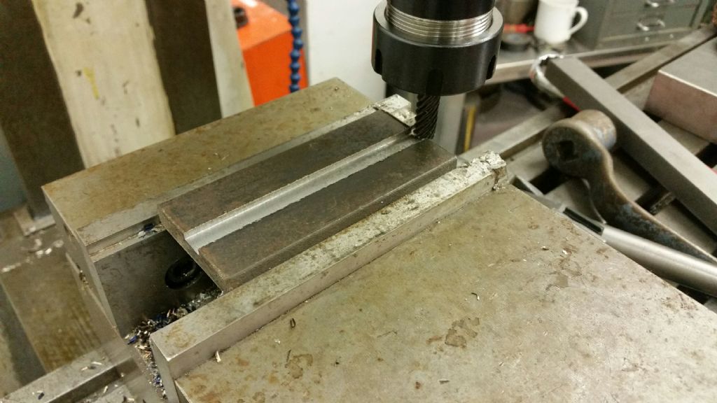
                                                Had some time in the workshop over the last few days, wired the head up to a new VFD inverter, put the table feed gearbox back together and fitted the motor to it (these items all came loose in a box with the mill), wired the feed motor to my RPC for the time being, eventual plan is to buy a smaller inverter to run the feed motor. Filled the head and gearbox with oil…………

                                                All seems to work as it should, so bolted on a machine vice and took a test cut…….yay it works 20161230_182452_resized.jpg

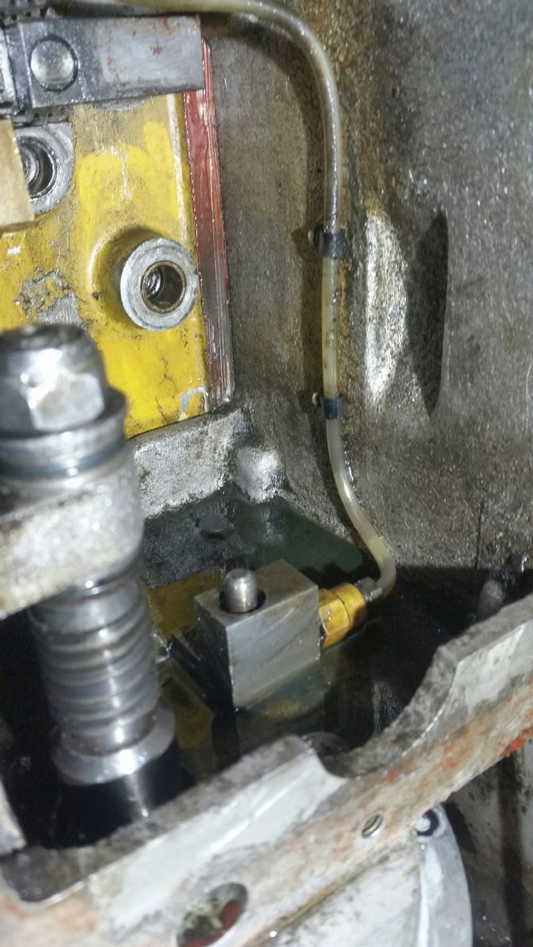
                                                One thing i can't figure out is the machine is piped for way lubrication, I found a pump in the bottom of the table feed gearbox, which runs from a cam on the bottom gear shaft. What i can't get my head round, is how the oil would be topped up…….or does it use the oil from the gearbox and pump that out on a total loss basis, presumably you would then keep topping up the gearbox ? If so then it would need really thin oil in the gearbox like hydraulic fluid ?

                                                20161228_181014_resized.jpg

                                                #274710
                                                Mark Rand
                                                Participant
                                                  @markrand96270

                                                  That pump is for the table feed gearbox itself. On the Mk1, 2 and 3 gearboxes, lubrication to the gear train relies on oil being carried upwards on the gear teeth of lower gears to feed higher gears and bearings. It worked, sort-of, on the earlier ones…

                                                  My Mk1 had suffered the indignity of at least the previous owner using grease on the ways. At the end of the re-scraping/rebuilding process, I blanked off and redrilled the existing oil ports and added a few more when fitting a one-shot system. It has 68ISO oil for the horizontal ways and 220ISO oil for the column ways:-


                                                  Oil manifods in sabble


                                                  oil manifold on side of knee. Same on other side.


                                                  oil pumps

                                                  Edited By Mark Rand on 31/12/2016 17:39:51

                                                  #274714
                                                  Alan Waddington 2
                                                  Participant
                                                    @alanwaddington2

                                                    Thanks Mark

                                                    That makes more sense now, thought it was strange.

                                                    Where was the original oil reservoir sited on your mill ? I have a pipe coming out of the side of the main column high up, it goes into an aluminium block that has a grease nipple threaded in to it ( although the pipe looks to contain thin oil) I can only assume the previous owner used a grease type gun to force oil through the lines.

                                                    lovely job on your mill btw, a lot of hours must have gone into that rebuild. Would like to see more images,Is it back together now ?

                                                    Alan

                                                    #274739
                                                    Mark Rand
                                                    Participant
                                                      @markrand96270

                                                      It didn't have an oil reservoir, just a number of oil nipples. Which is probably why previous idiots had used a grease gun on them. The original had 6 oil nipples, which gave limited lubrication of the table, little to the vertical knee ways (oil port exited into a gap that let the oil out) and none to the horizontal knee ways. After spending a lot of time re-scraping all the ways and making new gibs, I didn't want to have to do the job again, so nearly every separate surface has its own oil feed (26 in all).


                                                      The mill is back together now, but I've got a job on the back-burner to make two new poly-V pulleys for the motor/quill. This is because the existing ones have got chunks missing from the flanges. I'll try to fit some words and pictures together in another thread, but it might take some time, because I'm illiterate.

                                                      Edited By Mark Rand on 31/12/2016 21:40:02

                                                    Viewing 25 posts - 126 through 150 (of 182 total)
                                                    • Please log in to reply to this topic. Registering is free and easy using the links on the menu at the top of this page.

                                                    Advert

                                                    Latest Replies

                                                    Home Forums Manual machine tools Topics

                                                    Viewing 25 topics - 1 through 25 (of 25 total)
                                                    Viewing 25 topics - 1 through 25 (of 25 total)

                                                    View full reply list.

                                                    Advert

                                                    Newsletter Sign-up