Myford Mandrel thread.

Advert

Myford Mandrel thread.

Home Forums Manual machine tools Myford Mandrel thread.

Viewing 25 posts - 1 through 25 (of 56 total)
  • Author
    Posts
  • #309755
    Nige
    Participant
      @nige81730

      I need to buy a back/face plate for the Myford ML4 to help set up the headstock alignment. I can get a back plate from ArcEurotrade, They are advertised as 'threaded to suit Myford BPM125'. I have measured the thread on the mandrel nose and it appears to be 12 TPI (Whitworth??) and 1.1250" diameter. Is this a 'standard' mandrel thread on Myfords please?

      Edited By Nige on 01/08/2017 13:40:12

      Advert
      #13022
      Nige
      Participant
        @nige81730
        #309756
        Nick_G
        Participant
          @nick_g
          Posted by Nige on 01/08/2017 13:38:35:

          They are advertised as 'threaded to suit Myford BPM125'.

          .

          I think that signifies :-

          Back Plate Myford 125mm diameter.

          Nick

          #309759
          Nige
          Participant
            @nige81730

            Thanks Nick_G that will do as long as the Myford mandrel threads are standard across the range.

            #309760
            Nick_G
            Participant
              @nick_g

              .

              I think they are except for what is known as a 'big bore' myford and the 254 and 280 series ones.

              Though lots of Myford experts here will confirm with more authority than me.


              Nick

              Edited By Nick_G on 01/08/2017 14:04:46

              #309761
              Mike Crossfield
              Participant
                @mikecrossfield92481

                Nige

                The backplate will be intended for 7 series lathes, so will have the 12 tpi/1.125 whit. thread. It will also have a 1.25 parallel register to locate precisely on the mandrel. Does your ML4 have this register? My recollection is that ML4s didn't. You could get around this with a suitable sleeve, but it needs to be very accurately made.

                #309766
                Brian Wood
                Participant
                  @brianwood45127

                  Nige,

                  ​Mike Crossfield is perfectly correct in drawing your attention to the diameter of the register on an ML4.

                  ​I modified the one I inherited from my Dad with a sleeve, Loctited on and then machined the O/D to suit ML7 components. It was very worthwhile as it opens the door to all the spindle accessories available. Finding them with a 1.125 inch register diameter is rather like looking for unicorn hair today

                  ​If you are going to make the modification then prepare for it in advance by using your 4 jaw chuck to machine the new size into the backplate for your 3 jaw chuck which you can then use to hold the backplate of the 4 jaw chuck to machine that. I know it sounds incestuous but with only one lathe available you need to think that through.

                  Regards Brian

                  #309771
                  Nige
                  Participant
                    @nige81730

                    Thanks guys Im unsure as to which bit is the parallel register but the photo below is the mandrel I have. The threaded portion is 12 TPI and it is all 1,125" in diameter all the way back to the shoulder which is 1.621" diameter: Is the unthreaded portion the 'parallel register ?

                    mandrel nose.jpeg

                    #309773
                    NJH
                    Participant
                      @njh

                      Hi Nige

                      Quite correct the plain portion behind the screwthread is the register and ensures the correct alignment of chucks, faceplates etc. Look after it and the corresponding part of chucks, catchplate, faceplate etc.- always a good procedure to wipe the mating surface with a (clean) oily rag before fitting.

                      Norman

                      #309774
                      JasonB
                      Moderator
                        @jasonb

                        The 7 series have a larger 1.25" parallel sectiion between thread and shoulder which registers the chuck. The sleeve being suggested will fit onto you 1.125" parallel and bring it upto 1.25"

                        Edited By JasonB on 01/08/2017 15:13:28

                        #309776
                        Nige
                        Participant
                          @nige81730

                          Thanks Jason, I see the difference and in it the problem I have. I have no way of machining a sleeve accurately enough to bring my mandrel up to 1.25

                          #309788
                          Nige
                          Participant
                            @nige81730

                            Back to plan B. Ordered an MT2 finishing reamer to try and clean up the mandrel then use a test bar Getting paranoid about this now indecision

                            #309793
                            Brian Wood
                            Participant
                              @brianwood45127

                              Nige,

                              ​You bore the sleeve first to be a good fit on your existing mandrel, then bond it in place with Loctite. If you have thought ahead a bit, unlike me in this description! you will have rough machined the outer diameter to something a little more than 1.250 inches beforehand.

                              ​Now you find a long reach and sharp tool in your toolbox and using all the travel you can get on cross and top slide, since there isn't much available, you machine the new register diameter onto the sleeve with light cuts. Test frequently until your new faceplate fits snugly without getting tight. And that is all you need to do.

                              ​The mandrel will be true as the machining has been done in situ

                              Regards
                              ​Brian

                              #309794
                              Georgineer
                              Participant
                                @georgineer

                                +1 for all the advice here. You may find it useful to look at 'Machining an accessory… to fit a lathe's threaded spindle' on Harold Hall's website – there's some good stuff in there.

                                George

                                #309797
                                Nige
                                Participant
                                  @nige81730

                                  Thanks Brian. I know my head stock is out of alignment, I made a big mistake when I took it off the bed to be able to move the lathe, The head stock isn't concentric/parallel/lined up with the bed, hence my problem! Using a back/face plate was going to give me one method of seeing how far out it is so I could adjust it.

                                  Using a test bar with a Morse taper, which I now have, is the second method but the Morse taper in the mandrel is a bit manky and I don't trust it hence the need for an MT2 finishing reamer to clean it up. This is not so much a steep learning curve as a vertical line going up sad

                                  OR  is the head stock being out of alignment not going to make much of a difference as shall be machining the sleeve actually on the mandrel??  Thoughts please guys.

                                  Edited By Nige on 01/08/2017 17:15:53

                                  #309800
                                  Nick_G
                                  Participant
                                    @nick_g

                                    .

                                    Out of curiosity is the 'Big bore' Myford a different thread.?

                                    Nick

                                    #309805
                                    duncan webster 1
                                    Participant
                                      @duncanwebster1

                                      According to t'interweb the big bore Myfords are 42.5mm dia * 2mm pitch, with a MT4 taper

                                      #309809
                                      SteveI
                                      Participant
                                        @stevei

                                        Nige,


                                        OK so you need a method to establish the true access of rotation of the spindle. So you can then fiddle about and align it as best you can before you make a new sleeve accurately, or go to town with your MT2 reamer and test bar. The objects are (if I am reading this thread correctly):


                                        1. Align the spindle axis of rotation ( the "head stock"  to the bed.)

                                        2. Improve the spindle nose inner taper to bring it closer to MT2 and improve its alignment to the spindle axis of rotation. By first measuring the run out errors and bluing up the taper and then careful use of a MT2 reamer to improve it etc etc.

                                        3. Improve the outer spindle nose usefulness by sleeving it to a Myford 7 standard, and accuracy by making sure that the new sleeved nose machined in situ runs true to the axis of rotation of the spindle and the lathe bed.


                                        Is that correct?


                                        If so then I can suggest a simple low tech approach that will establish the true axis of rotation of the spindle irrespective of the nose and inner taper condition by using the bearings as the reference. I am going to try and type that up for you. It is easier to explain in person than explain the method in writing. So I'll post again later tonight. In the mean time DO NOT modify your spindle destructively whilst it is knowingly misaligned with the bed.


                                        Steve

                                        Edited By SteveI on 01/08/2017 17:56:48

                                        Edited By SteveI on 01/08/2017 17:57:17

                                        #309810
                                        Brian Wood
                                        Participant
                                          @brianwood45127

                                          Nige,

                                          ​A misaligned headstock will make a huge difference to the success or otherwise of any machining as it will produce a taper on the work.

                                          ​Don't therefore hold the taper reamer in the tailstock as it will try to cut deep inside the spindle.

                                          Instead, wrap a thick rag round the outside of the reamer and use it by hand without power to the spindle, Insert it into the spindle socket, turn it to get a gentle bite and keep turning it as you withdraw it. Aim to take a few thou off at each cut. Let the socket do the guiding, don't try to steer it at all.

                                          ​If the damage you are correcting is a bruise or inward bulge up at the mouth the process won't take long at all. Once that has gone the reamer will then take up contact with the full socket depth, at which point you stop.

                                          ​To see if you have got a correctly shaped socket, take the rag off and mark the plain taper with engineers blue to insert it plain end into your refreshed socket. Rotate it with a little inward pressure and withdraw it while still rotating to see how much of the blue has been wiped away. The aim it to try and achieve as much contact as you can–you might even need to ream some more until that ideal is achieved.

                                          ​By hand reaming like this you can correct minor damage without any risk of wholesale realignment of the socket that you might get with power reaming. The effort you can put in by hand in this way is very small.

                                          ​On my Dad's old ML4 I corrected a dig inside the socket and went on the very lightly lap a hard drill sleeve outer to finish the job using very fine cutting paste. I don't recommend you do this, but in my case the residual run out error after reaming reduced something barely detectable 4 inches away from the mouth of the socket.

                                          ​Once you have the socket as good as it should be you can realign the headstock to the bed with your test bar. Obviously make sure the socket interior is clean and free of tiny shavings, I use a bottle brush through the spindle to push swarf out.

                                          ​Go carefully and you should put things right

                                          Brian

                                          #309812
                                          SteveI
                                          Participant
                                            @stevei

                                            So the approach is to make a test “faceplate” and get that running true to the spindle bearings. You can then use that to aid in getting your headstock aligned with the bed.

                                            This is a nice simple low tech method. I was taught this by a machine rebuilder and I'll try and explain it. Easier to do than explain so bear with me. You will need:

                                            1. An accurately flat (scraped or precision ground) piece of e.g. cast iron or other square/rectangular profile bar approximately the length of your lathes swing, wide and thick enough not to sag and bend. The alignment will be as good as the flatness of the bar. The job does not require the bar to have consistent thickness as long as it is not moved once you start the process of aligning it. E.g. a 2"x1"x8" piece of cast iron.

                                            1. Some threaded rod long enough to pass through your spindle, nuts and washers.
                                            2. Some shim.
                                            3. DTI and stand

                                            Drill a hole in the center of the flat surface of the bar. Bolt it to the spindle nose flat side facing away from the spindle. You can bolt it on by passing the threaded rod right the way through the spindle and then using washers, nut etc to clamp it up firmly from the far end. It needs to be held firm so it will not move. But not so tight it distorts, or distorts your spindle.

                                            Then set up your clock on your lathe bed to measure the relative distance away of one side of the flat bar, you want to measure on the extremity of the bar to “amplify” the error. Then rotate your spindle 180° observing the relative change in clock reading as you go. Insert some shim between the spindle nose and your flat bar to lessen the differences and bring the face of the bar in to being square to the bearings. With some fiddling about you should be able to get the relative difference between the 2 ends of the flat bar to less than a tenth. At that stage the face of the bar is rotating in the axis of the spindle bearings. Feel free to mark the spots by circling with a pen so you keep checking the exact same place on the flat bar. This is needed if your bar is not as flat as you’d like it.

                                            At this point we have got you to the point you had tried to get to when you considered to order a new (hopefully accurate) face plate. Now we need to get that flat bar face square to the bed by fiddling with the head stock alignment. How were you going to do that?

                                            One option if you have no other choice (because your lathe may have wear) is to sweep across the first half of the flat plate with a clock using the cross slide with the carriage locked. Alternatively if you can use a machinist square etc that would eliminate wear in the cross slide.

                                            Steve

                                            #309813
                                            Nige
                                            Participant
                                              @nige81730

                                              Brilliant and thank you Brian 
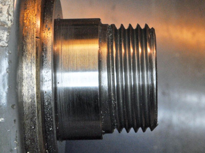
You have answered my next question, power ream or by hand, and given me enough other info to feel confident in doing this job. Reamer was ordered from RDG this afternoon and recently I bought some blue for just this purpose

                                              #309816
                                              Nige
                                              Participant
                                                @nige81730

                                                SteveI: Thank you, I understand your method though I do not have a flat piece of bar, would an appropriately sized piece of gauge plate do??

                                                The head stock on the ML4 is fixed by a central stud towards the rear with a nut on the top and two studs at the front with nuts underneath. Adjustment method is to slightly loosen the three nuts and 'persuade' the head stock in the appropriate direction before re-tightening. An recent attempt to see how this would work out resulted in having to use a G-clamp to wind the head stock sideways as tapping it with a copper hammer didn't seem to be doing the job with the headstock 'springing back'. I suspect that one or both of the two studs at the front might not be 'straight' and are preventing the head stock moving. I will try slightly rotating the studs to see if they 'straighten' up and leave space for movement. I will put a DTI on them to see how far out they might be.

                                                #309821
                                                SteveI
                                                Participant
                                                  @stevei

                                                  Nige,

                                                  The method relies on the flatness of the bar. Without a flat bar you would be struggling. Having said that if this method and some gauge plate allows you to get the head stock better aligned than you would otherwise then what is the harm? If you use it as best you can, the minimum benefit is that it will provide a sanity check for the alignment you measure with your MT2 test bar. There are largish ground parallel's for sale on ebay for not much. Are you in a club? I would expect a member that scrapes to knock you something up in less time than it took me to write these replies. A member with a surface plate would at the least allow you to find your flattest piece of gauge plate.

                                                  Brian has given excellent advice regarding the use of the mt2 hand reamer. In addition to that if you can get the spindle aligned then you can check the MT2 for run out and then when you ream it you can apply a little more pressure in the direction of the run out and at the same time have pressure in to the spindle you can make VERY small corrections. Having said that I would be very very careful if you choose to do that. It's easy to make it worse.

                                                  #309889
                                                  Howard Lewis
                                                  Participant
                                                    @howardlewis46836

                                                    Nige,

                                                    Once you have cleaned up the 2MT taper in the mandrel, BY HAND, you can fit your new 2MT Alignment bar.

                                                    Then, having mounted a D T I in the Toolpost, you set the clock on the centreline of the Alignment bar, before running the saddle up and down the bed.

                                                    As you adjust the position of the Headstock, the difference in readings between Headstock and Tailstock end should decrease until, hopefully, you reduce them to Zero. This will be a matter of checking, adjusting and rechecking again, and again, until you can get the Zero difference more than once.

                                                    Once you are certain that the Headstock is aligned, you fit dead centres (in good condition) to Mandrel and Tailstock, and with the Alignment bar held between centres, you start adjusting the Tailstock in like manner.

                                                    If your centres are obviously damaged, you mount each one in the now pristine 2MT Mandrel, in the freshly aligned Headstock, offset the topslide to 30 degrees, and clean up the centre. Repeat for the second one, before starting the Tasilstock alignment, as above..

                                                    The only time that you need the Tailstock off the centreline, is if you wish to turn a long taper. Short tapers can be produced by offsetting the Topslide.

                                                    HTH

                                                    Howard

                                                    #310069
                                                    Nige
                                                    Participant
                                                      @nige81730

                                                      Ok, today I went back to the workshop and fixed one of those parallels to the nose of the mandrel. tigtened gibs on saddle and cross slide to get rid of any play. Set up as below. ran Dial gauge back and forth about 2 1/2 inches and adjusted head stock until I had less than .01mm run out, remember this is at 90 degrees to the spindle. I thought that was pretty good.

                                                      spindle check1 (1).jpeg

                                                      I then turned the spindle 180 degrees and repeated the measurement only to find that the run out was .15mm !! Thinking about it I had not checked that the nose of the mandrel was actually 'flat, 90 degrees to the spindle axis'. I have probably managed to get the parallel to be parallel with the cross slide travel but nnot necasarily at 90 degrees to the axis of the bed.

                                                      I was also assuming that the parallel actually had all its relevant faces parallel to each other, a big assumption for an unknown tool. So, I wait for the MT2 finishing reamer to drop through the letter box and go to the next plan. I will also have a think about how I can check that the face of the mandrel nose is at 90 degrees to the mandrel axis

                                                      Again, your thoughts and suggestions are very welcome guys

                                                    Viewing 25 posts - 1 through 25 (of 56 total)
                                                    • Please log in to reply to this topic. Registering is free and easy using the links on the menu at the top of this page.

                                                    Advert

                                                    Latest Replies

                                                    Home Forums Manual machine tools Topics

                                                    Viewing 25 topics - 1 through 25 (of 25 total)
                                                    Viewing 25 topics - 1 through 25 (of 25 total)

                                                    View full reply list.

                                                    Advert

                                                    Newsletter Sign-up