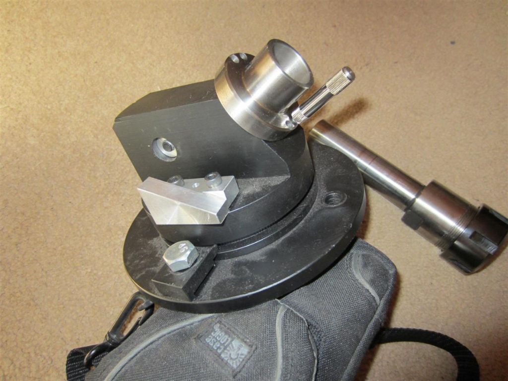
Milling machine to cutter grinder and 4 facet jig.

Advert

Milling machine to cutter grinder and 4 facet jig.

Home Forums Workshop Tools and Tooling Milling machine to cutter grinder and 4 facet jig.

Viewing 6 posts - 1 through 6 (of 6 total)
  • Author
    Posts
  • #381638
    Kevin D
    Participant
      @kevind

      Had this on the end of my first post. Should have started a new one.

      Thank you for your reply's. Please be patient the photo's to still be uploaded are post production.

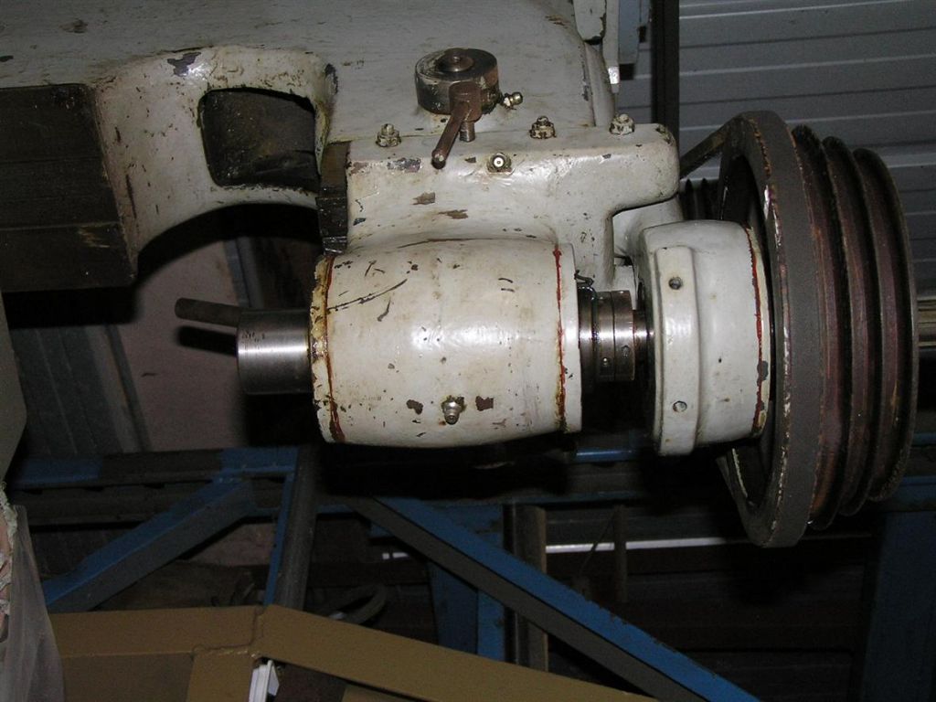
      I will combine the old mill conversion with the 4 facet grinding jig. The old mill was picked up at auction some time ago. M3 spindle on large taper roller bearings with a belt drive. The spindle head is on a vertical dovetail slide with a rack and pinion to raise and lower. A fine 3/8"bsf thread for spindle height / depth stop. p3100286.jpg

      The height over table was limited, so the pillar holding the knee adjusting nut was shortened. New acme table nuts were cut on the lathe. The old ones had worn to a whitworth profile. New lead screws made and the table re ground. As a mill using M3 collets it was very average. Lots of pounding on the draw bar to release the collets. Have use R8 ever since.

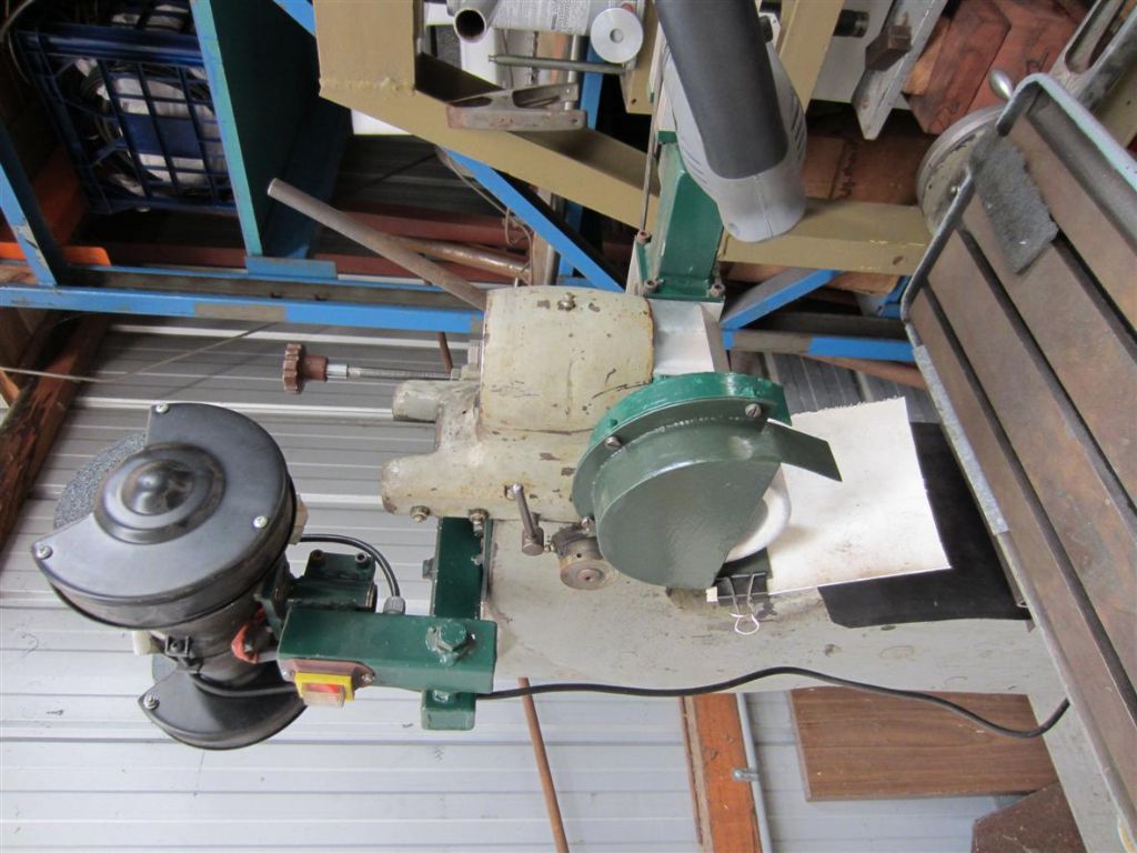
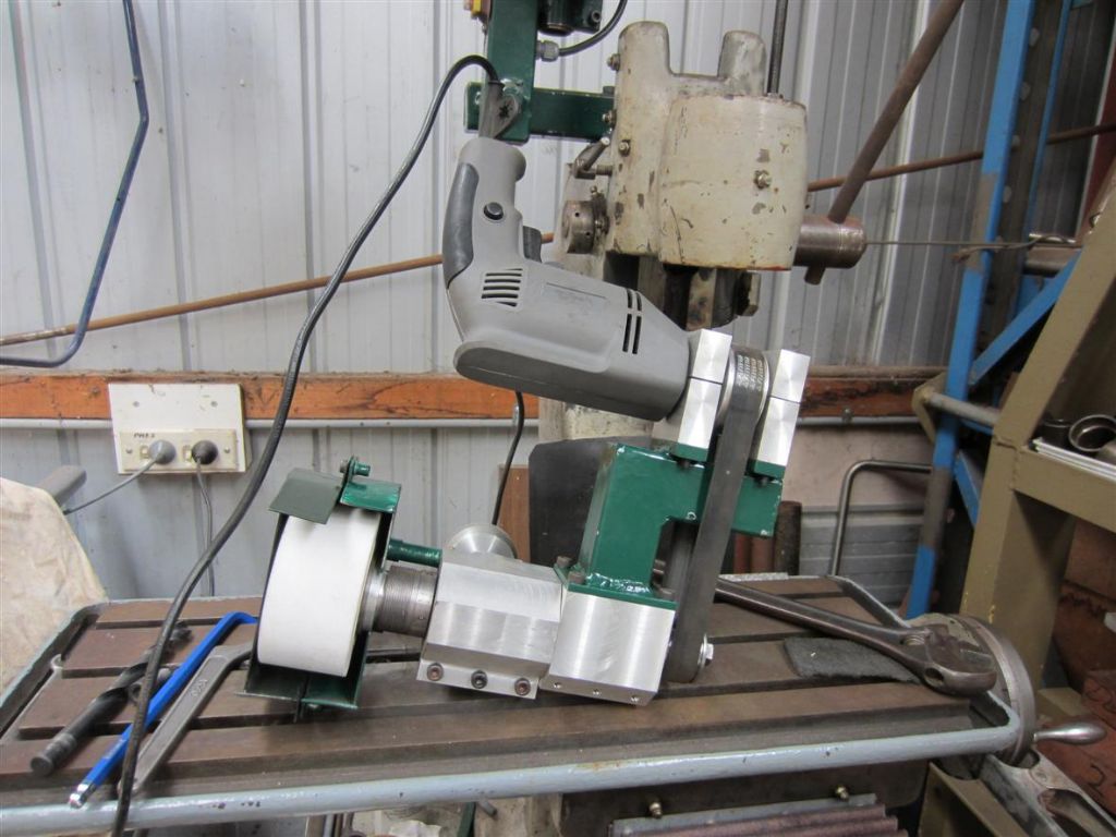
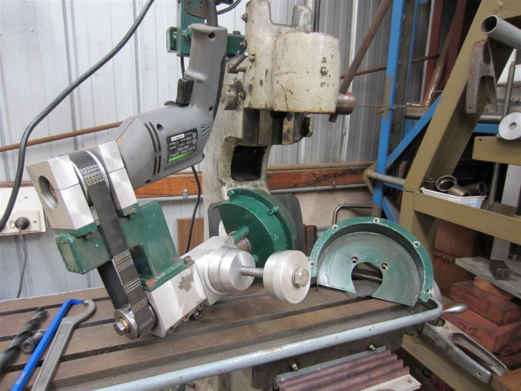
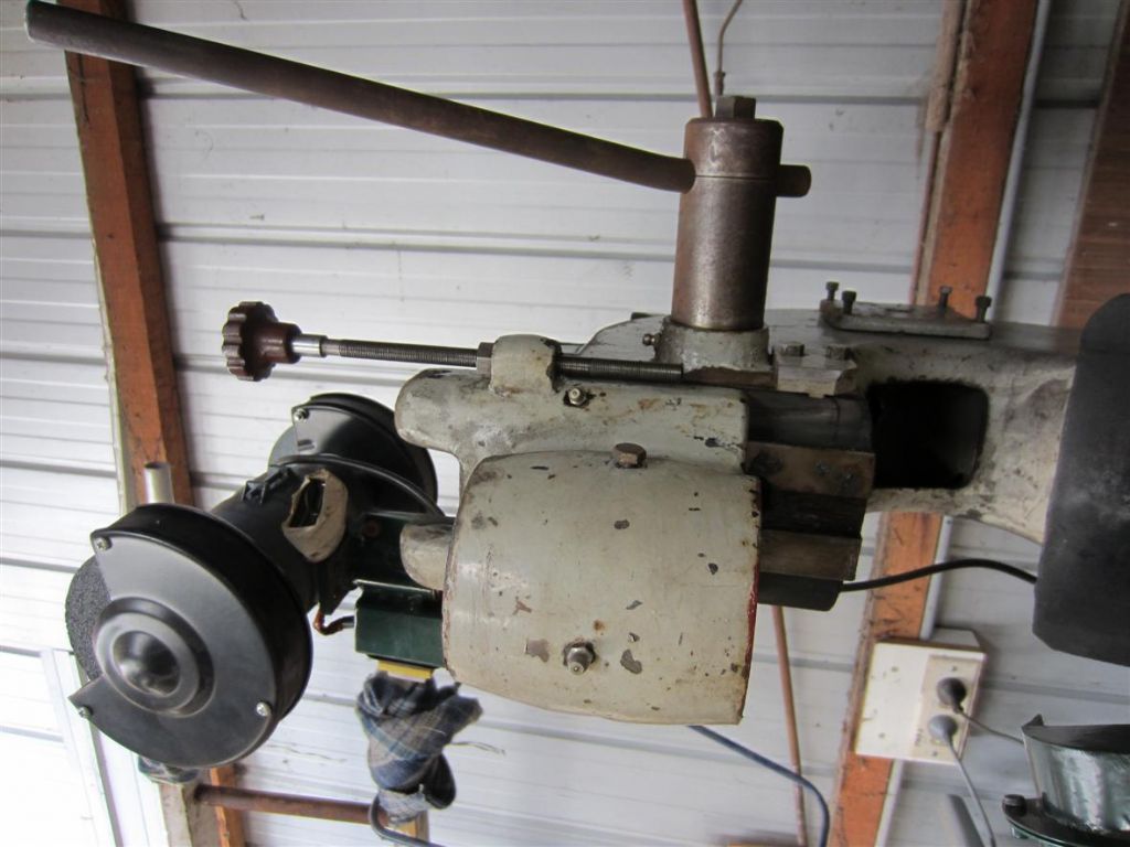
      A 50mm dia grinding spindle was made using taper roller bearings. Ref Workshop practice series No27. The original idea was to use a cheap Aldi 5" grinder to power it. After removing the gaiter springs from the oil seal each end it was still puffing and panting. More power was needed. A cheap pistol drill came to service. A flat belt pully was made to screw on instead of the chuck and the drill mounted by the universal round boss behind the chuck. Back to the mill. Remove the spindle and inner parts of the roller bearings. This leave two opposing tapered seats orientated vertical to the table with raise and lower movement and depth stop.

      A block of aluminium was bored 50mm for the spindle. At right angle to this a post with a male taper seat to match the bottom taper roller outer shell. A second taper seat was made to seat in top bearing shell. This gave a horizontal spindle which could be rotated about the vertical axis to a limited extent. img_0801.jpg

      img_0802.jpg

      img_0803.jpg

      img_0804.jpg

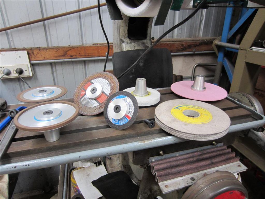
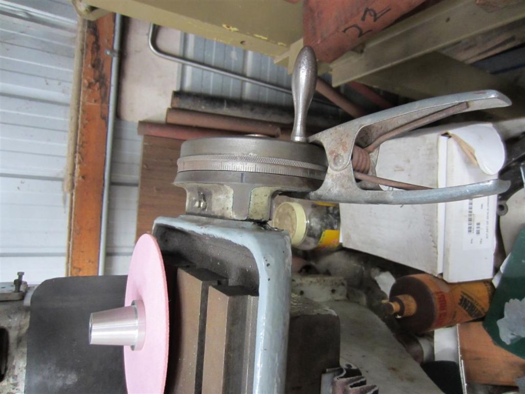
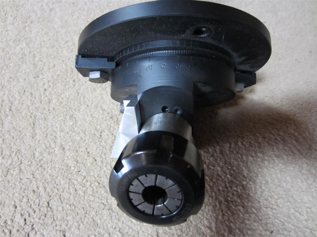
      The spindle is hollow with an ER32 socket and flat belt drive. The grinding wheels are mounted to the spindle in a similar manner to a Quorn, except an ER32 taper size in aluminium with a m10 draw bar is used. This allows the spindle to use wheels or cutters mounted in collets. img_0806.jpg

      The wheel is raised and lowered to grind with the x axis used to increase cut. Now this is good for the 4 facet jig. Cut one face and raise the wheel. Rotate 180 deg. and cut the other face without changing the table position. img_0808.jpg

      This may upset some readers but, I have a number of wheel mounts with worn angle grinder cutting disks. Cheap and quite ok for gear cutter grinding, the thin 1mm thick disks flex a lot, the 3mm ones are better. As the wheel moves at right angles to it's rotating axis the cut is on the outer edge.

      Advert
      #19141
      Kevin D
      Participant
        @kevind
        #381639
        Kevin D
        Participant
          @kevind

          Second part.

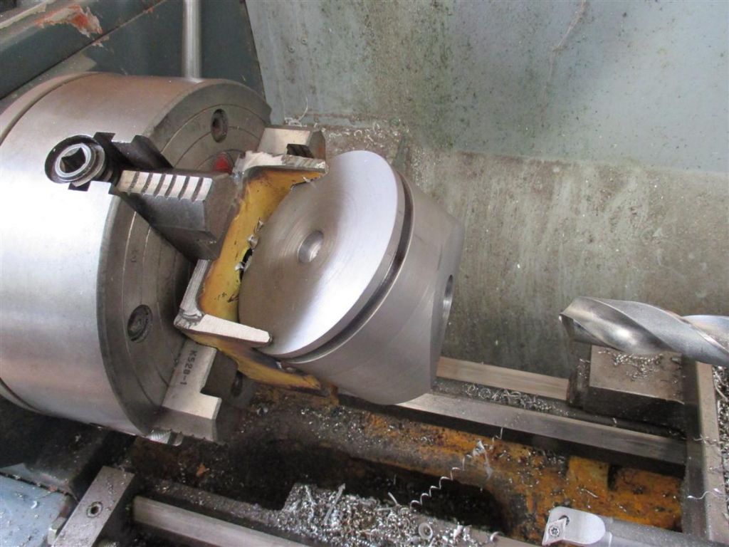
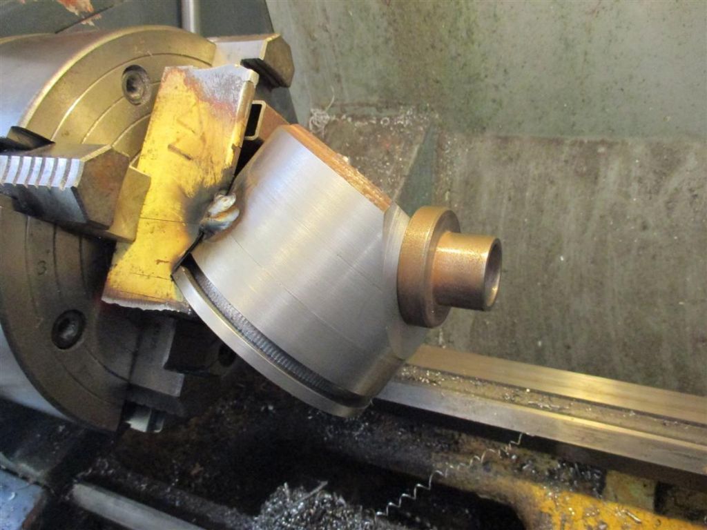
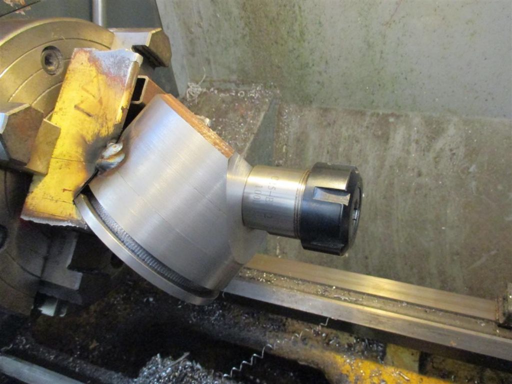
          The 4 facet jig is base on Les Riley's design (MEW Feb 2006). The body 110dia by 80 long steel. This was welded to a short piece of 3" channel at an angle of 59deg. img_0080.jpg

          img_0083.jpg

          img_0085.jpg

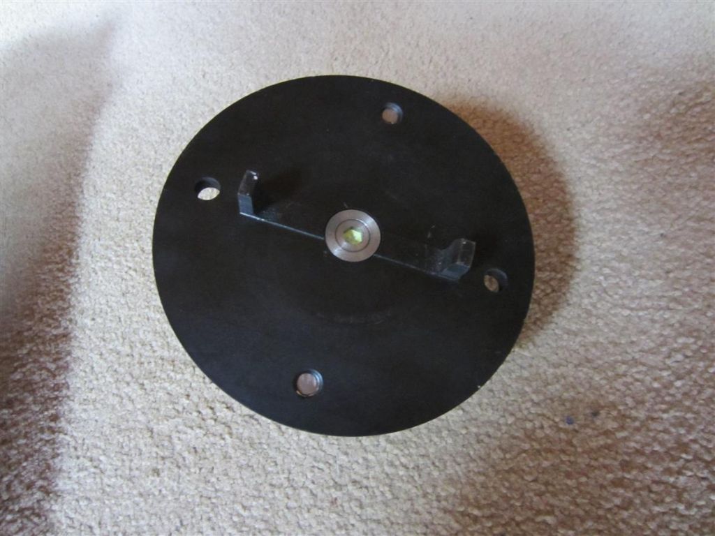
          Mount in a 4 jaw and machine the angled face, bore 25dia. at an angle of 31deg. Cut off channel and dress outside, dress base and leave a small spigot to locate centre. The 6×6 groove allows clamps like those on the rotary tables. Now a few hours on the shaper to cut each side. The ER32 collet chuck with a 25 dia parallel shank has two flats on the body. A perfect location to give 180 deg rotation, an aluminium clamping plate locates on the flats. The clamping plate also has a surface at 22.5deg. on the other side. Reverse the plate to get the rotation for the sixth facet. img_0832.jpg

          img_0834.jpg

          img_0835.jpg

          A M3 holder was machined up with a 25die shank for large drills. This has pin location similar to the original design.

          The base was a cast iron pipe flange, the locating spigot was machined to give table slot location.

          And now a question. At what size do you have to change to 6 facets. I am still having some fun getting parallel primary facets. This must be due to the drill rotated slightly off vertical cutting edges in the jig.

          All the parts were modeled on Varicad 3D prior to machining. I have uploaded most of the photo's, look in the album's for more.

          #381643
          Chris Evans 6
          Participant
            @chrisevans6

            I am most impressed, looks like a lot of folk will need to increase their winter workshop time.

            #381645
            Michael Gilligan
            Participant
              @michaelgilligan61133

              Thanks, Kevin yes

              Good stuff: Keep it coming …

              MichaelG.

              #381646
              Brian H
              Participant
                @brianh50089

                Very impressive.

                Brian

              Viewing 6 posts - 1 through 6 (of 6 total)
              • Please log in to reply to this topic. Registering is free and easy using the links on the menu at the top of this page.

              Advert

              Latest Replies

              Viewing 25 topics - 1 through 25 (of 25 total)
              Viewing 25 topics - 1 through 25 (of 25 total)

              View full reply list.

              Advert

              Newsletter Sign-up