Meshing with Lantern pinions – Part A

Advert

Meshing with Lantern pinions – Part A

Home Forums Clocks and Scientific Instruments Meshing with Lantern pinions – Part A

Viewing 4 posts - 1 through 4 (of 4 total)
  • Author
    Posts
  • #3832
    Sam Stones
    Participant
      @samstones42903

      Another slice of CAD and how cycloidal clock teeth might mesh

      Advert
      #406109
      Sam Stones
      Participant
        @samstones42903

        What started as a simple (CAD) depthing exercise between the wheel teeth and pinion leaves of John Wilding’s large wheel (290 x 8) skeleton clock, turned into a rather protracted undertaking.

        See here … **LINK**

        There were complimentary hints too, that I should instead direct it for M.E. publication. However, for various reasons I am no longer attracted to the idea. I had already enjoyed (and struggled) with submitting three articles and have a clear idea of how much work is involved.

        As mentioned in other places, I have never carried out a practical depthing exercise of gear wheels/pinions. Perhaps I was lucky enough to get away with drilling the pivot holes in the skeleton clock plates even before I had cut the wheels, pinions and arbors. However, following John Stevens’ design, the clock has been running since about 2011.

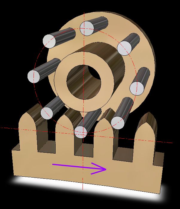
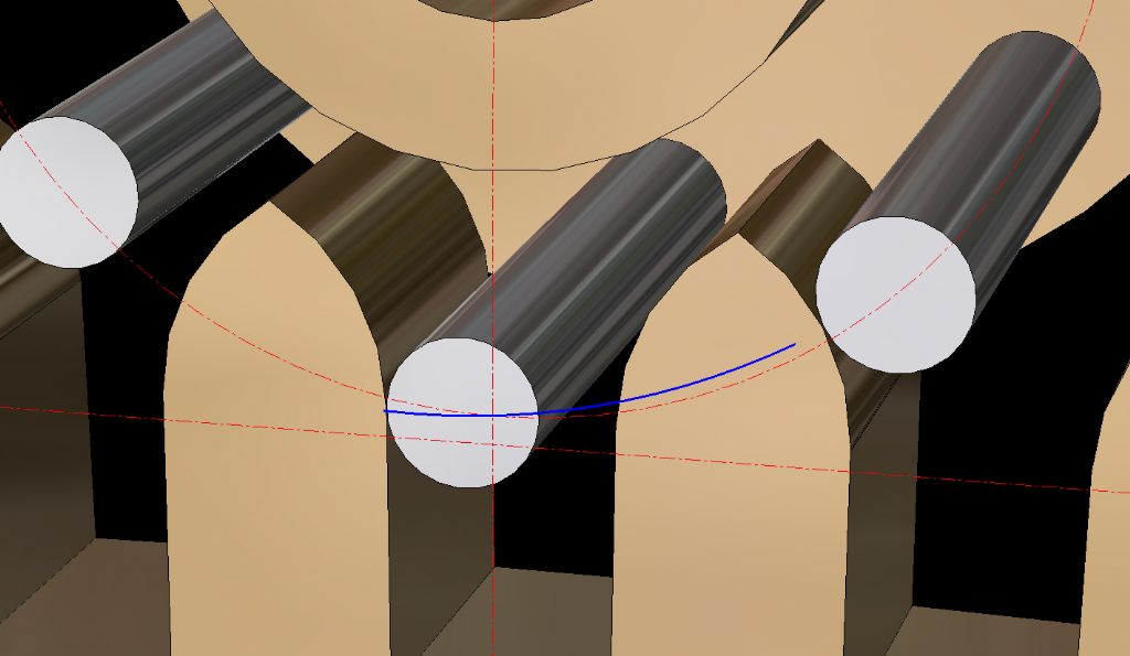
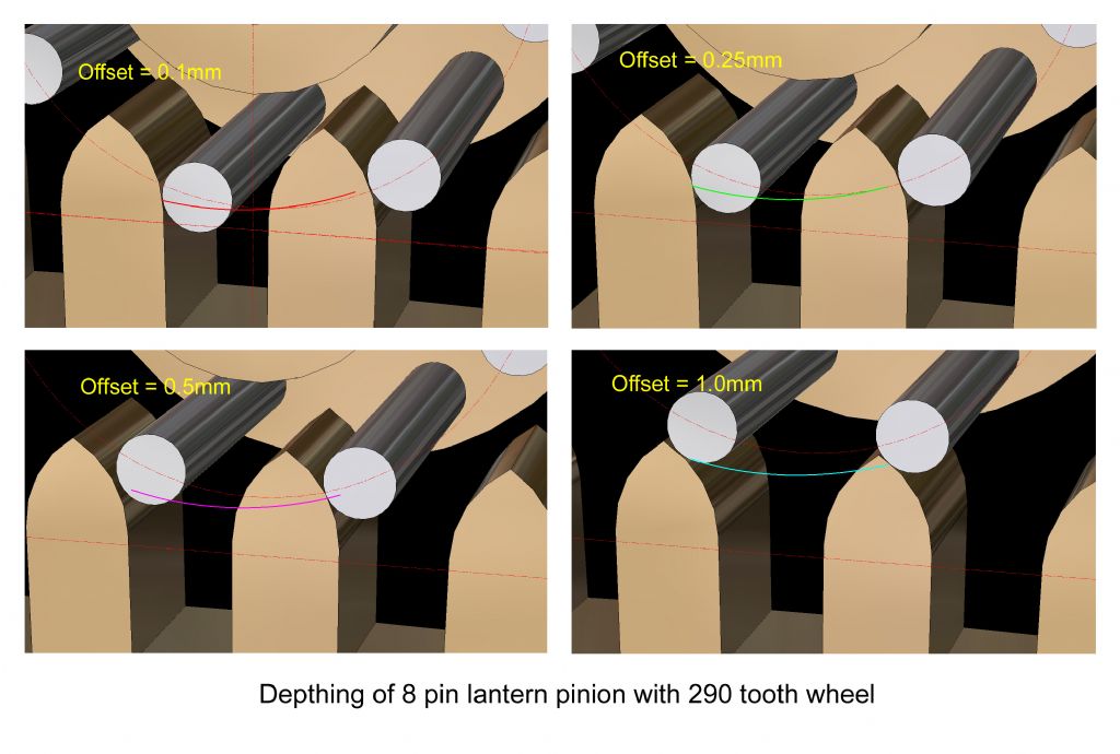
        In conjunction with the meshing details in the previous thread, and Michael Gilligan’s interesting suggestion, these latest images show how an 8pin lantern pinion would mesh with the large (290tooth) wheel (refer John Wilding’s ‘Large wheel skeleton clock).

        As before, I constructed the wheel teeth according to ‘involute’ data via BS 978: Part 2. The diameter of the lantern pins matches the thickness of the pinion leaves in the previous thread. Obviously, the front disc of the lantern pinion is missing for clarity.

        As before, this series includes meshing-depth decreases from ‘on centre’ to include offset of 0.1mm, 0.25mm, 0.5mm, and 1.0mm. The wheel teeth drive the (pinion) pins to the right.

        8-290---full-image---on centre line.jpg

        8-290---lantern---on centre line---close-up.jpg290-&-8---lantern---meshing---offset---0.1mm---1.jpg

        This is incomplete. Please go to Part B

        Sam smile d

        #406118
        Michael Gilligan
        Participant
          @michaelgilligan61133
          Posted by Sam Stones on 23/04/2019 00:45:29:

          As before, I constructed the wheel teeth according to ‘involute’ data via BS 978: Part 2.

          .

          Sam,

          Many thanks for doing this follow-up yes

          Before I proceed to study Part B though; may I just check what appears to be a typo screaming out at me …

          Hopefully 'involute' should read 'cycloidal'

          MichaelG.

          #406205
          Sam Stones
          Participant
            @samstones42903

            Definitely a significant error of mine Michael. crying

            Thanks for bringing it to my attention, and apologies to all.

            Cycloidal NOT involute!

            It's time this SOB packed his bags.

            Sam embarrassed

          Viewing 4 posts - 1 through 4 (of 4 total)
          • Please log in to reply to this topic. Registering is free and easy using the links on the menu at the top of this page.

          Advert

          Latest Replies

          Viewing 25 topics - 1 through 25 (of 25 total)
          Viewing 25 topics - 1 through 25 (of 25 total)

          View full reply list.

          Advert

          Newsletter Sign-up