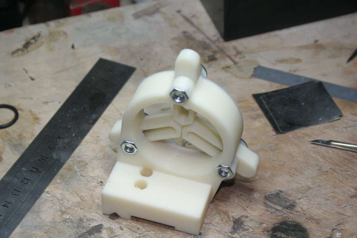
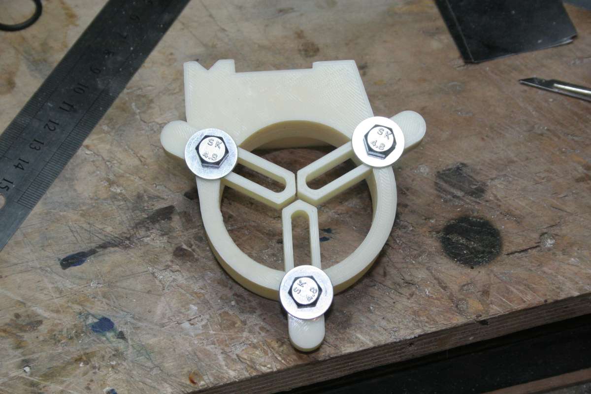
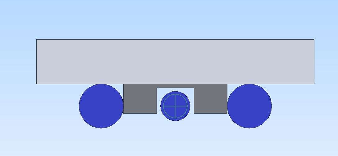
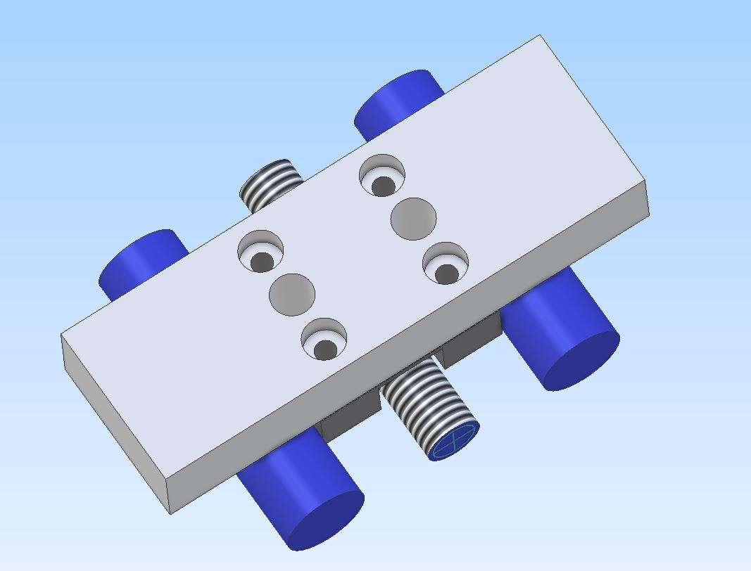
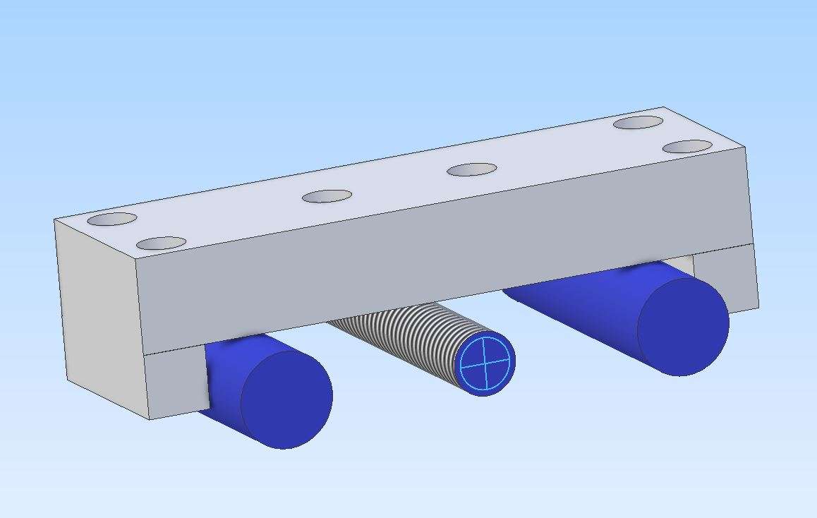
Making Unimat DB/SL Steadies
Making Unimat DB/SL Steadies
- This topic has 39 replies, 12 voices, and was last updated 20 August 2025 at 09:25 by
 Michael Gilligan.


- Please log in to reply to this topic. Registering is free and easy using the links on the menu at the top of this page.
Latest Replies
-
- Topic
- Voices
- Last Post
-
-
Granville lathe leadscrew change wheel
Started by:
JACK SIDEBOTHAM
in: Help and Assistance! (Offered or Wanted)
- 4
-
20 August 2025 at 12:57
John Hinkley
-
Phone Phreaking
Started by:
Michael Gilligan
in: Clocks and Scientific Instruments
- 5
-
20 August 2025 at 12:41
Robert Atkinson 2
-
Greatest Model Engineer
Started by:
Juddy
in: The Tea Room
- 17
-
20 August 2025 at 12:37
John MC
-
Softening epoxy
Started by:
John Haine
in: General Questions
- 8
-
20 August 2025 at 12:32
Robert Atkinson 2
-
Material advice
Started by:
tobyonekenobi
in: Materials
- 2
-
20 August 2025 at 11:58
tobyonekenobi
-
Use of Hydrostatic lubrication in steam locomotives
Started by:
Greensands
in: Locomotives
- 6
-
20 August 2025 at 10:50
duncan webster 1
-
Harold Hall – 1933 -2024
Started by:
Neil Wyatt
in: Website Announcements
- 13
-
20 August 2025 at 10:44
scotland63
-
Reference lines for dimensions – Fusion 360
Started by:
John McCulla
in: CAD – Technical drawing & design
- 5
-
20 August 2025 at 10:12
John McCulla
-
Cheap DRO
Started by:
Steve355
in: General Questions
- 11
-
20 August 2025 at 09:48
John Hinkley
-
Opposed Piston Engines
1
2
Started by:
Richard Simpson
in: The Tea Room
- 13
-
20 August 2025 at 09:42
Howard Lewis
-
Making Unimat DB/SL Steadies
1
2
Started by:
Andy Carlson
in: Workshop Techniques
- 12
-
20 August 2025 at 09:25
Michael Gilligan
-
The stand alone weight for tower clock
Started by:
dk0
in: Clocks and Scientific Instruments
- 8
-
20 August 2025 at 08:33
John Haine
-
Steam driven air pump for brakes
Started by:
Werner Schleidt
in: Locomotives
- 10
-
20 August 2025 at 08:05
Werner Schleidt
-
End Mill Sharpening Jig
Started by:
Vic
in: Workshop Tools and Tooling
- 6
-
19 August 2025 at 23:02
Nigel Graham 2
-
Horwich Crab
Started by:
Michael Foster
in: Locomotives
- 2
-
19 August 2025 at 22:17
Dave Wootton
-
Kuroda Boring & Facing head
Started by:
Oily Rag
in: Workshop Tools and Tooling
- 7
-
19 August 2025 at 20:49
ryan.carter848
-
Solar panel
Started by:
duncan webster 1
in: Electronics in the Workshop
- 4
-
19 August 2025 at 20:37
martin haysom
-
Any suggestions
Started by:
Vic
in: The Tea Room
- 6
-
19 August 2025 at 17:53
DMB
-
New Compressor
Started by:
Andy Brocklehurst
in: General Questions
- 16
-
19 August 2025 at 17:13
not done it yet
-
St Albans Big Show 27 & 28 Sept 25
Started by:
Bazyle
in: Exhibitions, Shows and Club Events
- 2
-
19 August 2025 at 14:20
Bo’sun
-
Backplate
Started by:
Steve355
in: General Questions
- 10
-
19 August 2025 at 13:12
JasonB
-
My week this week! My workshop videos
1
2
…
11
12
Started by:
Phil Whitley
in: The Tea Room
- 16
-
18 August 2025 at 17:20
vic newey
-
Who’s to be trusted ?
1
2
Started by:
Michael Gilligan
in: Electronics in the Workshop
- 18
-
18 August 2025 at 16:01
HOWARDT
-
NU tool milling machine
Started by:
joseph tatler
in: Manual machine tools
- 7
-
18 August 2025 at 11:11
Martin Connelly
-
Model Engineer Magazine Collection
Started by:
mfengine1
in: Books
- 10
-
18 August 2025 at 09:33
bcaddle62
-
Granville lathe leadscrew change wheel


