Machining a cast wheel what do you grip first?

Machining a cast wheel what do you grip first?

Home Forums Beginners questions Machining a cast wheel what do you grip first?

Viewing 16 posts - 1 through 16 (of 16 total)
  • Author
    Posts
  • #9219
    Nige
    Participant
      @nige81730
      #357532
      Nige
      Participant
        @nige81730

        This question prompted by seeing a photo of a cast flywheel that will be machined. I can see that it will need a hole in the boss and the outer rim machining but where do you start, which part do you assume is 'accurate'? Do you hold it by the boss and turn the rim then hold the rim and drill the boss? Which bit do you rely on being 'near enough correct' to use as the starting point?

        Thanks, Nige

        #357534
        Clive Brown 1
        Participant
          @clivebrown1

          I would normally hold it in the 4-jaw by the inside rim and set the "as-cast" inside rim as true as possible. The outer rim, boss and bore can then be machined. This approach might need to be modified, dependant on the exact geometry

          #357537
          Hopper
          Participant
            @hopper

            Haha, yes it's a bit of a chicken and egg situation. One common way of doing it is to hold the outer rim in the four jaw chuck with the jaws reversed and the outer rim set to run as true as you can get a rough casting to run. (Say within 10 thou to 1/64" or so). You first face off the boss and turn the boss OD if required, then drill and bore/ream the centre hole.

            You can then mount the flywheel on an arbor that the hole in the boss is a tight fit onto. Either by way of a very slight taper or a spot of Loctite. This arbor is turned to size between centres first. So then when the flywheel is mounted on the arbor, the arbor is put up between centres with a driving dog to turn it. You then machine the outer rim on the OD and both sides. This makes sure the rim runs true when the finished flywheel is mounted to the model engine crankshaft.

            But there are other ways. EG, you can mount the flywheel on the faceplate, clamped by the spokes with a round ring spacer (such as ball bearing outer race) between the spokes and faceplate. Set the rim to run as true as possible. Then machine the rim OD, rear face and front face. Then machine the boss and drill and bore/ream the hole in the middle, all in one set up so all surfaces run concentric and true to each other.

            I have also done it by machining the face and OD of the boss and then holding the boss in the lathe chuck, with a tailstock centre in place. Machine the rim OD and rim faces and then drill and bore/ream the hole in the boss in one set up. This ensures the rim runs true to the hole in the middle but the OD of the boss may have a small runout, not particularly critical usually.

            Take your pick. The important thing is to machine the rim OD and faces in the same setup as the hole in the middle so they all run true to each other — except for method 1 where the arbor ensures trueness between hole and rim.

            #357543
            Nige
            Participant
              @nige81730

              Thank you Clive and Hopper, comprehensive replies that explain it all. I realised that rim, boss and bore needed to be concentric but hadn't quite fathomed how that might be achieved and you guys have given me a couple of new techniques to try and store in memory 😊 though I try and make the titles of my queries useful with words I can search on later 👍 Again, thank you.

              Nige

              #357555
              Hopper
              Participant
                @hopper

                You're welcome. Have fun!

                #357557
                JasonB
                Moderator
                  @jasonb

                  I usually do it as Clive says but it does depend on the diameter of the flywheel and also the number of spokes as both can make it impossible to get the 4 jaws into position, 5 spoke flywheels are usually the worse for this.

                  #357577
                  Paul Lousick
                  Participant
                    @paullousick59116

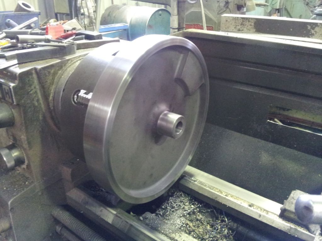
                    I mounted the flywheel for my engine in a 4-jaw chuck by the inside of the flange, then machined the bore, outer surface of the boss and the outside and one side of the flange. This ensured that they were all machined on the same centre.

                    The chuck jaws were centred on the inside of the flywheel and the OD made concentric with it. The inside flange on my flywheel is a cast surface. If I had located on the OD, I probably would have to machine the ID to make it concentric and balanced. (also a bit difficult with couterbalance weight built into the casting)

                    The flywheel was then reversed and held by the boss to machine the remaining side of the flange.

                    Paul

                    flywheel (large).jpg


                    Edited By Paul Lousick on 13/06/2018 12:45:57

                    #357644
                    geoff walker 1
                    Participant
                      @geoffwalker1

                      Nigel

                      Tubal cain video on you tube shows how to machine a stuart progress engine flywheel.

                      Might be of interest to you, it's in part 3

                      Google making a stuart progress engine and you will find it.

                      geoff

                      #357656
                      Anonymous

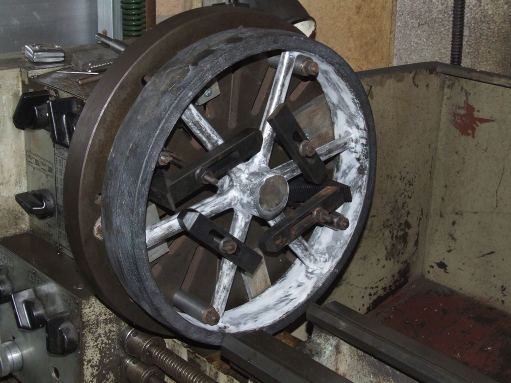
                        If the flywheel is too big for the chuck a faceplate comes in handy:

                        flywheel_setup.jpg

                        As said, line up by eye on the inner edge of the rim. It looks odd if the rim thickness varies widely and is potentially dangerous, but nobody cares if the boss is a bit eccentric.

                        Side Note: Most of my work bosses haven't been eccentric, just incompetent. sad

                        Andrew

                        #357670
                        Neil Wyatt
                        Moderator
                          @neilwyatt

                          Clive's approach has a lot of appeal as the inside rim can't be machined and an uneven or offset inside rim is more noticeable than an slightly offset hub.

                          However you approach it, the aim hold be to get the unmachined parts of the casting as concentric as possible.

                          Neil

                          #357675
                          Zan
                          Participant
                            @zan

                            What ever method you use machine the bore and rim at the same setting to avoid wobble. Avoid using an arbour, the bore is usually too small to resist the cutting firces at such a distance to the rim

                            #357676
                            duncan webster 1
                            Participant
                              @duncanwebster1

                              +1 for Paul's method, it's how I machined the driving wheels for 2 of my locos, but I did mount them from the OD and skim the ID of the rim first to give the 4 jaw a decent surface to grip. you need surprisingly little length to get a really firm hold with a 4 jaw. If you machine the OD and bore at the same setting it can't be wrong! making jigs to centralise te bore is just wasting time, and I have little enough of that.

                              Edited By duncan webster on 13/06/2018 23:12:17

                              #357694
                              JasonB
                              Moderator
                                @jasonb

                                When it comes to the bore it can go wrong even when machining at the same setting. To avoid wobble it is always better to drill and then bore to final size rather than drill and ream.

                                A drill can run off particularly in a casting where there may be flaws, harder spots etc and the average reamer will follow that hole plus give a sliding fit where you really want a push fit particularly if using a tapered gib head key to retain the flywheel.

                                Edited By JasonB on 14/06/2018 07:00:34

                                #357696
                                bricky
                                Participant
                                  @bricky

                                  I am making two flywheels from 20mm plate,the sizes are 4.834" with a bore of 12mm.I have cropped the plate to give me a hexagon to start with and as I have to make an arbour to carry the gear on the crankshaft which is the same bore I made this to be a push fit in the bearings.I used a sharp HSS bit to do the interupted cutting and then when that was finished I used a tipped tool.I then faced down to the washer to give me a flat surface to hold in the four jaw chuck then I can profile the rest of the flywheel.I had to make a reamer from mild steel as I had no silver steel of 12mm and then I case hardened it twice and it worked a treat.Hopefully no wobble.

                                  Frank

                                  #357698
                                  Paul Lousick
                                  Participant
                                    @paullousick59116

                                    The flywheel on my engine is secured with taperred keys and a tapered slot had to be cut into the boss in the flywheel.

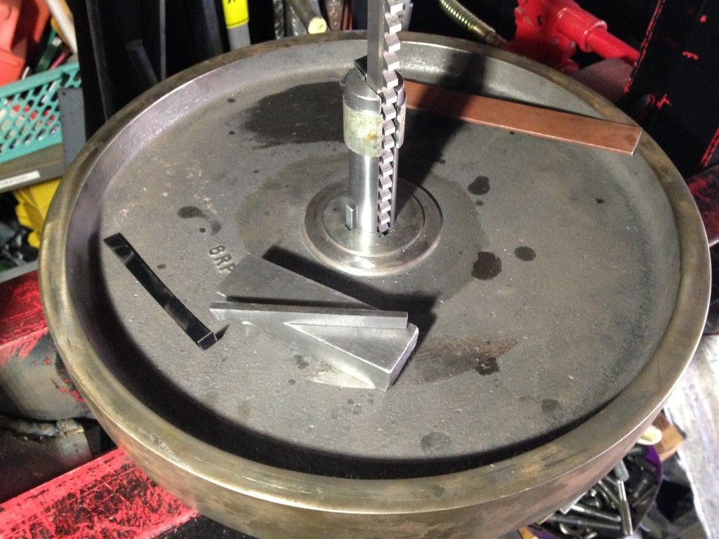
                                    I first cut a keyway with a broach. Pushing the broach thru the flywheel with a press and then making subsequent passes with shims behind the cutter to deepen the keyway slot. The final cuts were made with a taperred shim behind the broach to make the angled slot. I then made a key by using the same taperred shim under the key material. Both key and keyway were then at the exact same angle.

                                    Securing a flywheel to the shaft with a taperred key is fairly simply but my engine has 2 keys at 90 degrees to each other. A bit more complex. The solution was to make a broach guide that was a slide fit with the flywheel bore and machine 2 slots in it at 90 degrees to each other. One to locate in the first slot in the flywheel with a key and the second slot as a guide for the broach to cut a second slot.

                                    Paul.

                                    flywheel keyway.jpeg

                                  Viewing 16 posts - 1 through 16 (of 16 total)
                                  • Please log in to reply to this topic. Registering is free and easy using the links on the menu at the top of this page.

                                  Latest Replies

                                  Home Forums Beginners questions Topics

                                  Viewing 25 topics - 1 through 25 (of 25 total)
                                  Viewing 25 topics - 1 through 25 (of 25 total)

                                  View full reply list.