Lathe run out

Advert

Lathe run out

Home Forums General Questions Lathe run out

Viewing 25 posts - 51 through 75 (of 77 total)
  • Author
    Posts
  • #547101
    Ian Bowers
    Participant
      @ianbowers85137

      Just for info the horizontal alignment of the headstock is normally adjustable on these lathes, I had to align my Bailiegh PL1340 headstock as when turning a piece of 50mm aluminium it was about 0.1 mm out over 150mm!

      The lathe was second hand but hardly used. There are jacking screws on the back of the headstock to help.

      ian

      Advert
      #547102
      Robin
      Participant
        @robin

        Still waiting for parts I have been trying to come up with some test I can apply while I screw adjust the feet.

        I put in a wiggler to project the spindle rotation axis to the far end of the bed.

        Then view from above and from the side with digi-cam…

        It seems to be improving all by itself but I think it will twist wildly out of shape the moment I stress it.

        It needs to be locked down face 1

        #547117
        Hopper
        Participant
          @hopper

          That long thin bar is so flexible it is telling you nothing reliable. Stick with the standard tests as described.

          #547124
          Robin
          Participant
            @robin
            Posted by Hopper on 25/05/2021 22:56:54:

            That long thin bar is so flexible it is telling you nothing reliable. Stick with the standard tests as described.

            I'm not so sure… the wiggler tip is steady in the same position whether spinning or not. It has to be on the spindle axis. There is no other sensible place it could be.

            I just dropped the tailstock down to alignment by taking it out and cleaning it below with Scotchbrite, brake cleaner and a roll of kitchen towel. Vast amounts of foundry sand, cast iron dust and Gobi desert replaced with clean oil.

            I will have to take the saddle off and give it the same treatment before I can trust it, before it grinds my bed down to unuseable face 22

            #547127
            Robin Graham
            Participant
              @robingraham42208

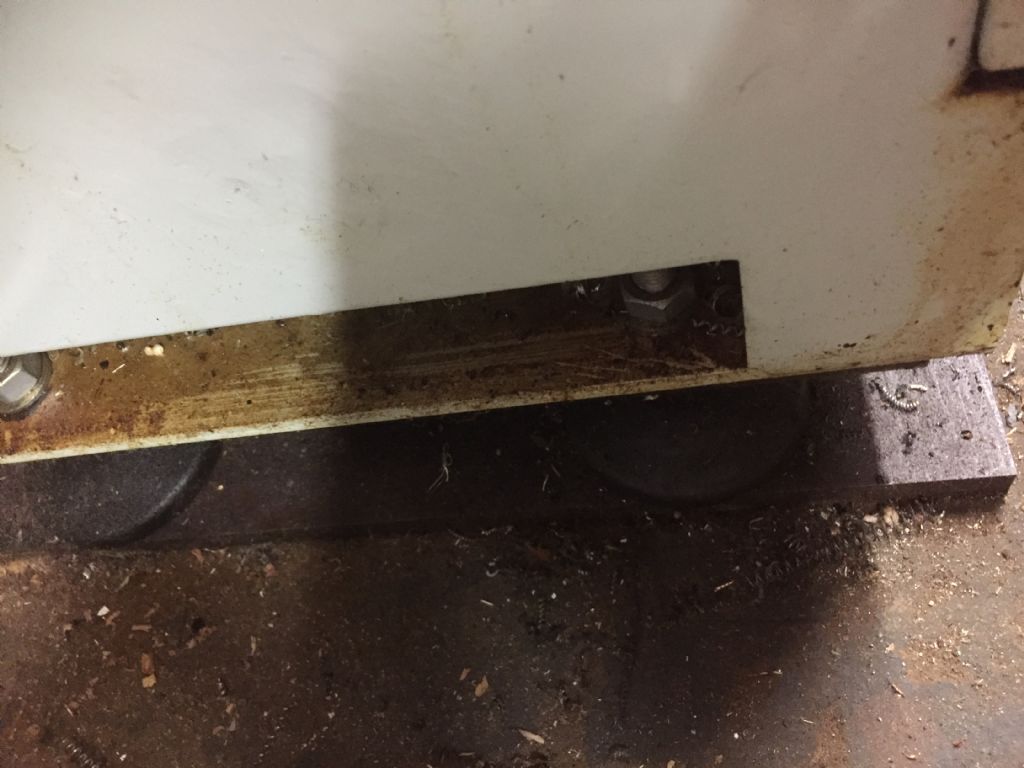
              Robin, I have a very similar lathe, albeit Axminster branded. It sits on the wonky flagstones of a 200 year old cellar, using eight (four per pillar) 80mm diameter rubber feet on M12 studs (I got them from WDS I think):

              lathefeet.jpg

              I was lucky enough to have to have the generous help of a professional engineer (the late John Stevenson) in setting the machine up. He spent half an hour muttering, twiddling the nuts and checking the ways with a level before announcing 'that's good enough'. No shimming or anything like that, and it was indeed 'good enough' – it turns parallel between centres to < 0.01mm over 400mm. The lathe weighs about 600kg, of which I reckon about 100-120 kg is in the stand and the rest in the machine – so it's the tail wagging the dog – but it seems to work.You'll get there! It won't twist after it's been set up properly – at least mine hasn't.

              Your method of projecting the spindle axis by holding a piece of what looks like rolled BMS in a 3-jaw is, unfortunately, not good . For starters, the bar cannot be relied on to be round/straight and the chuck won't hold the bar dead on axis anyway. Then there's gravity. You need to think about what exactly you're measuring and why. And re-read what others have said upthread.

              Another Robin.

              #547132
              Robin
              Participant
                @robin

                That looks familiar wink

                It's a nice machine, just needs a bit of fettling. You chose well yes

                #547133
                Hopper
                Participant
                  @hopper
                  Posted by Robin on 25/05/2021 23:45:58:

                  Posted by Hopper on 25/05/2021 22:56:54:

                  That long thin bar is so flexible it is telling you nothing reliable. Stick with the standard tests as described.

                  I'm not so sure…

                  I am. (Based on 50 years of aligning machinery ranging from sewing machines to power station turbines. )

                  Plus, if the headstock spindle is a tad out of alignment with the as-yet unaligned bed, at the end of that four foot bar it's going to be waaaaay out. Which puts your tailstock alignment out by the same amount if you set it to the wiggler point.

                  Do what the professionals do, set your tailstock alignment as close to the chuck as possible. Preferably after the bed has been aligned.

                  And please be very careful spinning that unsupported bar under power. It can bend and whip around with catastrophic results if spun at more than absolute snails pace.

                  #547147
                  Martin Connelly
                  Participant
                    @martinconnelly55370

                    The department I supported at work (RGT then EGT then eventually Siemens) used alignment mandrels for years, we had to make them as large a diameter as possible because of sag. We calculated the effects of diameter and material and wall thickness to get them to have as low a sag as possible but it was always there. We ended up with aluminium alloy mandrels with diameters that reduced along their length, staring off about Ø200 then a section of about Ø150 until we had a mag base type rod in the end. The sag was lowest when the diameter was as large as possible and wall thickness did not need to be very high. As soon a laser alignment became available we bought into it immediately. So I have to say Hopper is 100% correct here, your long and slender mandrel will have measurable sag that will be there regardless of spinning or not. So side to side may be OK but up and down no chance.

                    Machine tool setting was done with optical systems for years to avoid sag like this and we had one at work that we could not use on most of our setups because of there being no way to mount it. When we got the laser based systems we gave the optical system to the local astronomy society.

                    Martin C

                    #547150
                    Michael Gilligan
                    Participant
                      @michaelgilligan61133

                      Further to Martin’s note … It’s worth looking at Dr Schlesinger’s little book:

                      Testing Machine Tools

                      Downloadable, thanks to our editor’s alter-ego, here: **LINK**

                      http://www.stubmandrel.co.uk/workshop/13-dr-schelsinger-s-limits

                      Jump to page 9 of the book.

                      MichaelG.

                      #547159
                      Hopper
                      Participant
                        @hopper

                        Although, Schlesinger is probably way too much information to be of much use to a beginner. But perhaps nice to know the background and just how far you can disappear down the rabbit hole if so inclined.

                        The other "bible" if you are interested in such things is the classic book "Machine Tool Reconditioning" by Edward Connelly. It is more of a hands-on "how to" book for shop-floor machine tool fitters. But not available for free download and getting expensive to buy in hard copy these days. I bought mine in the US in the 1980s for what seems a laughable pittance today.

                        As I pointed out before, the Myford ML7 User's Manual PDF is available for free and has all the home hobbyist needs to know about setting up a new lathe in good condition to turn parallel. It's a very basic process if you stick to it.

                        #547162
                        Michael Gilligan
                        Participant
                          @michaelgilligan61133
                          Posted by Hopper on 26/05/2021 09:20:00:

                          Although, Schlesinger is probably way too much information to be of much use to a beginner. But perhaps nice to know the background and just how far you can disappear down the rabbit hole if so inclined.

                          […]

                          .

                          … Which is why I wrote:

                          Further to Martin’s note: … Jump to page 9 of the book.

                          That short section is important, and Schlesinger apparently had it sussed in 1902

                          MichaelG.

                          #547163
                          Martin Connelly
                          Participant
                            @martinconnelly55370

                            The department I supported at work (RGT then EGT then eventually Siemens) used alignment mandrels for years, we had to make them as large a diameter as possible because of sag. We calculated the effects of diameter and material and wall thickness to get them to have as low a sag as possible but it was always there. We ended up with aluminium alloy mandrels with diameters that reduced along their length, staring off about Ø200 then a section of about Ø150 until we had a mag base type rod in the end. The sag was lowest when the diameter was as large as possible and wall thickness did not need to be very high. As soon a laser alignment became available we bought into it immediately. So I have to say Hopper is 100% correct here, your long and slender mandrel will have measurable sag that will be there regardless of spinning or not. So side to side may be OK but up and down no chance.

                            Machine tool setting was done with optical systems for years to avoid sag like this and we had one at work that we could not use on most of our setups because of there being no way to mount it. When we got the laser based systems we gave the optical system to the local astronomy society.

                            Martin C

                            #548294
                            Robin
                            Participant
                              @robin

                              Well of course I tried it my way first, dismal failure.

                              Then I fixed the Engineers' level, removed the bodge piece of folded Chinesium, redrilled the scale pivot to square, put it back together again.

                              Then I levelled the bed. The tiniest tweak on any foot changes everything, took hours dont know

                              The largest bar I had was about 1.5" diameter. The chatter was decorative at the end but I got 6" of smooth.

                              Left hand end 1.5712"

                              Right hand end 1.5709"

                              Error 0.0003"

                              Bliss yes

                              #548310
                              Martin Kyte
                              Participant
                                @martinkyte99762

                                If you bturn a waist on your bar so you have 2 'collars' at either end you only need to turn those for your test. instead of traversing down the entire length.

                                regards Martin

                                #548331
                                Tony Pratt 1
                                Participant
                                  @tonypratt1
                                  Posted by Martin Kyte on 04/06/2021 16:10:29:

                                  If you bturn a waist on your bar so you have 2 'collars' at either end you only need to turn those for your test. instead of traversing down the entire length.

                                  regards Martin

                                  He's been told this alreadysad

                                  Tony

                                  #548337
                                  Martin Kyte
                                  Participant
                                    @martinkyte99762

                                    Well he aint listning then.

                                    ;O)

                                    Martin

                                    #548342
                                    Robin
                                    Participant
                                      @robin
                                      Posted by Martin Kyte on 04/06/2021 16:10:29:

                                      If you bturn a waist on your bar so you have 2 'collars' at either end you only need to turn those for your test. instead of traversing down the entire length

                                      Hi Martin

                                      I did think about that but any weakening of the bar would bring that chatter closer to the headstock and everyone seems to agree I need 6" for the test. Plus I still have 1.5" or useable diameter for something else, I'm paying over £29 a meter for 1.5" BMS, precious stuff…

                                      Robin

                                      #548349
                                      Neil Wyatt
                                      Moderator
                                        @neilwyatt

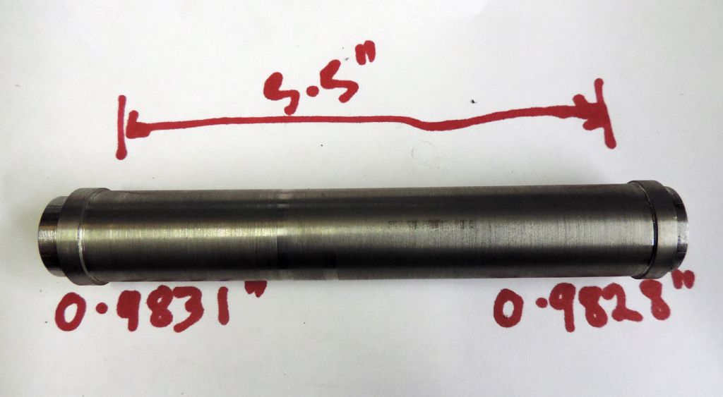
                                        test bar.jpg

                                        Here's one I made earlier…

                                        Neil

                                        NB further tests made with DTI, no need to cut it again.

                                        Edited By Neil Wyatt on 04/06/2021 21:01:59

                                        #548351
                                        Robin
                                        Participant
                                          @robin
                                          Posted by Neil Wyatt on 04/06/2021 21:01:00:

                                          Here's one I made earlier…

                                          Proof of my new notion that all the best lathes are out by 0.0003"

                                          Grumpy people are probably a sign of 0.0004" or greater. We should pity them wink

                                          #548633
                                          John Reese
                                          Participant
                                            @johnreese12848

                                            Pete Rimmer and Hopper are right on the mark. I suggest making the test cuts with sharp HSS to minimize part deflection due to tool pressure. For aligning the headstock to the bed suggest you look for jacking bolts on the headstock. My Clausing Metosa had jacking bolts on the outboard side of the heastock. My Nardini has the jack bolts directly below the chuck.

                                            #548634
                                            John Reese
                                            Participant
                                              @johnreese12848

                                              There is absolutely no need t purchase a test bar. They come from China or India and are of unknown accuracy. The way you turned the test bar in the chuck is the right way to do it.

                                              I feel your pain getting the lathe level. It involves a lot of deep knee bends. If you ever need to re-level the machine find a helper to turn the leveling screws while you read the level.

                                              #548682
                                              Robin
                                              Participant
                                                @robin
                                                Posted by John Reese on 06/06/2021 23:44:21:

                                                Pete Rimmer and Hopper are right on the mark. I suggest making the test cuts with sharp HSS to minimize part deflection due to tool pressure. For aligning the headstock to the bed suggest you look for jacking bolts on the headstock. My Clausing Metosa had jacking bolts on the outboard side of the heastock. My Nardini has the jack bolts directly below the chuck.

                                                Hi John

                                                I measured again, about a zillion times, and I think I got it wrong. Blooming Vernier scales. I think I am 0,0016" out on the diameter.

                                                Best not tell the grown-ups because they get cross.

                                                The bar is still in the chuck and a DTI in the tool post says it is 100% parallel so nothing has moved.

                                                If I drop the front right jack to get 0.0008" error on the DTI would that be cheating?

                                                Robin

                                                #548700
                                                Howard Lewis
                                                Participant
                                                  @howardlewis46836

                                                  If bat first, you don't succeed, try again.

                                                  The EXACT diameter does not matter on your test "bobbin", as long as the reading is the same at both ends..

                                                  I would advocate reworking until you get Zero deflection on the DTI, or whatever level of error is acceptable to you.

                                                  Trying to work to produce an error, may cause confusion.

                                                  Howard

                                                  #548703
                                                  Robin
                                                  Participant
                                                    @robin

                                                    Hi Howard

                                                    The DTI is following exactly the same erroneous path as the tool, so it reads true.

                                                    I reason that I have to make it read wrong before it can cut right.

                                                    Misaligned lathes are about as easy to understand as quantum field theory.

                                                    Robin

                                                    #548709
                                                    Howard Lewis
                                                    Participant
                                                      @howardlewis46836

                                                      I had assumed that you were using the "bobbin" method of checking the alignment, as per Ian Bradley.

                                                      The DTI method is presumably being used with an alignment bar.,

                                                      Not sure that you can mix the two methods, (DTI measuring a bobbin, since it would follow the path taken by the tool).

                                                      But use whichever one provides the required end result of a twist free bed.

                                                      Howard

                                                    Viewing 25 posts - 51 through 75 (of 77 total)
                                                    • Please log in to reply to this topic. Registering is free and easy using the links on the menu at the top of this page.

                                                    Advert

                                                    Latest Replies

                                                    Home Forums General Questions Topics

                                                    Viewing 25 topics - 1 through 25 (of 25 total)
                                                    Viewing 25 topics - 1 through 25 (of 25 total)

                                                    View full reply list.

                                                    Advert

                                                    Newsletter Sign-up