Lathe line boring

Advert

Lathe line boring

Home Forums Workshop Tools and Tooling Lathe line boring

Viewing 16 posts - 1 through 16 (of 16 total)
  • Author
    Posts
  • #288404
    Nick_G
    Participant
      @nick_g

      .

      I need to do some line boring on a lathe. I have never done this before but have seen a couple of videos of it being done.

      First thing I need to do is make a plate that will fix to my lathe cross slide that I can then hold the work down onto.It's one of the shortfalls for model engineers of the Boxford series I have is that it does not have T slots etc. There are however several places I can fix a plate to if I remove the topslide assembly. This is the easy bit that should fall into my existing skill set.

      What bar do I need. EN8, 16, 24. or will EN3 be OK if load stress is lower with this method.?

      The bores to be cut are 40 plus dia mm over nearly 200mm in length. So I realise the bar will have to be at least twice that length. They are both into cast iron. One is for a cylinder liner which ATM is in solid bar so I will have to blitz a hole of at least some diameter thorough it to start with and the other is this casting. :-

      So I could do with some general advice on bar diameter, cutting angles etc, ect, please. smiley

      I would imagine that the work holding and the set up like many machining operations is the crucial bit.

      But hey.! … That Jason B bloke seems to manage it on a regular basis OK. So how difficult can it really be.? surprise winkwink devil

      Cheers, Nick smiley

      Advert
      #18445
      Nick_G
      Participant
        @nick_g
        #288428
        Tim Stevens
        Participant
          @timstevens64731

          Can I suggest that the material for the boring bar is not critical, unless you are in a rush. If the bar is as big as you can readily use (and obtain), and as short as you need, any lack in strength can be accommodated by taking small cuts, especially as you get towards the finished size.

          What matters about a bar for this sort of job is the springiness – how much the bar will deflect as it is pushed to one side (temporarily) by the work it is doing. This depends on the 'Young's Modulus of the material, which varies very little through the range of steels. A stronger bar – high carbon instead of mild steel, for example – will take more force before it takes a permanent set (and fails to spring back to the original size), but you are not likely to be creating anywhere near such a loading.

          Unless I have completely misunderstood your question, and if I have I'm sure someone will put me right.

          Regards, Tim

          #288434
          KWIL
          Participant
            @kwil

            As the OP wishes to line bore the casting, his biggest problem lies in the setting up.

            The "as cast hole" is quite large so the between centres boring bar can be equally large in diameter, material should not be a problem at that size..

            #288440
            Neil Wyatt
            Moderator
              @neilwyatt

              The cuts don't get bigger as the diameter increases so at a point where deflection becomes negligible (about 3/4" to 1" I would guess) extra diameter for the boring bar is just a waste of material.

              Neil

              #288441
              stevetee
              Participant
                @stevetee

                I'm sure I am pointing out something that will be obvious to you, but you should plan to machine the base first of all to a finished dimension working from the nominal centreline of the bore. Then you have a nice flat face to clamp the workpiece down for other machining. That face  will then be the datum face for all the other dimensions. Normally there is plenty of meat on castings so it should not be too much of a problem. .

                Edited By stevetee on 12/03/2017 13:57:39

                Edited By stevetee on 12/03/2017 13:58:39

                #288447
                Clive Foster
                Participant
                  @clivefoster55965

                  Tool size is an issue with between centres boring bar stiffness as the cut out for the tool clearly reduces stiffness. I've seen 10:1 plus tool diameter (assuming round tooling) quoted as a reasonable length diameter ratio for essentially zero deflection on our sizes of job. So 1 1/4 " bar for 5" deep hole with 1/4" tooling. As Neil says stiffness goes up rapidly with diameter so the formula fails when you get to big stuff like yours. Stiff enough is stiff enough 1 1/4 bar should be plenty for you. I've seen designs where the cutter mounting area has been enlarged to help ensure secure mounting and clamping of the cutter with the main bar being smaller to give a bit more room for measurement.

                  Cutter at an angle as per Geo. H Thomas makes setting easier and provides more support for the tool. If I ever need a big one I shall use thick wall tubing for the main bar with a lump fixed in the centre to hold the tool. Got a couple of foot of nice 1" diameter by 1/4" wall steel just right for the job in stock.

                  I have a long 1" diameter single ended boring bar and do need to start thinking about deflection beyond around 3 or 4 inches. Tool tip shape makes a big difference. Too much tip radius will increase push out forces considerably. Boring bar supported from both ends is effectively twice as stiff.

                  With a hole that size there is room to run the tailstock quill out a bit into the bore. So the bar can be less than double the bore length making the system stiffer. Puts cutter closer to the support too which also helps. Disadvantage of running the tailstock quill into the bore is less space to get the measuring gear in.

                  clive.

                  #288455
                  Willliam Powell
                  Participant
                    @willliampowell36769

                    All good thoughts above.

                    A different tactic might be to use a piece of DOM tubing, say 1" OD with a half inch bore. Counterdrill the ends and install threaded plugs back about 3/4 inch. Pack the bore with lead shot.. This allows you to use large centered ends whic place the bar further up on your live center, reducing leverage on it. The cutter head is separate, and retains the high speed steel square in a slot milled in the face. This allows you to get the top surface of the bit at the center line. A little shallow hole in the bar, and a dog point set screw hold the cutter head in place.

                    You don't lose much stiffness in using the DOM tube over solid, and the lead shot makes the bar very dead to vibration. That's how I made my last one.

                    #288457
                    JasonB
                    Moderator
                      @jasonb

                      I'd go for a bit of 35mm bar as you are more likely to pick that up from a local stockholder than imperial sizes. At 35mm it will fit up your spindle so easy to face off and pop a ctr drill hole in the end. I could also be used as a single point tool in the same way by drilling th eend for a toolbit, I have found this useful on several occasions to open up holes enough to get a between ctrs bar down.

                      There does come a point where a larger dia bar is worth having as just like normal turning if you have a lot of toolbit sticking out the bar it is more likely to chatter than the same size toolbit just protruding from a larger dia bar.

                      Personally I tend to use a square tool bit either 3/16 or 1/4 as the flat ensures it goes back in the same position if you take it out to sharpen. . Remember to drill cross hole just off centre of bar so the cutting edge of tool is radial unles syou want to grind half of it away.M5 or M6 grub screw to lock it into place.

                      I find it easier to drive one end in the 3-jaw rather than having teh bar between centres and easier to arrange than fitting a big dog or drive stud and any excess length can again go up teh spindle to keep length at a minimum.

                      I think your plan of attack will be 1. bore the hopper as you have less control of the diameters. 2, turn OD of liner to suit finished bores of hopper. 3. open out liner to about 38mm. 4. Press/Loctite liner into place, 5. bore liner to finished size and face off end of hopper/liner at the same setting. It would be nice to do it all without removing the hopper but I think trying to get the hopper to fit a previously machined liner OD will be harder.

                      J


                      PS expect pics of finished item by Monday PM


                      Edited By JasonB on 12/03/2017 15:49:42

                      #288459
                      Tim Stevens
                      Participant
                        @timstevens64731

                        DOM = Drawn Over Mandrel?

                        Tim

                        #288461
                        Speedy Builder5
                        Participant
                          @speedybuilder5

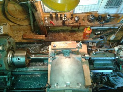
                          Here is one I did earlier. As you can see, the cross slide of the Boxford has been enlarged using a sheet of plywood bolted and temporarily glued to it to stop it moving about. in the photo, i was drilling a hole through the aluminium casting prior to line boring between centres./the job was far a full sized Bugatti type 32 clutch housing

                          clutchhousing2.jpg

                          #288516
                          Nick_G
                          Participant
                            @nick_g

                            .

                            Many thanks guys smiley

                            Good information there.

                            Nick

                            #288521
                            HOWARDT
                            Participant
                              @howardt

                              Re your original question on material. Whilst for the model engineer I would use anything steel for the bar in the manufacturing industry heavy metal is used, basically a tungsten based metal of high density hence stiffness. Cutting edges would be mounted in micro bore units, which allow micro setting of cutting diameter.

                              #288534
                              John P
                              Participant
                                @johnp77052

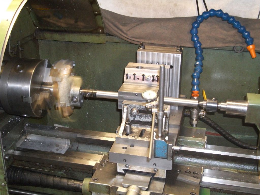
                                I use a method seen in MEW issue 168 page 56 by Ted Barclay in
                                which an amalgamation of a between centres boring bar and boring
                                head produces a very accurate result .
                                You can just see the Dore boring head revolving the boring bar articulates
                                when the cut is applied as the toolbit is halfway between the boring head
                                and the tailstock the graduations on the boring head dial are halved.

                                The deflection of the boring bar should not be much of problem ,when
                                boring like this on the crosslide you should ensure that the fixing of the
                                work to the crosslide is rigid enough and the clearance between the
                                saddle and the lathe bed is minimal.As can be seen in the photo the
                                work piece here forms a bridge between between the two supporting
                                parts ,the crosslide is locked during cutting.The clock gauge is left in place
                                during cutting to detect any movement.

                                John

                                boring bar.jpg

                                #288570
                                Nick_G
                                Participant
                                  @nick_g

                                  .

                                  Hi John,

                                  That's a good idea. Makes the cuts very controlable I would think.

                                  Cheers, Nick

                                  #288584
                                  Nigel McBurney 1
                                  Participant
                                    @nigelmcburney1

                                    I usually get involved with full size stationary engines and some hot air engines,there is an old saying that better results are achieved with the work rotating and the tool stationary,and I prefer where feasible to bore cylinders off the faceplate and liners using chuck and or steady,I did line bore a 5 inch dia Blackstone cylinder of the saddle of an older Colchester roundhead master,which does have some T slots in the saddle.The boring bar was about 23/4 dia and about 3 ft long,it was a worn slide bar from a large cmc mill, Cutter was a small brazed on carbide tip,I would have preferred HSS tools but tool wear comes into play,the between centres boring bar produces a constant diameter which is a big advantage but the bore can end up tapered due to tool wear.With the between centres set up lack of rigidity both of work holding and the long bar can cause vibration and tool chatter and a poor finish,to reduce chatter it is a case of experimenting with tool tip radius,too big a rad and the tool will chatter,too small and it will a poor finish will be the result ,also keeping the cutting surface speed down will improve surface finish,the brazed on carbide tip tool allows the tool to be ground and honed to a sharp edge,unlike replaceable tips.Always line bore first and then make the mating parts to suit,its easier to turn accurately than to line bore also a liner is cheaper than a cylinder casting if a disaster occurs ,always hone cylinder bores they do need a good finish,if the surface finish is poor the rings will make a scraping noise as they run up and down the bore. When working on these old engines I often wonder how long it took to bore a cylinder from a rough casting when all they had was carbon steel tooling,how many times did they have to take their tools to the grinder and reset ?

                                  Viewing 16 posts - 1 through 16 (of 16 total)
                                  • Please log in to reply to this topic. Registering is free and easy using the links on the menu at the top of this page.

                                  Advert

                                  Latest Replies

                                  Viewing 25 topics - 1 through 25 (of 25 total)
                                  Viewing 25 topics - 1 through 25 (of 25 total)

                                  View full reply list.

                                  Advert

                                  Newsletter Sign-up