It no worky !!

It no worky !!

Home Forums Beginners questions It no worky !!

Viewing 21 posts - 1 through 21 (of 21 total)
  • Author
    Posts
  • #327276
    Nick Ogden
    Participant
      @nickogden47955

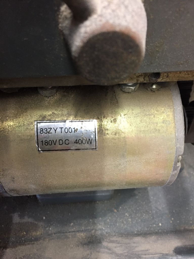
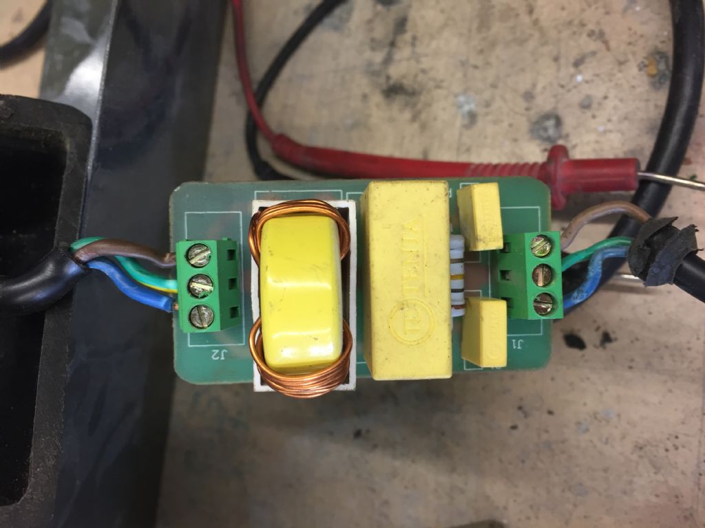
      Hi all Numpty here. The lathe was working fine but now fails to power up. I’m assuming that with a 240volt ac input on J2 should there be 180 volt dc at J1 ? There is no out out at J1. If so I assume that the circuit board is dead. Are they available?

      Thanks in advance

      Numpty of Essex

      2017-11-12 12.10.21.jpg2017-11-11 13.31.50.jpg2017-11-11 13.31.43.jpg2017-05-07 12.50.13.jpg

      #8970
      Nick Ogden
      Participant
        @nickogden47955

        Help a Numpty

        #327290
        Bazyle
        Participant
          @bazyle

          Did you check the interlocks?

          #327296
          Andy Carruthers
          Participant
            @andycarruthers33275

            I am guessing the first donut is an inductor…? large yellow block is a bridge rectifier and the smaller yellow blocks are smoothing capacitors

            Do you have any output from the inductor to the bridge rectifier?

            #327300
            Anonymous

              It's more likely the small board shown is AC in and AC out, it's for RFI filtering.

              The yellow toroid with copper wire on the left is a common mode choke. The large yellow block is the X capacitor (across L and N) and the two smaller yellow blocks are Y capacitors (L to PE and N to PE).

              Andrew

              #327301
              Nick Ogden
              Participant
                @nickogden47955

                Thanks for the replies. I am getting no voltage whether AC or DC on the output of the board on connector J1.

                Am I expecting to see AC as an output then on J1. ?

                As you can probably gather, electronics are not my strong point.

                Nick

                #327304
                Michael Gilligan
                Participant
                  @michaelgilligan61133
                  Posted by Andrew Johnston on 15/11/2017 13:51:53:

                  It's more likely the small board shown is AC in and AC out, it's for RFI filtering.

                  .

                  Andrew's judgement is, I sincerely hope, strongly supported by the fact that J1 and J2 are both wired with U.K. colour-coded Mains cable [flex].

                  MichaelG.

                  .

                  The circuit should therefore look something like the first technical diagram on this page:

                  http://www.reo.co.uk/product/156

                  I do wonder if the board is connected the wrong way round, though.

                  [quote] 

                  I am getting no voltage whether AC or DC on the output of the board on connector J1. 

                  [/quote]

                  Common practice would be for the connection labelled J1 to be the line input.

                  Edited By Michael Gilligan on 15/11/2017 14:21:39

                  #327308
                  Neil Wyatt
                  Moderator
                    @neilwyatt

                    It's a filter board, mains in mains out.

                    If you try and read DC on the output you will get (near) zero whatever range you use.

                    #327309
                    Anonymous

                      Is there an AC voltage across the outer two terminals on J2? The wiring doesn't look to be in the best shape, especially the live wire into J2.

                      It would be useful to see the tracking underneath the PCB. Normally you'd expect to have the X capacitor followed by the common mode choke and finally the Y capacitors, which isn't reflected by the physical position of the components.

                      Andrew

                      #327310
                      Nick Ogden
                      Participant
                        @nickogden47955

                        Thanks for all your help. I will double check everything tonight…at least I know I'm searching for AC now.

                        Every day is a learning daylaugh

                        #327339
                        Les Jones 1
                        Participant
                          @lesjones1

                          WITH THE LATHE NOT PLUGGED IN meaure the resistance between the top terminal of J2 and the top terminal of J1 report the reading. Meaure the resistance between the bottom terminal of J2 and the bottom terminal of J1 report the reading. I would expect these reading to be less tahn 2 ohms. It does not look like the filter choke has been damaged by excessive current so I suspect there could be a bad solder joint on the filter board or blown track. Post a picture of the etch side of the filter board.

                          Les.

                          #327351
                          HughE
                          Participant
                            @hughe

                            Les's idea is the safest as there will be no power applied. Common fault is a poor solder joint. It can be caused by either a poor connection getting hot causing the solder to melt the other is that the insulation on the choke wires was not removed sufficiently causing a weak joint. Due to the way the toroid is mounted any vibration would cause the joint to fracture, add a dab of glue from a glue gun to support it.

                            Edited By HughE on 15/11/2017 17:24:11

                            #327354
                            Grizzly bear
                            Participant
                              @grizzlybear

                              To prove the input/ RF filter board, remove mains in & mains out, join them together, like for like. Power up, Go = board duff. No Go = fault elsewhere.

                              Good luck, Bear..

                              #327364
                              Neil Wyatt
                              Moderator
                                @neilwyatt

                                If Nick was looking for 180V DC he won't have found it. The board is probably OK.

                                It's likely the fault is further down the chain.

                                #327367
                                Grizzly bear
                                Participant
                                  @grizzlybear

                                  "If Nick was looking for 180V DC he won't have found it. The board is probably OK.

                                  It's likely the fault is further down the chain."

                                  Agreed, Neil, I just wanted to move on.

                                  Bear..

                                  #327370
                                  Alan Vos
                                  Participant
                                    @alanvos39612

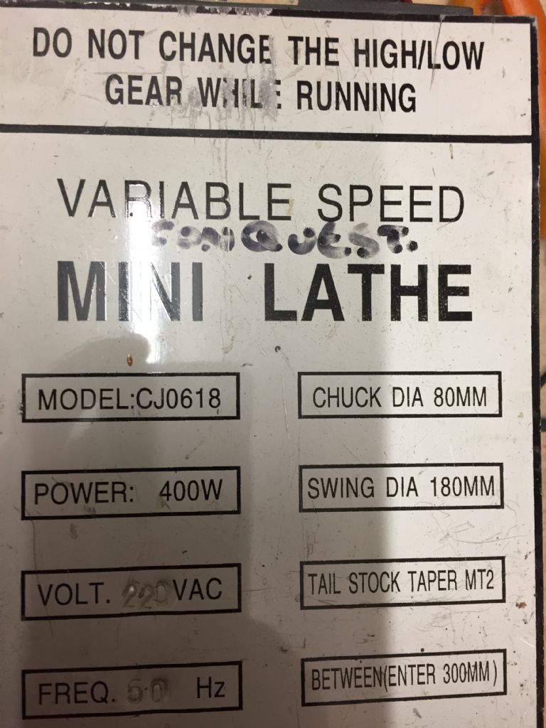
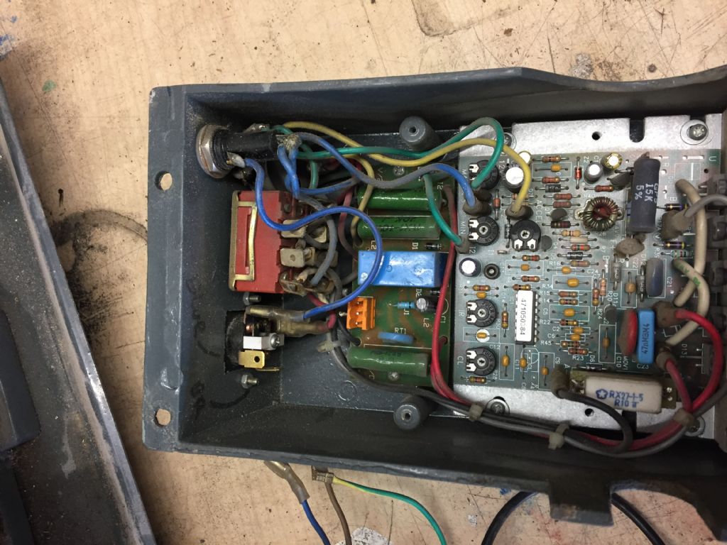
                                    As it says 'CONQUEST' I will assume this is from Chester. I have one of those. It stopped working. All it could do was blow fuses – the glass fuse on the control box, never the plug fuse. How are the fuses? Is there any AC votage on the input to the PCB?

                                    In my case it was due to water getting into the control box. The power semiconductors are at the botton of the control box. Their legs had got wet. Replaced all five. Back in business. Fiddly though.

                                    Are control boards available? Mine was from KB Electronics, either a KBIC-240 or KBLC-240, I forget. Those are available for £90-100. Basic DC speed controllers seem to have reached 'good enough' some years ago.

                                    #327375
                                    Anonymous

                                      It does seem unlikely that the fault is with this board, but you never know. I've had problems caused by poor quality copies of UK/US connectors, so you can't rule anything out.

                                      While the OP says electronics isn't a strong point I do wonder about responders who don't seem to be able to read. disgust The OP clearly states he is getting no output, AC or DC.

                                      Andrew

                                      #327379
                                      Michael Gilligan
                                      Participant
                                        @michaelgilligan61133

                                        No guarantee expressed or implied !!

                                        I've just found this: **LINK**

                                        https://goo.gl/images/wengtS

                                        The parent page is a MadModder thread: **LINK**

                                        http://madmodder.net/index.php?topic=4962.0

                                        [which is sadly full of inaccessible images]

                                        MichaelG.

                                        #327493
                                        Nick Ogden
                                        Participant
                                          @nickogden47955

                                          Thanks for all your help. It would seem that there is no continuity across the board. Can I simply buy an in-line emi filter module as a replacement £4.96 from our favourite online auction site 112201070823 Thanks again Nick

                                          #327500
                                          John Haine
                                          Participant
                                            @johnhaine32865

                                            That looks ok. Slightly concerning that there's no current rating given. For the purposes of test, you could try replacing the current filter with a piece of 3-way choc block (terminal strip), corresponding colour to colour. If its the filter then everything should work OK. But some noise will be getting back into the mains – whether that worries you is a matter for your conscience! By the way the replacement you mentioned only has earth at one end, the input so you'll finish up with a spare earth wire. That should be connected to the earth at the input I guess, otherwise your lathe will not have an earth connection.

                                            #327503
                                            Nick Ogden
                                            Participant
                                              @nickogden47955

                                              Yes I have connected straight through bypassing the board and all is working fine. Yes I noticed the earth connection as you state. Thanks again I will order one This site has been a great help Nick

                                            Viewing 21 posts - 1 through 21 (of 21 total)
                                            • Please log in to reply to this topic. Registering is free and easy using the links on the menu at the top of this page.

                                            Latest Replies

                                            Home Forums Beginners questions Topics

                                            Viewing 25 topics - 1 through 25 (of 25 total)
                                            Viewing 25 topics - 1 through 25 (of 25 total)

                                            View full reply list.