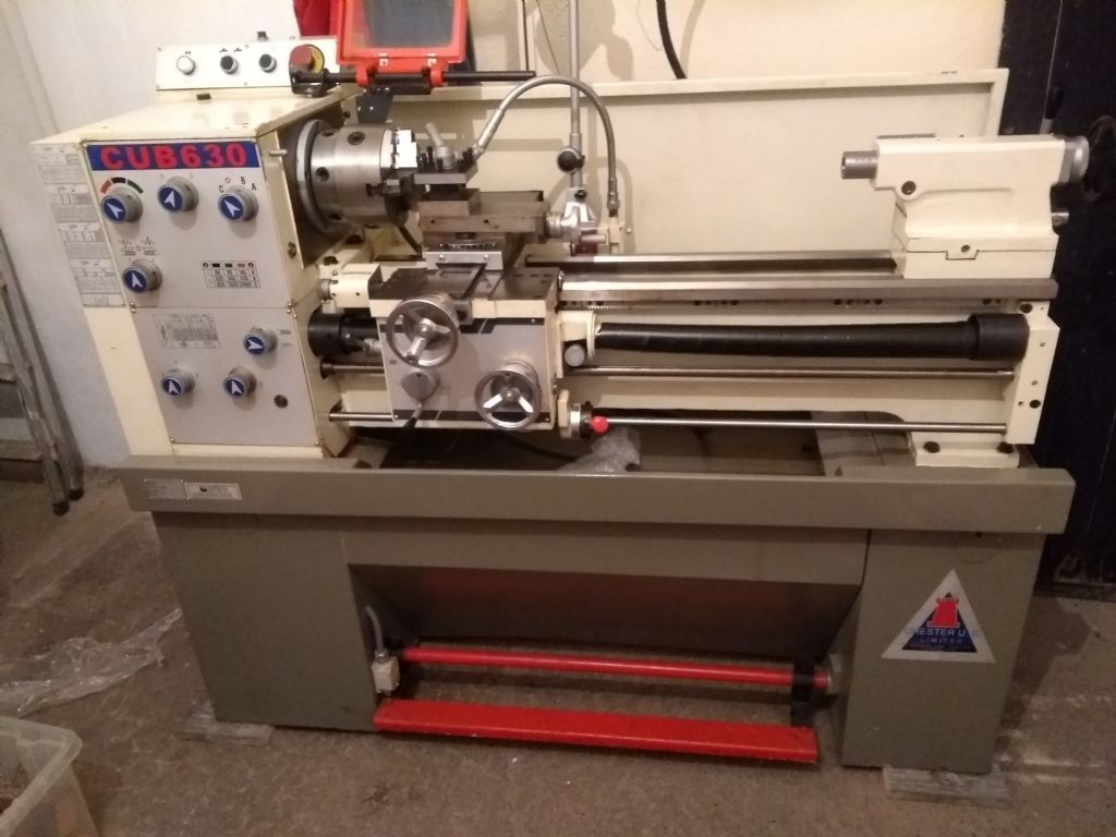
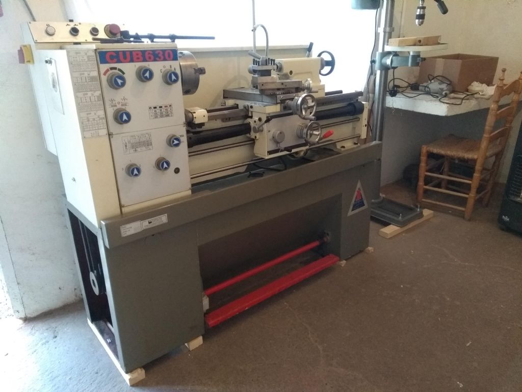
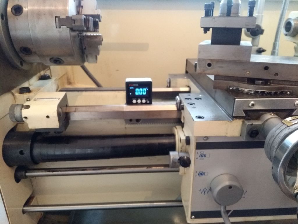
Install & commission of a Chester Cub 630 (Warco GH750)

Advert

Install & commission of a Chester Cub 630 (Warco GH750)

Home Forums Manual machine tools Install & commission of a Chester Cub 630 (Warco GH750)

Viewing 25 posts - 26 through 50 (of 69 total)
  • Author
    Posts
  • #549357
    Clive Foster
    Participant
      @clivefoster55965

      Concerning oils the ISO number is the viscosity of the base stock, low numbers means it flows easily and is thin, high numbers flows less easily and is thick.

      Variations between recommended applications for oils of the same nominal viscosity are due to the additive package with is tuned to work best at that job. For example slideway oils have additives to help them stick to surfaces so, for example, the oil doesn't just run off vertical slides and others to stop it oxidising when sitting around in thin layers for long periods. Motor oils and similar tend to turn into a varnish like coating over the eyars. Especially older type. Slideway oils made specifically for machine tool use are tolerant of cutting oils, suds et al and the water used to dilute it.

      Hydraulic oils generally have anti-foam additives so it doesn't become aerated inside pumps, anti wear additives so sliding cylindeers don't wear out too fast and be formulated so the seals can easily scrape excess oil off.

      Vacuum oils are tuned to minimise any out gassing of components under low pressure. Compressor oils, made for reciprocating compressors, can stand the relatively high loadings on big and little end bearings. Also made to minimise leakage past piston rings. Oils for rotary compressors such as screw and hydrovane types tend to be a bit exotic with prices to match.

      Consensus seems to be that for any home workshop compatible lathe an ISO 32 hydraulic oil with anti wear additives is good for bearings, gear boxes and oil nipples on the machine et al. ISO 68 dual rated slideway / bearing oil for the bed, drop gear train and possibly apron. Castro technical department suggested that I use Hyspin AWS32 and Magna DB 68 many years ago. Not seen any reason to deviate despite several machine changes. The Magna makes a great general purpose oil can oil for "honey doo" and similar general lubrication jobs as it stays in place for long periods. Magna strings impressively when applied to open gears and quickly spreads over the teeth but doesn't drip unless you overdo things. Equivalents can be got from most oil makers.

      Proper slideway only oils are heavy duty beasts and rather too sticky for our machines.

      Clive

      Advert
      #549365
      Clive Foster
      Participant
        @clivefoster55965

        Levelling is a vastly over discussed subject.

        For folk like us its most relevant to the lighter range of machines, Myford, Boxford, Southbend and smaller, where careless bolting onto a strong but un flat bench can distort the bed.

        Similar considerations apply to larger machines with the old fashioned pedestal at the headstock end, legs at the tailstock end and unsupported bed between. Maybe with a chip tray bolted in place. If the floor is insufficiently flat you end up with it sat on three points with one leg, almost invariably at the tailstock end, hanging in the air. Packing the hanging leg to equalise the loads side to side on the feet is sufficient to take out the stress on the bed. The machine mass won't bend a bed that big. Users choice how level you want it.

        Lathes solidly bolted to sturdy cabinets, whether sheet and angle frame like yours, or fully cast boxes like my Smart & Brown 1024, are essentially unbendable and untwistable by any forces folks like us can apply. So assuming the maker hasn't had a Friday afternoon moment and twisted things by making the mounting points out of parallel the machine will be quite happy so long as the mounting points are shimmed to equalise loads as mentioned above. Being close to level is nice on a lathe but frankly carpenters level or wixley type digital is good enough.

        Taking the time to get a mill table really level is worth it as being properly level makes many set ups easier.

        I've always found it quite sufficient to use a thin metal sheet, preferably shim, between two lubricated plates in conjunction with a screw jack to judge loads on the mounting points. Basically settle the machine down on the plate stack and judge how much of a turn on the jackscrew it takes to lift one or the other corner enough so the ship plate is stiff to move. I reckon around 1/10 turn between fully loaded and slides when testing alternately is close enough. Change the stack for proper solid shim once you have the adjustments sorted.

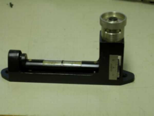
        Did both my P&W model B, pedestal-leg type, and S&B 1024, cast box underneath, that way. Both within a few seconds of level when checked afterwards with my favourite WW 2 gunners clinometer.

        clinometer 1.jpg

        30 seconds of arc per division. Small so you can turn it end for end to test. Calibrated tilt adjustment so you can work your way down.

        Super precision levels are a pain to use because the bubble is slow to settle and mostly parks itself at one end so little help until really close. Carpenters and wixley style digitals are, objectively insufficiently accurate if you really want level.

        But with a lathe so long as the bed is unstressed out of level, within reason, matters little.

        Clive

        Edited By Clive Foster on 11/06/2021 18:37:27

        #549455
        Howard Lewis
        Participant
          @howardlewis46836

          Unless you are planning to use flood coolant, having the lathe EXACTLY level is not important.

          If using flood coolant the lathe should be levelled, obviously, so that coolant runs towards the return to tank.

          More important is that the bed is free from twist. If twisted, the lathe is liable to cut a taper.

          You can use a sensitive level to show how much twist is present. This will show you directly in which direct to adjust the tailstock end of the bed.

          Or you can use the method advocated by Myford, and by Ian Bradley in his book, "The Amateur's Workshop"

          Pages 27 and 28 apply.

          Basically, you adjust / shim at the Tailstock end, when the lathe is firmly bolted down..

          If using the "bobbin" method, is used, cuts should be light, only 0.002" (0.050 mm).

          The tool must be on the centre height of the lathe for any cutting. It will not cut properly, unless it is.

          The basic material (Usually mild steel ) should be 1" (25 mm ) diameter, so that it is stiff and unlikely to deflect under cutting forces. Also, for this reason, the cuts should be light,

          Measure the diameters at the Headstock and outer ends of the bobbin.

          Only a little more than 6" (150 mm ) should protrude from the chuck.

          If the bobbin is larger at the outer, unsupported end, place shims, or adjust upwards, under the FRONT foot at the Tailstock end.

          If the outer end is smaller, insert shim, or adjust upwards, the REAR foot.

          Having made the adjustment, take another light cut and remeasure the diameters of the ends of the bobbin.

          Repeat the shim/adjust and light cut procedure until both ends are the same diameter. The bed is then without twist.

          HTH

          Howard

          #549604
          John P
          Participant
            @johnp77052

            Hi Calum,
            There is some useful viewing on the video of this page of
            a similar machine to yours.

            https://sites.google.com/site/lookatwhativegot/lathe-for-sale?tmpl=%2Fsystem%2Fapp%2Ftemplates%2Fprint%2F&showPrintDialog=1

            I have a Warco GH1000 which is from the the same series of lathes.
            I changed the oil in the headstock ,gearbox and apron soon after
            i got it ,i used ep 80 gear oil from Halfords in the 20 years that i
            have had the machine i runs as quiet now as when new both in
            forwards and reverse.

            I use neat cutting oil flood coolant (Excelcut 401) which is fortunate
            as the coolant seems to find its way into the apron gearbox and fills
            it to the top, bad if you wish to use suds coolant very probably it will
            displace the oil in the box.
            The occasional squirt of 68 grade slideway oil just from an oilcan
            with bent spout is enough ,using neat cutting oil the slideways
            are always covered in oil ,not the best oil for lubrication but there
            is so much of it there the slideways are still as new.

            Having two level pads for each end to stand on would be a good
            start these machines have three bolting points at each end ,
            in the centre at each end of the machine and each side on the
            inner sides of the plinth ,providing they are level with each other
            it will be a simple job to pack to get the machine cutting parallel.

            I used the same method as described by Howard in the previous
            posting ,it works.

            The coolant tray on these machines are quite deep you may find
            on the 630 machine it will have a slide out coolant tray which is
            a useful thing.
            When Warco delivered this machine it was on two small pallets
            bolted down on the fixing points at each end of the machine
            a long pallet truck picked up the machine , onto the tail lift then
            around a much more tortuous route than you have over some
            crazy paving pathway and straight into the workshop .
            If you have a pallet truck available you may be able to do a similar
            thing ,even a small one may do as your machine is 10 inches shorter
            than my GH 1000.

            John

            #551210
            Calum
            Participant
              @calumgalleitch87969

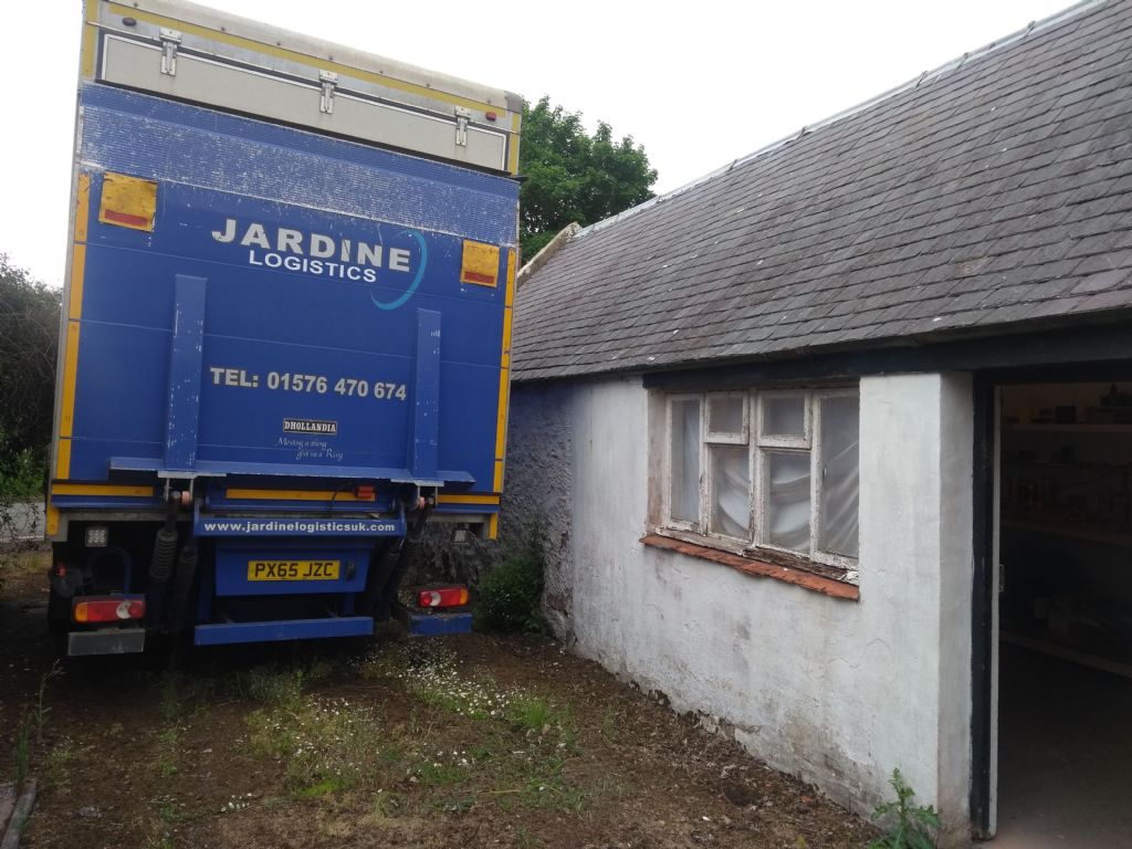
              Well, after much twiddling of thumbs, last Thursday I got a call asking when I would like to take delivery: well, no point owning a lathe sitting several hundred miles away, so on Monday I got another call from a jovial delivery driver intimating he was fifteen minutes away and would I put the kettle on. Gladly.

              He took one look at the narrow space between my workshop and the garden wall: "aye, nae bother", and proceeded to reverse a 12-tonne truck in as if it were a Mini into the Bay of Biscay.

              He drank his tea, apologised for not having anything to lift the lathe off the pallet "or I'd get that in there nae bother", jumped in his truck and zoomed off, leaving this:

              img_20210621_134036861.jpg

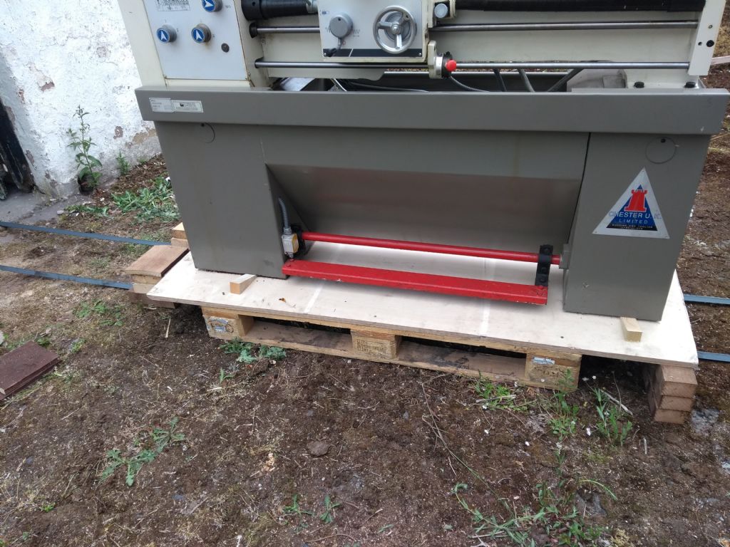
              Gulp. I finished my tea and set to work. I hadn't planned on that big ol' sheet of ply being in the way of getting the cabinet jacked up, so plan B was hastily developed.

              img_20210621_150007556.jpg

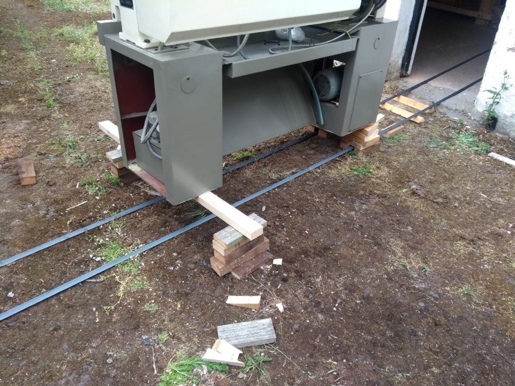
              I laid down the rails for the machine to slide on (ominous foreshadowing alert), plaved blocks for the headstock end to repose on, and began jacking the machine up. I had made a lot of wedges from goodness knows what bit of 6×2 construction lumber, and this was the first thing I learnt: it's worth making wedges out of a decent hardwood, and making them a decent size. Wedges twice the size would have made life so much easier.

              img_20210621_151236855.jpg

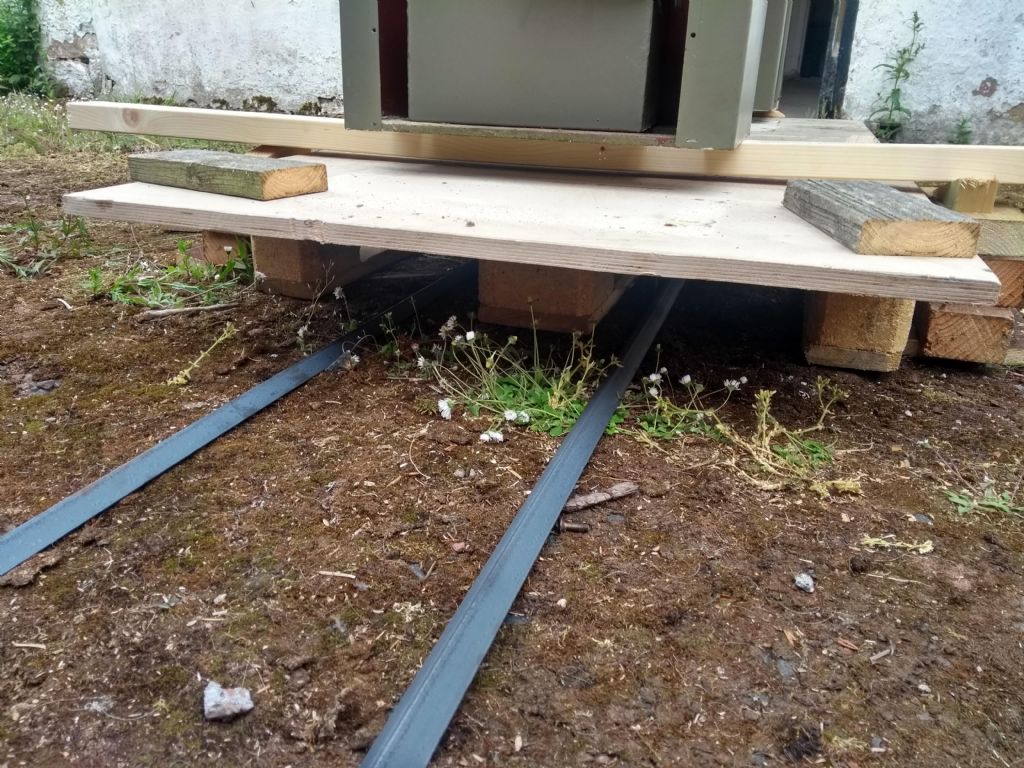
              The machine rolled forward using a bit of random aluminium tubing. Now the tailstock end was a problem: how to support it so I could get the pallet out? After some guesstimation, I was fairly confident a bit of C16 timber would take the weight. It didn't look so scary like this:

              img_20210621_155113482_hdr.jpg

              But after carefully dragging the pallet out and seeing this:

              img_20210621_155418506.jpg

              Well, to my simple mind, lathes should be on the ground, not levitating up in the air. (By the way, Clive mention a removable suds tray. It can indeed be removed, but only from the back. It was only just before I finally parked it for good I realised it had been put back in the wrong way round, explaining why the drain hose is attempting to cool the motor rather than draining to the suds pump visible on the left).

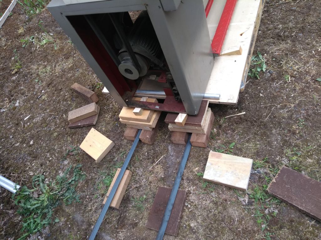
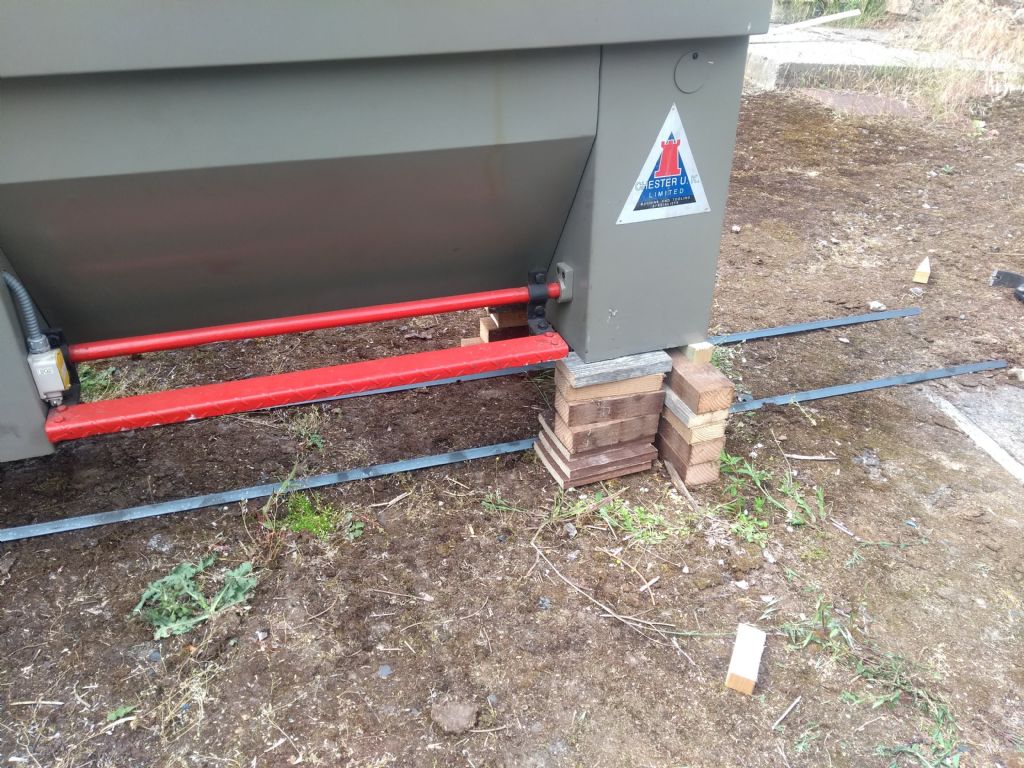
              Getting it back down was precarious. I should have been a lot more careful about blocking it up, as you can see here:

              img_20210621_160804698.jpg

              As we worked down, that pile of blocks next to the footbrake ended up getting pushed over as the lathe tried to move sideways from the repeated lifting and setting down. About half way down, the pile gave way – fortunately it moved all of a centimetre before landing on my pry-bar blocks. It wasn't until I saw this photo in retrospect that I realised quite how careless I was being with the height I had raised the lathe. Incidentally, another thing I learnt doing this was that saving a tenner on a pry bar seems like a false economy when halfway through a move you reflect that if it breaks, it has 500kg of lathe on one end and a bag of flesh (mine) on the other. That said, the adjustable pry-bar was really helpful, and I'm glad I didn't just have a plain one. FInally, however, I had it down on the rails:

              img_20210621_191421070.jpg

              At this point, I had somewhat optimistically expected that the lathe might glide upon the rails as a swan upon the lake, perhaps with me providing a gentle hand to steer it. Nope. I put my shoulder down and pushed. Nope. I roped in my mother, more in hope than expectation given that she weighs about the same as a dormouse and could do with two new hips and a lung transplant. Our combined efforts moved it a good half inch before we called a halt. Plans C, D, E, and F were quickly drawn up and discarded before we returned to the wisdom of the ancients, specifically Archimedes. If one inserts a pry-bar between the base and the ground, and then lifts up, the lathe moves forwards 2-3cm each time. As a form of locomotion it leaves much to be desired, but a few hours later, it was inside the workshop, the door could be locked, and I retreated inside for a most necessary libation.

              img_20210621_233810080.jpg

              #551211
              Calum
              Participant
                @calumgalleitch87969

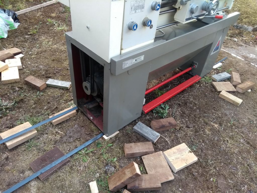
                The next morning's work was rather easier: I neglected to take pictures, but I had put together some dollies that I was confident could carry the weight safely, and while blocking it up, moving it, and dropping it down again was frankly a pest – it's been a while since I've had to work so hard! – the process was much less of a struggle. For now it's sitting on some bits of timber which have got it surprisingly close to level:

                img_20210622_175721092.jpg

                img_20210622_175740184.jpg

                #551218
                Pete.
                Participant
                  @pete-2

                  That looks like a lot of hard work, I bet you're in no rush to repeat that! looks like it's in good condition, a good size too, as soon as you start using it, all that humpin and heavin will be forgotten.

                  What else are you planning on adding to the workshop?

                  #551247
                  ChrisH
                  Participant
                    @chrish

                    Calum – well done getting your lathe into your 'shed', even if you did scare the life out of me with pictures of your lathe up on blocks, esp the blocks in-line longitudinally, I was thinking if I did that with my luck that would soon be over on it's side maybe with me underneath! Are you going to post a pic of it secured and leveled up for us to adnire!

                    Chris

                    #551264
                    Calum
                    Participant
                      @calumgalleitch87969

                      Thanks Chris, yes, it was definitely one of those operations that I would not repeat in that way! I should have done exactly what I had at the headstock end, which was very solid with the blocks straddling the rails and would have been easier and quicker too. As for levelling it, I've got some feet on the way, though the concrete it stands on is more like a hill than a floor, so the bits of timber at the left will probably stay.

                      Pete, I'm happy to say in the immediate future, not much! The first priority will be to get the lathe tooled up – it came with practically no accessories; it has a 3 jaw chuck and key, but not the key for the D1-5 spindle. I'm not sure if it even has a full set of changewheels. No rests, no 4 jaw, no faceplate, no centres, no cutting tools. Even the handle from the tailstock wheel is MIA! Something I will need to produce for what I want to do is a taper attachment.

                      I've got two immediate problems:

                      1. The chuck has been on the spindle for probably fifteen years or more. I need to get a spindle key that fits properly (the chuck key is a bit small), but even so it feels like the cams are seized pretty solid. I've put a bit of welly into all six and none show any interest in moving. I don't want to put any more force on till I get a suitable key.

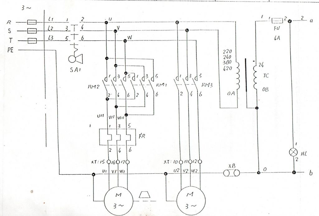
                      2. The electric lead into the machine has four cores, for three phase and earth. But…all three conductors are black, and I can't trace where the incoming conductors go in the electrics panel without undoing screws. Am I risking magic smoke if the machine ends up getting fed the wrong rotation? Or will it just go backwards? I have a very basic schematic of the electrics, which suggests nothing should go bang:

                      screenshot from 2021-06-25 13-28-07.jpg

                      #551274
                      Lathejack
                      Participant
                        @lathejack

                        Well your newly acquired lathe looks like a really good buy. From your photos it appears to have had very little use, does it look like it's ever done any work at all?

                        Anyway, as soon as you can, let's have a vid of it running with the various knobs and levers being twiddled with. Very interested to see how it goes.

                        Edited By Lathejack on 25/06/2021 14:28:05

                        Edited By Lathejack on 25/06/2021 14:30:11

                        #551281
                        Emgee
                        Participant
                          @emgee

                          Calum

                          If connecting a true 3 phase supply you are right to believe if phases not correct it will turn in reverse if fwd selected, no damage should occur.

                          Emgee

                          #551310
                          Calum
                          Participant
                            @calumgalleitch87969

                            The only evidence of use I can find is some bits of swarf in the suds drain plate. Other than that, no, it looks disconcertingly original. I suspect the run time can be measured in minutes; there is some rust spotting and whatnot if you get close up but nothing looks used as such. Next job is to get the electrics all hooked up so we can make it go brrrrr. Thanks Emgee, yes, we're on what used to be a working farm so we've three phase on site, and it turned out a spur already ran within a few metres of the lathe.

                            I mentioned a while back there was a 10" D1-5 4 jaw chuck going on eBay for £150 – last night I noticed it had been knocked down to £120 so I grabbed it. It will be a big old thing but the price of new D1-5 chucks is, well, phew. It'll be a while before I add a 4 jaw self-centring chuck to the setup.

                            #551374
                            Pete.
                            Participant
                              @pete-2

                              Probably a wise decision, it gets expensive starting from scratch, I would recommend the diamond turning tools from eccentric engineering, it was around £170 for the left and right 16mm set with a couple of the 50% cobalt tool bits iirc, but they're virtually free from there on, and give you great finishes.

                              #551418
                              John P
                              Participant
                                @johnp77052

                                Hi Calum,
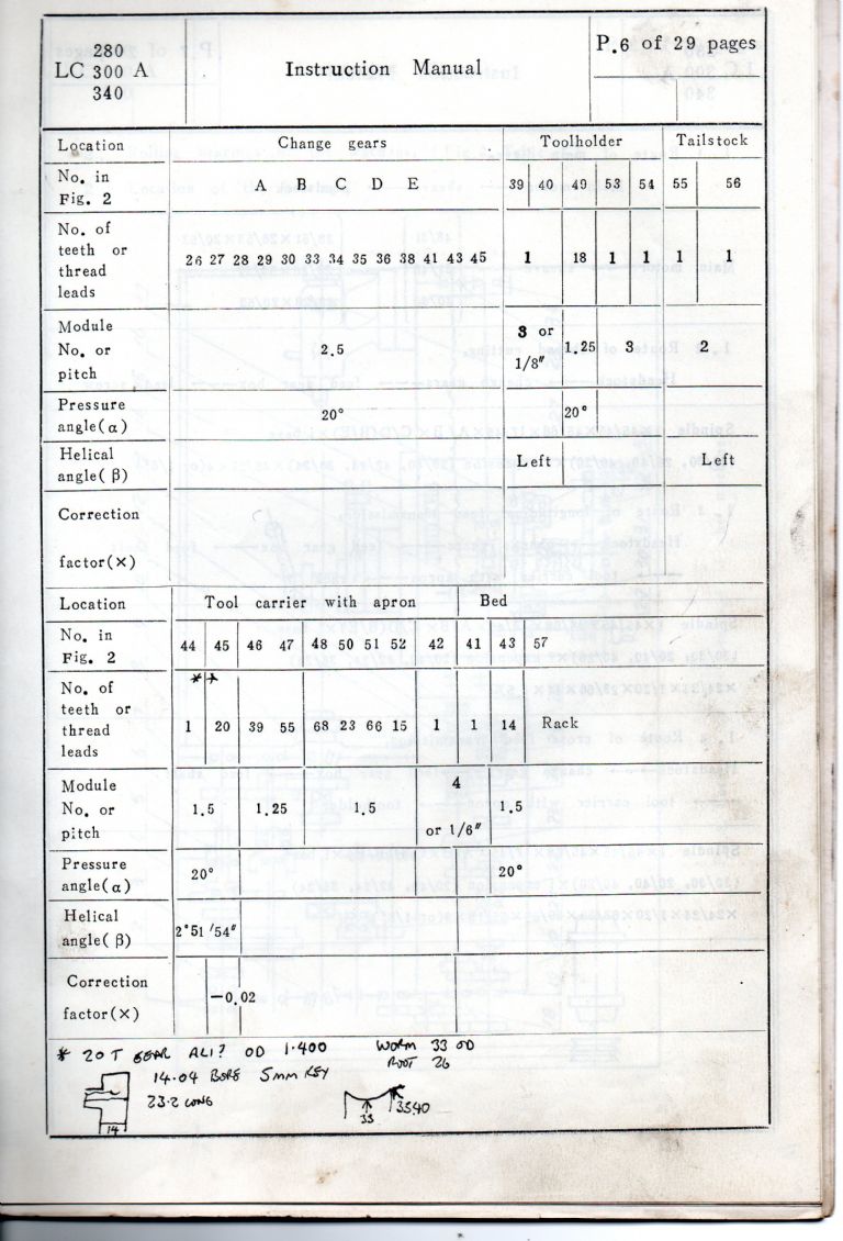
                                You should have the changewheels listed here as a set in the second line
                                down ,there is unlikely to be a 26 tooth i think is is a printing error as there
                                no listing in the changewheel setup for a 26 gear .

                                There are some differences between the Warco machines and the Chester
                                supplied ones , i see the motor is mounted now in the lower plinth ,mine
                                sits on the back of the lathe bed , the Warco machines have some small
                                tool lockers in the front and rear plinths.

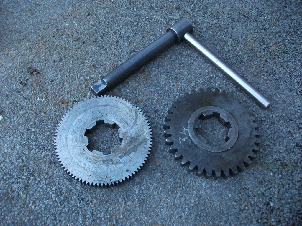
                                I guess the lathe itself will be very similar the changewheels have a six
                                spline hub as in the photo .the gear alongside is one of a set for a true
                                metric to imperial conversion and has a fabricated spline.

                                The key here is for the D1 5 socket ends the square is 11 mm and 13.5 mm
                                long the stem length is 130 mm ,unfortunately there are no markings to indicate
                                the closed positions of the cams as on some British machines and no detents
                                either to hold in the open position so you need to ensure the scribed lines
                                are in alignment before trying to remove the chuck.
                                They are clockwise to tighten i suppose you already know this ,it is just
                                possible that they may have been tightened up in the other direction they
                                will hold just not very well so just check as you will never get them off
                                if this is so.

                                Johnwarco gh1000 2.jpg

                                warco gh1000.jpg

                                #551837
                                Calum
                                Participant
                                  @calumgalleitch87969

                                  Well, the electrics are now hooked up, but the machine does not go brrrrr. I have gotten the multimeter out and checked there is indeed the vital electric juice running as far as the socket. I haven't tried the plug yet as I can't figure out how to dismantle it: it clearly requires a bit of force but I'm not sure where to apply it, and even I can't screw up wiring a plug that badly…

                                  This light, helpfully labelled "HL" on the panel: am I right in thinking that should illuminate when the machine is turned on?

                                  There is an isolator switch on the side of the machine, which I have remembered to turn on!

                                  I have looked at the microswitches on the guards and all seem to be in their working positions: have I missed any? I know about the chuck guard, change wheel cover, and footbrake. Are there any other ones I should check?

                                  Next step, I guess, is to open the electrics panel do a visual inspection, and start testing for the presence of electric juice within the box. I suppose there is a fair chance something has rattled loose in transit, though I hope not. I am hoping there is something daft I am overlooking, as opening the panel means moving the b***** thing again!

                                  Speaking of moving heavy things, the 10" 4 jaw has arrived. A little foxed, it would be fair to say, but it seems in decent nick. No key, but a half inch Allan key will fit.

                                  #551868
                                  Howard Lewis
                                  Participant
                                    @howardlewis46836

                                    Once you have the lathe up and running, you will be able to start checking that there is no twist in the bed.

                                    If the bed is twisted, it will tend to cut tapers.

                                    You can either compare the readings of the sensitive level, across the bed at both ends, or use the method advocated by Ian Bradley in "The Amateur's Workshop" ( See page 28 ) and "The Myford Series 7 Manual" ( See Page 42 )

                                    A 10" chuck is no lightweight. You may need to think about some sort of hoist that will allow you to swing it on and off the machine. making and fitting a wooden chuck board will be a useful insurance against damaging the bed, should it slip from the eye bolt, or sling that you use to support whilst fitting and removing.

                                    But first to start tracing how far the current goes through the circuitry. Multimeter to the fore.

                                    Howard

                                    #551874
                                    Meunier
                                    Participant
                                      @meunier
                                      Posted by Calum Galleitch on 29/06/2021 15:16:25:

                                      There is an isolator switch on the side of the machine, which I have remembered to turn on!

                                      I have looked at the microswitches on the guards and all seem to be in their working positions: have I missed any? I know about the chuck guard, change wheel cover, and footbrake. Are there any other ones I should check?

                                      One microswitch you may already have checked but haven't mentioned is the 'e-stop' the big red button to the right of your circled 'hl' switch.
                                      Push it in to break the circuit and twist it until it comes out.
                                      DaveD

                                      #551888
                                      Calum
                                      Participant
                                        @calumgalleitch87969

                                        Thanks Dave, I did check that but that's entirely the level of suggestion that I'm looking for, as I'm hoping it's something that simple! Warco did assure me it was running, so hopefully it's nowt tricky.

                                        Aye Howard, it's not a small lump of metal! Fortunately I'm a fairly big lump myself, but I might find myself making up one of Harold Hall's simple combination carrier and ways protector, and build it up a little so it's a short lift. At least with the camlock I can use both hands to get the thing in place.

                                        #551894
                                        Emgee
                                        Participant
                                          @emgee

                                          Callum

                                          The control circuit is transformer fed 24volts and as you say with power on 3 phases with the isolator ON and the 4A fuse is good the indicator should be illuminated, any other switch in the control cct would not prevent it coming on, unfortunately the total control cct is not shown on the drawing posted.

                                          Emgee

                                          #551989
                                          Calum
                                          Participant
                                            @calumgalleitch87969

                                            Thanks Emgee, I do have a couple more wiring diagrams though the quality is quite poor, so I'll hold off posting them for now, I don't want to cause anyone to try and pore through them with a magnifying glass unless I have to!

                                            #552470
                                            Calum
                                            Participant
                                              @calumgalleitch87969

                                              Well, turns out it was indeed simple. Once I got it away from the wall and the panel open, I noticed a couple of breakers inside, one for the main circuit and one for the control circuit. The control circuit was on but the main circuit was not. Pressed the button, turned the isolator switch on and we have life!

                                              Having pressed all the buttons and turned all the knobs everything seems to be there that should be. The gearbox is a bit fussy, requiring a bit of pushing or prodding or working out you need to come from the left or right to successfully engage a particular gear. I can't seem to find all the screwcutting gears, but that's not a major priority right now.

                                              I got the changewheels off, and I've got a 26, 27, 28, 30, and a 36, so I'll need to acquire the rest at some point. Again, not a major issue. Odd thing is that doesn't seem to be a listed combination for anything on the front panel charts!

                                              Next up is an oil change. On that front I see lots of people on Youtube using some sort of blue tape for rigging up drains and so forth – is there something people would recommend that's oil-resistant and suitable for the job?

                                              I'm also going to start putting together a small set of tools to keep handy for routine operation – spanner for changewheels, spanner for the compound slide clamping nuts (which themselves need renewed, as one at least is stripped). I also measured the camlock key which needs an 11mm square drive.

                                              #552480
                                              Meunier
                                              Participant
                                                @meunier

                                                Calum, good result !
                                                Warco GH1230 – probably similar general construction, oil change – I tried the tape and aquarium tube trick – big mess rapidly abandoned. Removed the top cover to the headstock and syphoned out the oil contents – mopped up the dregs, ran a magnet round the bottom, refilled through the top and replaced top cover – much easier and (much ) less messy.
                                                DaveD

                                                #552506
                                                Howard Lewis
                                                Participant
                                                  @howardlewis46836

                                                  So you are almost ready to go!.

                                                  Once you have the changewheels, probably find a chart listed for the machine, on Google, (Grizzly perhaps? ) can be found., to give the feed rates and standard thread pitches that are available.

                                                  Howard

                                                  #552574
                                                  Calum
                                                  Participant
                                                    @calumgalleitch87969

                                                    Sorry Howard, I was a bit vague – I've got the charts on the front of the lathe – what puzzles me slightly is that the combination of wheels I have isn't actually one of the listed combinations.

                                                    For new changewheels, are Warco/Chester likely to stock stuff like this as parts? Or is it a case of buying a module cutter and dividing head and getting on with it?!

                                                    The other thing I forgot to mention is the footbrake doesn't activate the emergency stop, which is obviously less than ideal. I'm not inclined to worry too much about it – the control lever is right there anyway. One for the snagging list!

                                                    #552586
                                                    Howard Lewis
                                                    Participant
                                                      @howardlewis46836

                                                      Hopefully, Warco, or Chester may still stock any gear that is missing.

                                                      Having a Norton box, you won't need as many changewheels.

                                                      My lathe has a Norton box giving 48 possibilities and the changed from Imperial to Metric usually requires just a 120 /127T idler to be moved. For some metric pitches the normal 40T input gear has to be changed to a 32T.

                                                      If you take the measurements of some of your changewheels, you MAY find some from another machinje that can be adapted, possibly by boring out or bushing the centre or modifying the keyway, (Either widening and deepening the current one, or cutting a second, narrower and shallower keyway on the opposite side of the bore.

                                                      (See below, to find the Module, and what Arc Euro, or Axminster could offer as spares for say, a Sieg C6 lathe.

                                                      My lathe also came with a spare 30T gear, which when used to replace, fortunately, the standard 40T as the first driver in the train, allowed a 4 mm pitch to be cut..

                                                      Wanting to halve the standard finest feed rate.0.0047" (0.120 mm) and having a Rotary Table and Dividing plates, I bought a 1.25 Mod cutter and made a 80T for the input gear to the Norton box, In my case, this required relocating the fastening for the gear cover. A 20T first driver would have been too small over the shaft.

                                                      Presumably you already know how to find the Module of the gears?

                                                      If not: Measure OD, Count teeth, Add 2, and divide that number by the OD.

                                                      Thus a 1 Module 60T gear will be 62 mm diameter. A 1.5 Module 60T gear would be 93 mm diameter.

                                                      Ivan Law's book "Gears and Gear Cutting", No.17 in the Workshop Practice Series is a useful aid when you start cutting gears.

                                                      HTH

                                                      Howard

                                                    Viewing 25 posts - 26 through 50 (of 69 total)
                                                    • Please log in to reply to this topic. Registering is free and easy using the links on the menu at the top of this page.

                                                    Advert

                                                    Latest Replies

                                                    Home Forums Manual machine tools Topics

                                                    Viewing 25 topics - 1 through 25 (of 25 total)
                                                    Viewing 25 topics - 1 through 25 (of 25 total)

                                                    View full reply list.

                                                    Advert

                                                    Newsletter Sign-up