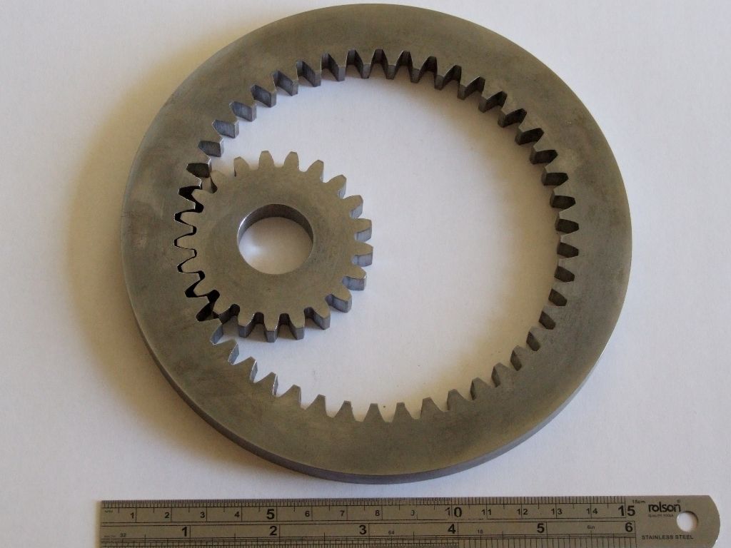
Some years ago I made the internal gears that bolt onto the inside of the hind wheels for my Burrell-Boydell engine using the method outlined below;>>
"The engine is driven by pinions on the ends of the crankshaft, which mesh with internal gears fastened to the inside of the hind wheels. The method of engaging gear is to use two handwheels (not visible on the picture) to raise the rear of the boiler so putting the pinions into mesh.>>
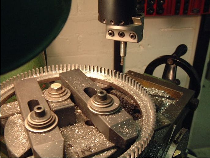
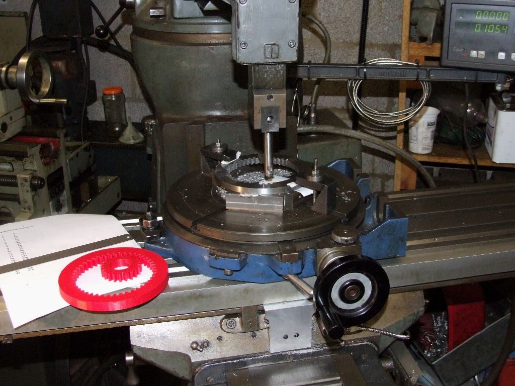
The problem arises as to how to machine these gears, which are over 8 ½ inches in diameter. After discarding the idea of cutting them as racks and curving them in the same way as the steering quadrant, it was decided to cut them from solid as the picture below shows. Lady luck was smiling as I found 2 flame-cut rings in the scrap box that were just right.>>
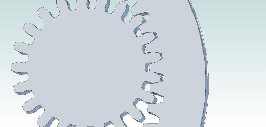
The slots were cut through using a 1/8 in slot drill (well, 3 actually) and then the boring head was set up as shown to curve the flanks over three teeth to produce a reasonable shape to the teeth. A ring will then be silver soldered to the outside to provide the ‘bottom of the teeth.>>
 ">>
">>
I'm now looking to cut the pinions to mesh with these and, looking at things afresh, realise that my original thinking of approximately 16DP was incorrect. >>
Looking at the gear form it looks more like 14 DP and I will need to make a cutter.>>
The snag is that I cannot work out the maths with any degree of certainty, hence this plea for help. Perfection is not required, just the hope that the gears mate sufficiently to provide drive.>>
The internal gears are 8.5" ins. PCD with 108 teeth with a pitch of 0.240" ins. The OD of the pinion needs to be approx 7/8 ins. (because of the way it all fits together) and I make the number of teeth required on the pinion to be 9, which is outside the calculations in the books I have.>>
Any assistance would be gratefully received and acknowledged.>>
Brian>>
Anonymous.


