Help in identifying antique milling machine.

Advert

Help in identifying antique milling machine.

Home Forums General Questions Help in identifying antique milling machine.

Viewing 25 posts - 1 through 25 (of 30 total)
  • Author
    Posts
  • #571639
    Michael Minas
    Participant
      @michaelminas99836

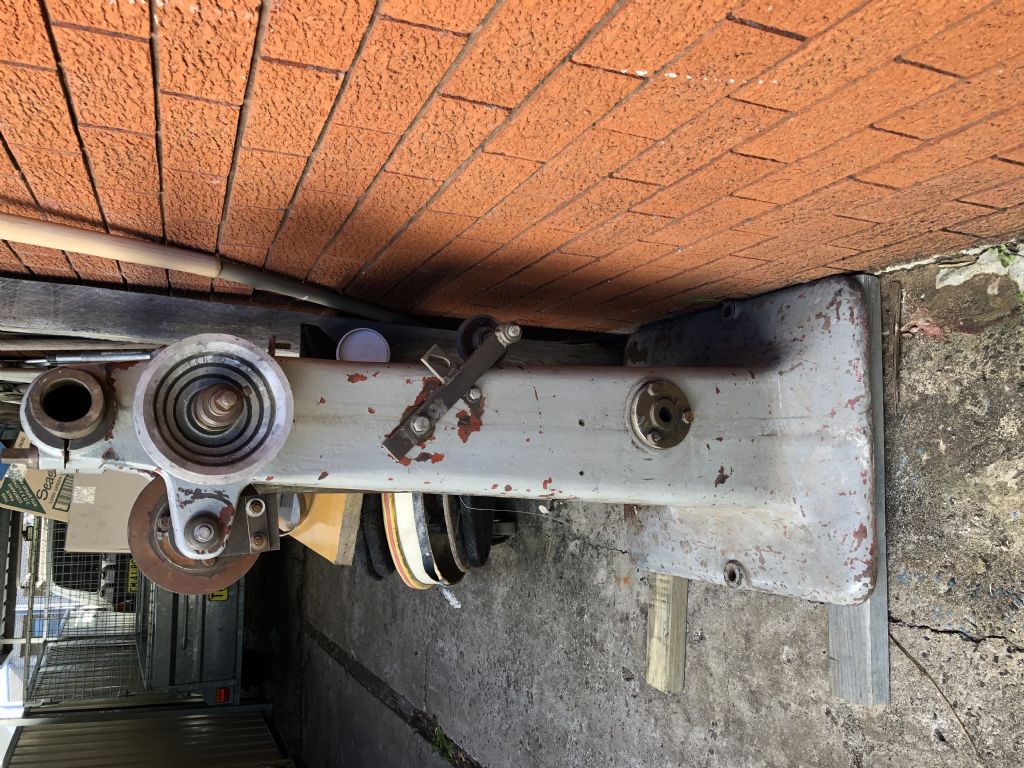
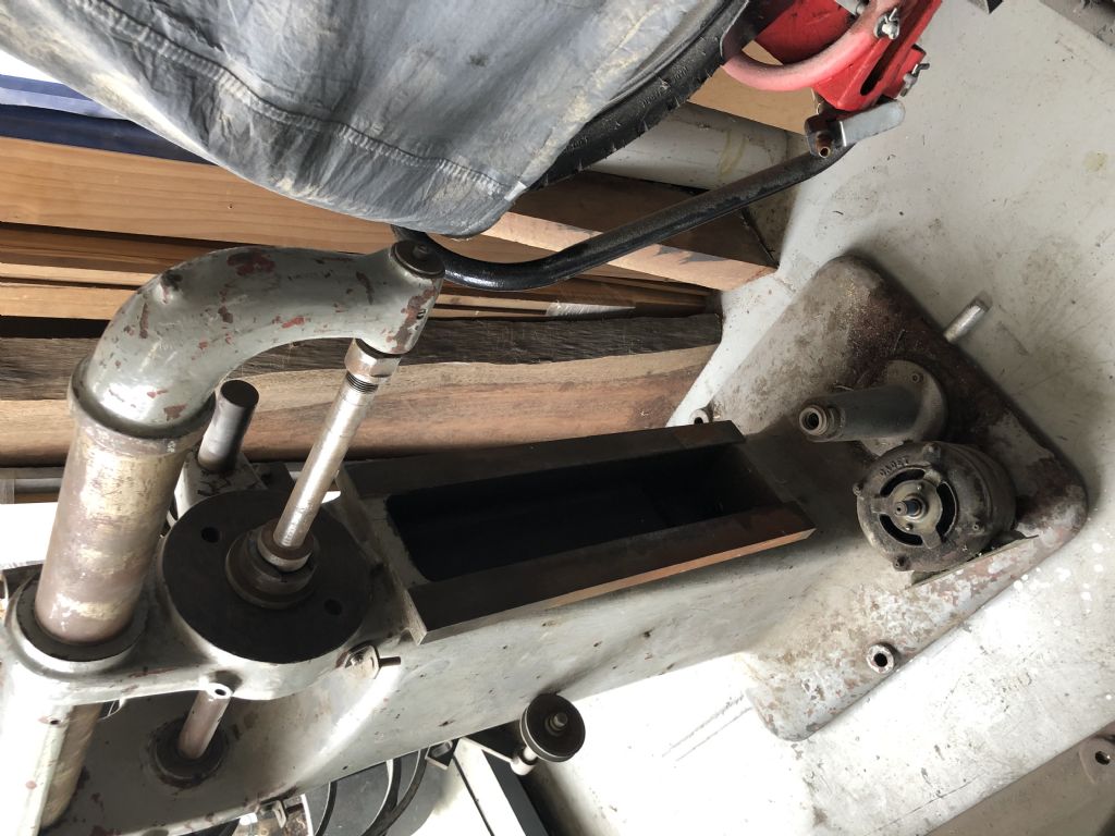
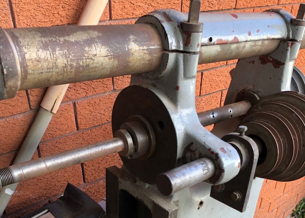
      img_1590.jpgimg_1585.jpgGreetings from a new member over here in Australia. I am hoping the collective knowledge on this site can help me identify an old milling machine I want to restore.

      I have tried forums her and in the US with not much luck. I have also thoroughly looked at vintage machinery and lathes UK but no luck. This is getting harder than I thought.

      I will attempt to load some photos and see what happens.

      Any help would be greatly appreciated.

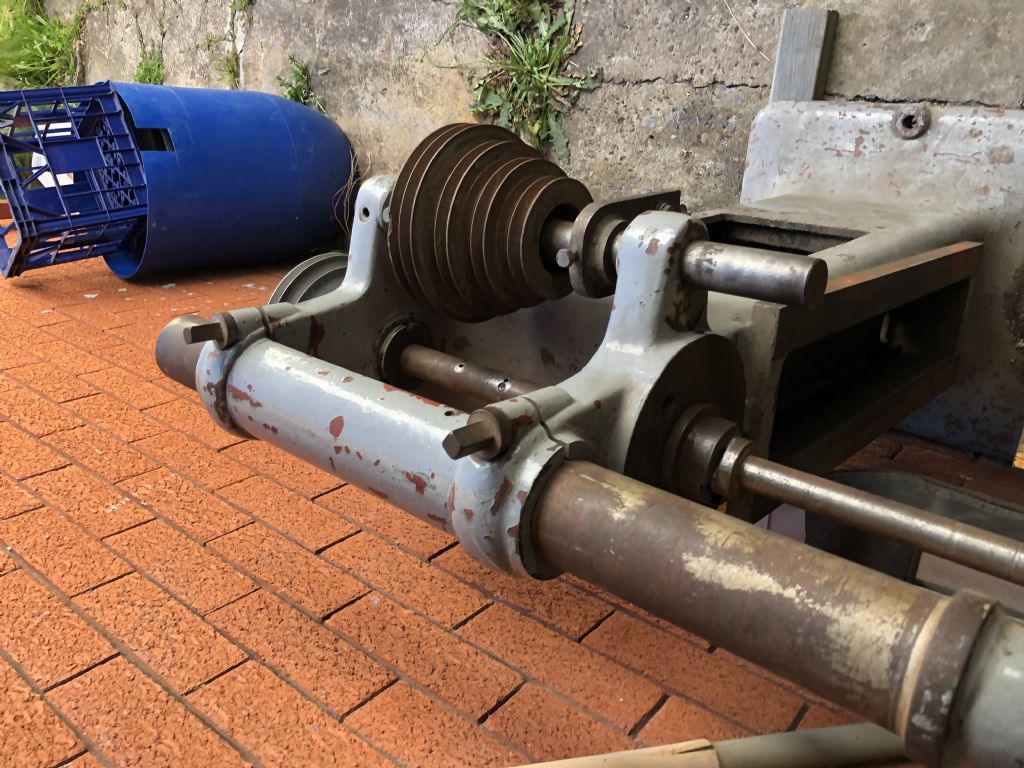
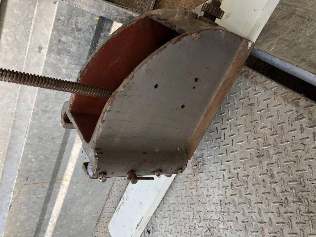
      img_1593.jpgimg_1581.jpg

      Edited By JasonB on 17/11/2021 07:28:20

      Advert
      #28440
      Michael Minas
      Participant
        @michaelminas99836
        #571649
        Chris Evans 6
        Participant
          @chrisevans6

          Thiel ? certainly older than anything I have used.

          #571651
          roy entwistle
          Participant
            @royentwistle24699

            Pooles ?

            #571654
            IanT
            Participant
              @iant

              Has some simliarites to a Pallas mill but I think this one is a little larger and the Pallas has a seperate countershaft. May be from the same family though.

              I have a Pallas 'column' in the Shed – one of those projects that was overtaken by events…

              Regards,

              IanT

              #571702
              Thor 🇳🇴
              Participant
                @thor

                If there is no indication of the manufacturer on the machine it may be difficult, the only one resembling yours, that I have managed to find is Birch (lathes.co.uk)

                Thor

                #571741
                DiogenesII
                Participant
                  @diogenesii

                  ..it's similar to (but not0 a Burke – there were several small American mills of a very similar style all around at about the same time, these often use a Brown & Sharp taper in the arbor – the sizes are very close to Morse, some careful measurement might be needed to establish what you have..

                  Edited By DiogenesII on 17/11/2021 17:57:33

                  #571748
                  peter smith 5
                  Participant
                    @petersmith5

                    Denby or Denbeigh. Origen USA, but some made in uk under licence. I had one very similar. Previous owner had welded a “ vertical head” onto the end of the overarm and bolted a motor onto the back One speed via belt and pulley. Shame the head was at 93 degrees.
                    After a lot of work, remachining the head I used the 3 step pulleys and back gear from a ML10, refaced the table and managed to get rid of most of the backlash.

                    The major problem was that the longitudinal and cross feeds turned the wrong way but it was all I could afford at the time. I donated it after 10 plus years to a friend who makes fairground type organs as a dedicated wood Miller making pockets for reeds.

                    it appeared in catalogues pre 1910 but not in the 1920’s.

                    #571751
                    DiogenesII
                    Participant
                      @diogenesii

                      It is very similar to the Birch.. ..do you what taper it has? ..and what threads the fasteners use ..it might provide a clue..

                      #571756
                      Clive Foster
                      Participant
                        @clivefoster55965

                        The one piece half circle casting clamping the round overarm down to the two separate support standards is unusual and, probably, a unique identifier.

                        However it is in general design a very generic small, lighter duty horizontal mill for its era. Quite possibly never marketed under a manufacturer name being supplied direct to large tool merchants and machine resellers who would have their own branding applied. Possibly via a bespoke door casting to cover the hole in the side of the plinth.

                        When new it would most likely have been flat belt drive via lineshaft. The multi step Vee pulleys will be later additions indicating that its been modified at least once in its (long) life.

                        Clive

                        #571760
                        Dave Halford
                        Participant
                          @davehalford22513

                          It may like the last Centec2, the rights and moulds sold on to a new maker (Granville) these had no cast in names at all, but are unmistakably Centec apart from the knee.

                          #571766
                          Bazyle
                          Participant
                            @bazyle

                            And it is a universal from what I can see of the table so that reduces the options from cheap hobby to small production machine. The release leaver for the table is perhaps unusual.

                            #571771
                            not done it yet
                            Participant
                              @notdoneityet

                              I would start with threads. Metric, imperial (UNC or Whit).

                              If imperial, check the 1/2 inch bolts/set screws as they will be different tpi.

                              The motor may even be original and offer some clue (frequency, voltage, power, method of wiring).

                              Dimensions of parts – support bar, shafts, pulleys, for instance. Bolt hole separation for the base. May be others.

                              All useful for a guess as to origin, even if there is no manufacturer’s name.

                              #571777
                              peter smith 5
                              Participant
                                @petersmith5

                                On mine the threads were USA, and the name was cast onto the door. If going to be badged it would be easier to just change the door.

                                #571782
                                John McNamara
                                Participant
                                  @johnmcnamara74883

                                  Both Browne & Sharpe and Pratt and Whitney made similar machines.

                                  **LINK**

                                  Many companies made similar machines

                                  An assembled photo might help identify it.
                                  Are the parts numbered?

                                  Vintage machinery.org have free downloadable documents from that era. the best site I know of for old US metalworking machines.

                                  **LINK**

                                  #571793
                                  Michael Minas
                                  Participant
                                    @michaelminas99836

                                    Thank you so much for all your replies. I believe I am one step closer to finding out what make it is or one step closer for stopping my search.

                                    I think Clive is spot on. Probably a generic machine marketed under various names. Probably why the name is on the door. The more prestigious manufacturers of that era had names cast on the machine, Cincinnatti, Browne and Sharpe etc. Im curious to know why you think this machine was made in the USA? For sure this was a line shaft machine and the pulleys a later addition.

                                    Still, the overarm support and vertical bolts are defenitely unique. Not sure how many manufacturers in that era used box ways. Machine threads are all UNC. I have yet to locate any numbered parts.

                                    I would like to begin assembling the machine but thought I would try to find a manufacturer to get it right. I would appreciate some guidance if possible. Not sure how the belts, pulleys etc are all organised.

                                    To be honest I didnt need another machine but I purchased a small surface grinder and this machine was thrown in for $200 AUS (about 100 pounds sterling. Plus it has a Victor Universal head that fits to the drive shaft. I couldnt say no and now it has grown on me. A horizontal mill would be a great addition to my little home hobby shop. The history is also fascinating.

                                    #571794
                                    Michael Minas
                                    Participant
                                      @michaelminas99836

                                      Heres a few more pictures.

                                      img_1592.jpgimg_1588.jpgimg_1589.jpgimg_1591 (2).jpgimg_1594.jpgimg_1587.jpg

                                      #571897
                                      peak4
                                      Participant
                                        @peak4
                                        #571907
                                        Nigel Graham 2
                                        Participant
                                          @nigelgraham2

                                          It looks very much like a development of the Denbigh H4 or a machine based on it (I own an H4); introduced in the 1930s or 1940s. (See the Denbigh chapter on lathes.co; ) They were not built as hobby machines but for small industrial production work.

                                          However,

                                          If Denbigh it will have the trade-mark Staffordshire Knot embossed on the side of the column, and the door in the stand. Denbigh was an English, not American, company, based in that county whose emblem is that knot.

                                          It will also have a 3 Morse taper spindle; Whitworth bolts generally, and 2BA screws holding the flanged knee-screw nut to its column. Mine at least has a solid, not tubular, over-arm.

                                          The H4s were made for bench mounting or bolting to a separate stand that on its own rather resembles a cast-iron khazi, with a trade-marked door in its side. The cupboard appears designed to swallow small items amnd not give them up!

                                          They were fitted with flat-belt pulleys on the spindle itself for overhead drive, though Denbigh also sold a confection in iron to allow such a machine to run from its own motor. No cast-in side-arms for V-pulleys.

                                          Also the H-series were not universal mills – or at any rate, those on the lathes site are not; and nor is mine.

                                          That peculiar drop-bracket and the side countershaft do not tally with Tony Griffith's archive photos although my own version has some differences from them too.

                                          Mine has also lost its drop-bracket so I can't compare that.

                                          Denbigh was involved in the badge-engineering trade so this one could be from almost anywhere; but I recall seeing one much more like my and the archive-pictured H4s, superbly restored and much "breathed on", displayed at one of the Sandown exhibitions (are we allowed to mention them here?). That machine had a different name on its main casting though – "Patrick" if I remember aright. It was also fitted with what seemed a back-gear but I don't recall if that used an original mounting (as on yours) or specially-built.

                                          One curious aspect of my Denbigh H4 is that two of the feed-screws are 6TPI but the other, 8TPI. I forget off-hand which. I do not know if this was standard for that design or to some special order.

                                          '

                                          The Hs 1-3 were simpler machines with lever-operated long feeds. The H4 has power-feed drive originally from a 3-step flat-belt pulley pair on the back of the machine. Mine is lost but the mounting-pad on the casting is clear.

                                          Edited By Nigel Graham 2 on 18/11/2021 22:39:38

                                          #571936
                                          Michael Minas
                                          Participant
                                            @michaelminas99836

                                            Thanks again for all the information. All those machines are close but still there are distinctive differences. I was wondering if anyone has seen a base like mine with only two holes that have a small raised section around each on another machine? Lathe, tool grinder etc. It could be an indication of a manufacturer.

                                            Nigel I will have a look at shafts and fixtures tomorrow and take some pictures. What do you mean by drop bracket? Forgive all my questions but not quite familiar with this type of machine.

                                            #571961
                                            Nigel Graham 2
                                            Participant
                                              @nigelgraham2

                                              A pleasure to help, Michael!

                                              Base: the holes, with bosses to give proper flat surfaces for the fasteners, are of course for bolting the machine to the workshop floor, but just two like that is very unusual – I would expect 4, one in each corner, on any make of machine. (As mine has. I used self-tapping concrete-screws with big washers to secure it.) Perhaps they had "value engineers" even in the 1930s!

                                              I see the column for the elevating-screw is held with socket-head screws. they bain't be from round 'ere! Maybe someone lost the original hex-headed set-screws at some point in the mill's life, and it's possible the holes have been re-tapped or fitted with thread inserts.

                                              '

                                              "Drop bracket" – at least that's what I've always known it as

                                              Start with the over-arm, to set the terms' context. That is the long bar or tube clamped right along the top of the machine, adjustable for projection.

                                              The "drop-bracket" is the fitting on the over-arm's outer end, that carries a bearing (usually a plain bush) concentric with the spindle, to support the outer end of the bar that carries the cutter. The arrangement is somewhat similar to using a boring-bar between centres on a lathe.

                                              On your milling-machine then, it is the rather elegant curved casting that makes me think of a musical instrument! These fittings are usually a more functional polygon though on the original H-series it was a rounded casting like a figure-of-eight in profile. Your 4th photo down shows it all assembled except for a cutter, and though hard to tell it looks as if the cutter spacers are all on the cutter bar itself.

                                              The spacers give you two possibilities: mounting a cutter at an appropriate, approximate distance along the bar, and to give an accurate gap between two ("ganged&quot cutters, for. e.g. making T-nuts, or end-squares/hexagons on the end of cylindrical work.
                                              #572083
                                              Michael Minas
                                              Participant
                                                @michaelminas99836

                                                Heres some more photos. Starting to think that maybe this machine was actually made here in Australia. See attached a picture of a lathe with a similar base/column. Apparently machines where made her by companies, sadly there is not much information available.

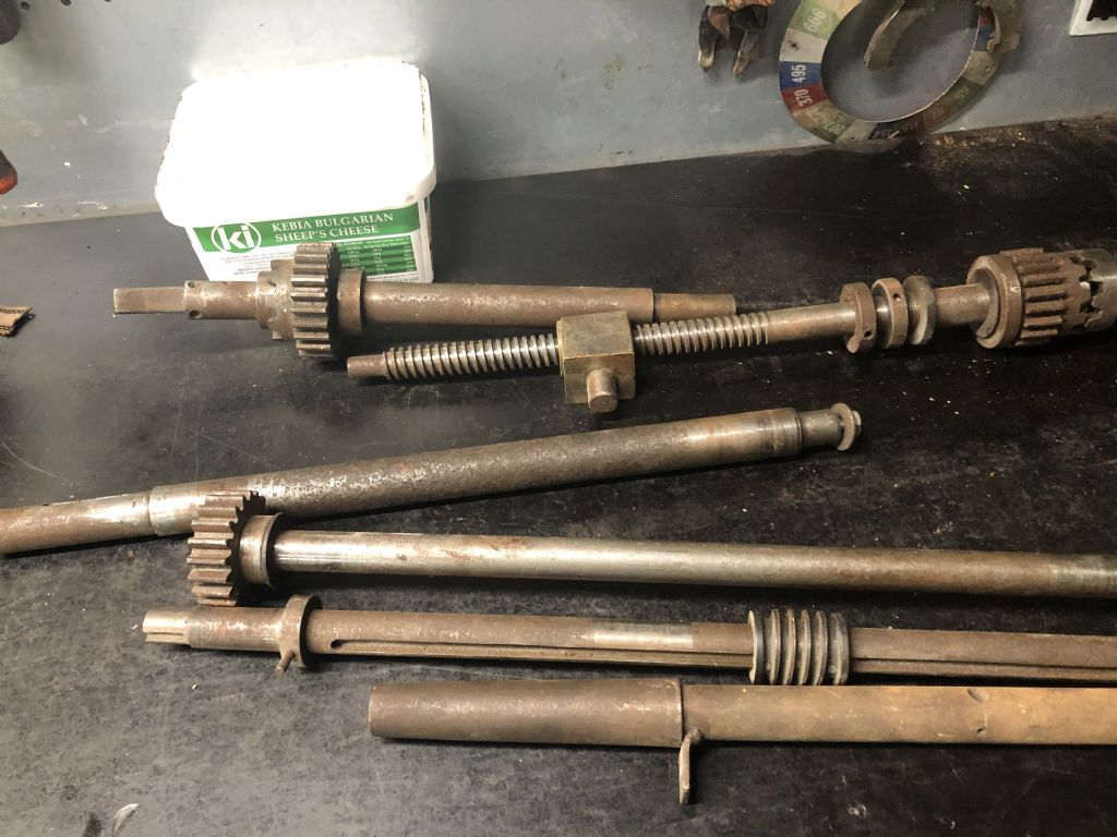
                                                I have no idea how these shafts and gears will all go together but im sure will figure it out as I go along.

                                                img_1637.jpgimg_1655.jpgimg_1656.jpgimg_1659.jpgimg_1660.jpg

                                                #572216
                                                Nigel Graham 2
                                                Participant
                                                  @nigelgraham2

                                                  Oh Hell! I wrote a few lines, returned to look again at your first set of pictures and that action deleted what I'd written.

                                                  The lathe looks a bit like an Ehrlich, or influenced by that make. (I owned one, fully-equipped, but subsequently donated it to Lynton & Barstaple Railway for its workshop. I sometimes wish I still had it!)

                                                  '

                                                  Looking at your later set of photos of parts, if they are from the milling-machine:

                                                  Of the several shafts –

                                                  – That nearest the camera seems to have a tapered end – if so it is a carrier-bar for cutters but should not have those dimples drilled in it, though may have a keyway. We can't see the other end but if I have indentified it correctly it will have a short threaded portion (for the cutter clamping-nut) and a spigot to match the drop-bracket bearing. The nut may be inside or outside the bracket, depending on design. On my Denbigh the nut is inboard of the drop-bracket.

                                                  – I thought its neighbour with the long keyway might be the longitudinal feed shaft but I would expect that instead to be a screw (square or Acme thread), not plain.

                                                  – The top two look as they work together. The screw and nut appear to be for the cross-feed, with a power-drive engaged by the dog-clutch just visible in the picture to allowing using the machine as a horizontal borer – a potentially very useful feature despite the limited travel. If so, the shaft above it may be for manual drive when setting the table across for normal horizontal milling (longitudinal feed only). If so the square might allow a loose handle removed for safety when the power cross-feed is engaged. A further clue to this is the pinion on the knee (first photos).

                                                  – I can't identify the rest but they should yield to careful examination.

                                                  '

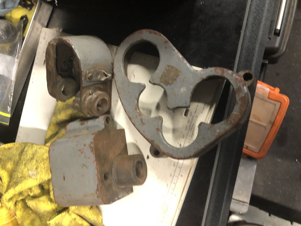
                                                  Of the three "sculptures " –

                                                  – The large one with four conjoined holes is a guard, possibly over the power-feed gears.

                                                  – The U-shaped casting appears to carry a shaft through it, and my thought is that it carries the long-feed worm and wheel, or in this machine perhaps the spiral bevel mate for that lying on the inverted table in your first set of photos.

                                                  – The hefty block does seem to have a bearing bush in its boss, but beyond that I do not know! Still, it clearly fits a machined surface with matching holes so it should be fairly simple to identify!

                                                  '

                                                  To set the above in context, the way these typically work is :

                                                  The main table runs across the cross-feed saddle; and the latter carries a lug holding the longitudinal feed-nut (see your first photos).

                                                  The feed-screw runs the length of the main table, passing through that nut; and its ends protrude through thrust-bearings in or on the table-ends, to take a handle on one or both ends for manual control.

                                                  Riding on the end of the feed-screw, and often inside the table's cavity, is a worm-wheel (or here spiral-bevel?), with an elongated boss whose through-bore is keyed to engage the keyway running most of the screw's length. This gear is restrained so it stays in a fixed position relative to the cross-table. The feed-screw thus runs through the worm-wheel but the two parts revolve together.

                                                  The mating worm or instead driving-gear is revolved by a telescopic shaft with paired universal-joints to cope with the knee's vertical range; and driven by stepped pulleys or change-wheels from the main spindle.

                                                  The worm or gear is out of engagement by default, allowing the table to be moved manually, and is brought into play by a short handle raising it on a sprung or gravity catch. This can be released manually or by an adjustable trip-block commonly carried in its own T-slot along the front face of the main table. The adjustable trip allows repeatable, defined cuts under power-feed, such as when fluting an engine connecting-rod.

                                                  '

                                                  Now looking at the other photos –

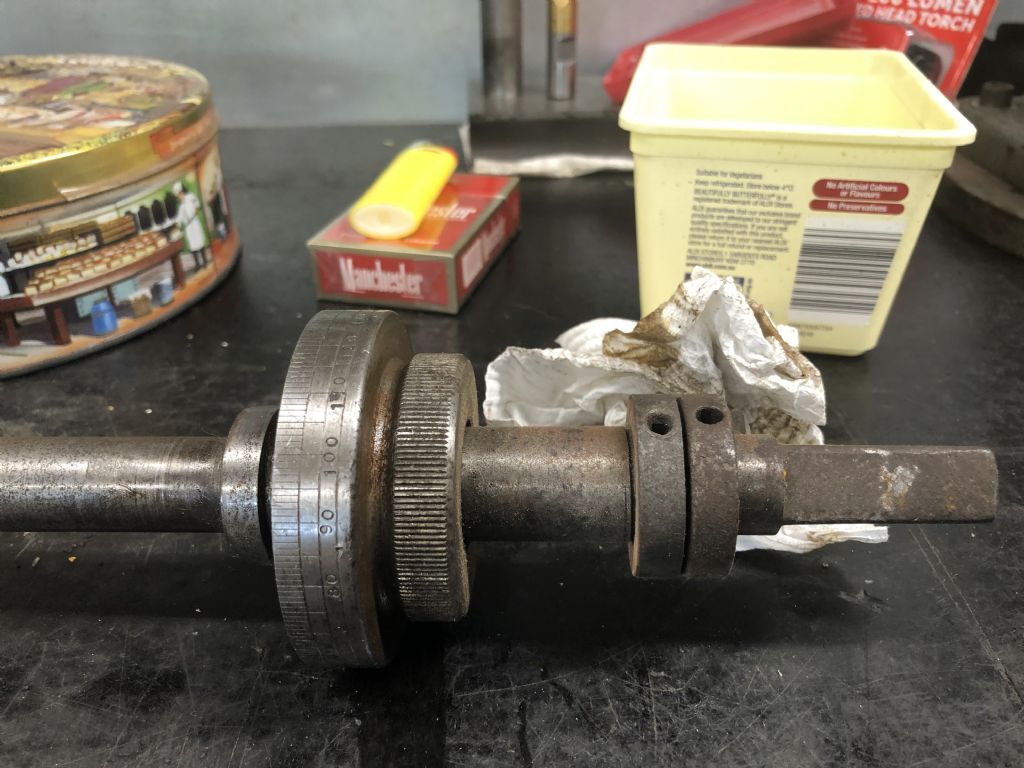
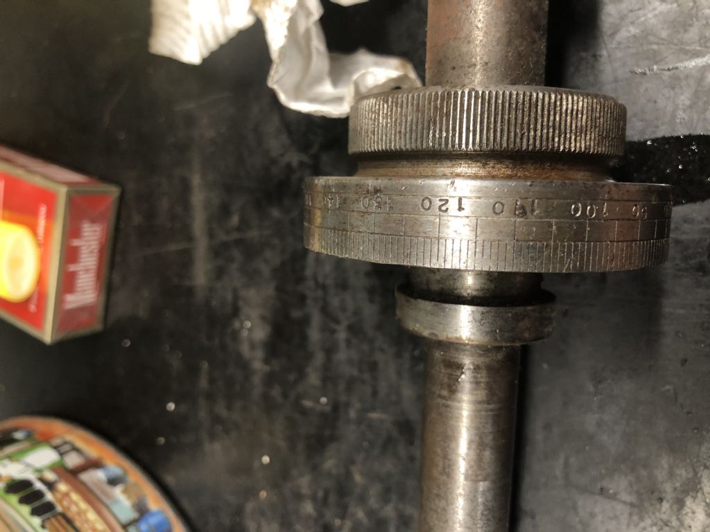
                                                  The straight-knurled discs next to the calibrated dials suggest settable dials, a feature I wish all machine-tools had! With only the dials visible I can't say what two of the three feed-screws they are on, but each will occupy only its appointed station in life.

                                                  #572248
                                                  Michael Minas
                                                  Participant
                                                    @michaelminas99836

                                                    Thanks again Nigel. Im slowly getting my head around it.

                                                    The more I think about the two holes on the base the more I believe that this casting could have been made or modified for a lathe. In all my research I have yet to see a horizontal mill with only two holes in the base.

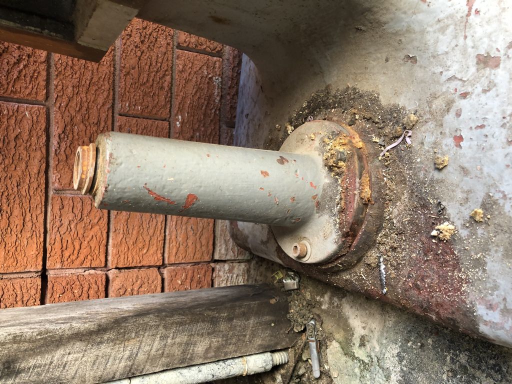
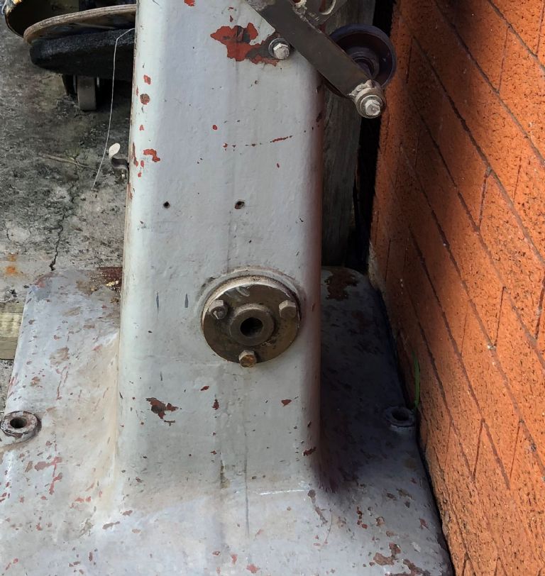
                                                    Could you tell me what is supposed to fit into the hole with the bronze bushing located at the rear of the column, near the bottom just off centre. The hole runs through to the front cavity just behind where the knee would be located. I will attach photo.

                                                    img_1593 (3).jpg

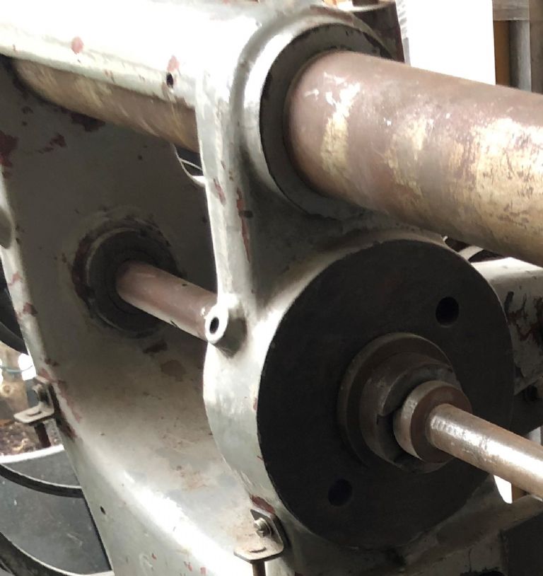
                                                    I believe the two holes on the left hand side of the casting at approximately 45 degrees, in line with the shaft are for oilers?

                                                    img_1581 (2).jpg

                                                    Im not sure where the previous owner had located the motor but I believe it was below the back gear shaft. Is this the best place for it? Or does someone have a better suggestion? I will be fitting a 2.5hp DC 3phase motor with a VFD. Just trying to reduce the array of belts and pulleys.

                                                    I could also try and remove some of the pulleys and replace with gears. I have a few large and small ones tucked away somewhere. Is that a better option? Would like to see some setups.

                                                    #572262
                                                    Nigel Graham 2
                                                    Participant
                                                      @nigelgraham2

                                                      The casting is a single-piece and made for that milling-machine, but given the similarities might have been by the same manufacturer as your lathe.

                                                      The bush at the bottom, and its mate on the front, are clearly original because the one photographed is on a faced boss on the casting. My guess is that the machine was originally built for line-shaft drive via a primary pulley that used the bush, then up to the secondary shaft on the two bearers to the side of the spindle. This was fairly common practice and allowed a greater speed reduction from the line-shaft. Maybe one of those shafts in your previous photos fits there.

                                                      In restoring my Denbigh mill of sumilar appearance and vintage to service, I am faced with the same problem of speed, having calculated the necessary spindle rpm range as from about 70 to 120 rpm.

                                                      What we don't really know either is what is meant to connect the side-shaft to the spindle. Those V-belt pulleys should be fine though I doubt they are original. It might have had a 2-speed gear drive or a back-gear type speed reducing gear. Whatever it was, it used only set-screws or grub-screws as their dimples in the spindle are clearly visible. You could use gears but you've then the problem of either selecting gears to match the existing centres for correct meshing or making some sort of carrier-frame – difficult to acheive without a lot of work and risking a rather ungainly result.

                                                      The two arms dangling from the side-shaft look like a modification, probably carrying a belt-tensioning roller.

                                                      [Carefully saves this text to be able to refer to photo set 1…]

                                                      '

                                                      I am coming to think that in its original guise, comparing yours to sample machines in old catalogues and text-books:

                                                      The primary drive was an overhead line-shaft or separately-mounted motor with stepped pulleys, to a shaft in the base of the column. A second belt then either –

                                                      – ran to one on the rear end of the spindle, and the side-shaft carried a back gear, or

                                                      – to the side-shaft then gears or a further pulley pair to the spindle.

                                                      Of those I favour the former but you might find problems sourcing gears to match the rigidly- set centres if you replace the V-pulleys. If you keep that belt final drive you will need replace the tension roller if it is missing. I would also recommend you place the motor high above swarf and dust (as I have with my Harrison lathe), and to allow a large single-step belt reduction with sufficient wrap on the smaller pulley. Use just one, twin-belt for that primary drive, and fit the driven pulley either within the frame or if external, as close as possible to the bearing to minimise the overhanging load on the shaft.

                                                      You will need a large mechanical speed-reduction, because motors do not like running slowly. I am not sure if as some say, this is because their fans beome inefficient or for some electrical reason.

                                                      The Newton-Tesla VFD sets on Myford 7 and Harrison L5 lathes keep the motor happy at 900-1000rpm even with the machine itself, on its lowest mechanical speeds, running at <100rpm. (I estimate by eye, 60-70rpm on the Harrison). The speed controls' Green advisory sectors are high up on the scale.

                                                      One option for a partly-geared drive (as I may use on my comparable example) is to put the gears at the motor end, or in between a primary and secondary belt. That allows making a gearbox to suit the application, using readily-available gears and minimal changes to the machine itself.

                                                      Belt drives tend to be quieter than fast-running spur gears, too, but more to the point give some warning and protection by slipping if something jams or you accidentally over-load the cutter.

                                                      2.5HP…. Large for a machine like that, especially with the torque-multiplying given by the heavy speed reduction; risking inadvertently overloading a relatively light machine with small shafts running in plain bearings. My Denbigh will have a 1HP single-phase motor I obtained long ago, and though my other machines have 3-ph conversions I don't envisage that necessary for a small horizontal mill. I may need limit the cutters' maximum diameters, widths and feed rates but that's not a problem.

                                                      You could fit the motor below the shaft as you suggest but that is a bit close to swarf and cutting-fluid. It is better somewhere above the machine.

                                                      '

                                                      The small holes at 45º – for oil? Yes. When you remove the spindle, ensure they are clear and clean through. I do not know if they originally held proper oilers but that would be a good idea, if only a simple lid to keep dirt out.

                                                      A puzzle feature on my machine is a small lug with vertical blind hole, on the side opposite the corresponding front oil-hole. It may have been to hold a lamp, possibly offered as an extra – no reason I could not use it thus.

                                                      .

                                                      Mine has its original 3-step flat-belt pulley on the spindle, with a large grub-screw accessible through a hole in the pulley face – a previous owner had bolted a modified motorcyle sprocket to that pulley, for a chain-drive from a motor and ancient car gearbox on an overhead frame. It does not have a side-shaft, nor provision for an intermediate shaft low down, because the Denbigh H-series mills were for fitting to a separately-supplied stand or customer-built bench.

                                                      I'm contemplating a belt drive to reduction-gears, then belt final-drive. Alternatively, my two gear-pairs available, on the spindle and on a side-shaft on swing-arms with bearings on the spindle, controlled by a side-frame mounted on the original machine-to-stand fastenings. A a geared final drive / Lenix-pattern belt-tensioning, from a motor above the machine. The feed needs replacing completely, and is driven from the spindle's rearward extension.

                                                    Viewing 25 posts - 1 through 25 (of 30 total)
                                                    • Please log in to reply to this topic. Registering is free and easy using the links on the menu at the top of this page.

                                                    Advert

                                                    Latest Replies

                                                    Home Forums General Questions Topics

                                                    Viewing 25 topics - 1 through 25 (of 25 total)
                                                    Viewing 25 topics - 1 through 25 (of 25 total)

                                                    View full reply list.

                                                    Advert

                                                    Newsletter Sign-up