grayson lathe rebuild

Advert

grayson lathe rebuild

Home Forums Manual machine tools grayson lathe rebuild

Viewing 25 posts - 1 through 25 (of 35 total)
  • Author
    Posts
  • #226564
    dave george 1
    Participant
      @davegeorge1

      hi all,ive been given a grayson lathe to restore,ive stripped it all down,made an electrolisis bath and put everything of the lathe in there,got the lathe back to bare metal and gave it all a coat of zinc phosphate primer.while i was priming the tailstock i noticed they wasnt any grub screws to off-set the tailstock,so that when i started googling and came across a thread a few years ago on here

      http://www.model-engineer.co.uk/forums/postings.asp?th=79515

      now this thread hasnt been updated,and wondering if the guy got it sorted,as i seem to have the same problem

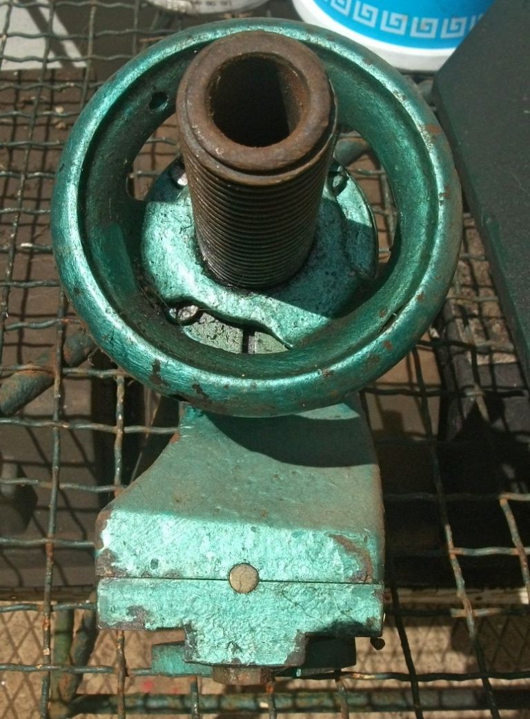
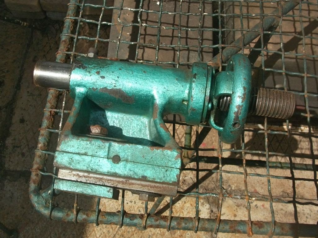
      ive been racking my brains about it,whether it had a plate inside the tailstock to move it left or right and up and down,but i noticed in the tailstock they are 3 tapered slots,and a bolt going thru it all to hold it all together,making it type of a fixed tailstock,the other bolt hold is to hold the tailstock onto the lathe bed

      also ive been in touch with tony from lathes.co.uk and he couldnt help me,ive spoke to a few old timers engineers (70-80 year old) and they didnt have a clue

      please take a look at the pictures and see what you think

      thanks

      https://www.dropbox.com/sh/mdqaivorprrukw9/AADzCiXUkJY83jPjqDgunL9La?dl=0

      Advert
      #12636
      dave george 1
      Participant
        @davegeorge1
        #226625
        dave george 1
        Participant
          @davegeorge1

          dont bother with dropbox link,ive added photo's to my album

          #226626
          Bazyle
          Participant
            @bazyle

            It is just an economical design. Nothing missing. The half holes take dowel pins, which you seem to have, for the two side ones to form a simple alignment instead of a key and slot, and the one at the rear is to align it 'on centre'. The square head bolt, with washer perhaps, can be loosened off to allow sideways adjustment with the rear dowel removed of course.
            Having adjustment screws is for more expensive lathes. Note the presence of paint on the bearing surface underneath indicates a bit of slack so probably some care needed in setting for general use.

            Edited By Bazyle on 23/02/2016 21:18:59

            #226627
            Neil Wyatt
            Moderator
              @neilwyatt

              Whoa! Those photos ring a bell.

              I've read about that setup – I'm sure you use pins in the holes when you want to set the tailstock aligned, and take them out when you want to move it.

              Neil

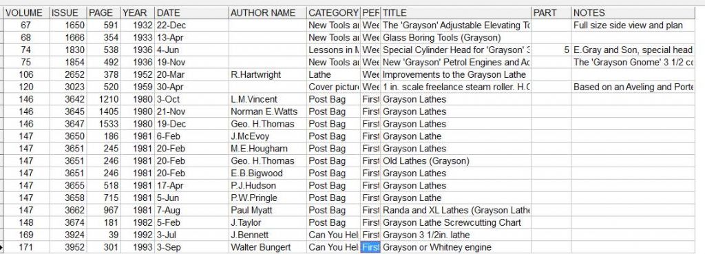
              Edit; There's a letter about grayson lathes in MEW 22 plus the following in ME:

              grayson.jpg

              Edited By Neil Wyatt on 23/02/2016 21:21:16

              #226630
              dave george 1
              Participant
                @davegeorge1

                thanks for your comments guys, neil where have you seen these photos ???

                on tonys site http://www.lathes.co.uk/grayson/index.html it shows the back of tailstock like a small

                long t bar,which i presume moves it forward and backwards or lock it in place,but if the square bolt

                was taken away,the tailstock would lose it setting everytime you slacken the bolt to move the tailstock,

                i just cant get my head around it,if you did some tapered turning you would have to remove the square bolt

                then tighten up with the bolt that holds it onto the lathe bed ???

                i did see a grayson lathe on a auction site,and i sent the guy a message about the tailstock and this is what he said to me

                the usual LH thread & the anti-turn pin/grub screw is through the top. Nothing else comes apart, the only adjustment on it the hex screw for holding it down

                im confuse more to this as it has no thread anywhere apart from the two bolt holes

                #226648
                Ajohnw
                Participant
                  @ajohnw51620

                  Looking at the pictures on Lathes co there are 2 types of tailstock. One with one bolt that holds everything together and holds the tails stock down the other has 2. I assume one to hold down and the other to hold the assembly together.

                  The dowels at each side orientate the axis one way and the other single one sets it level. There is no side adjustment and it doesn't really matter that one set up uses one bolt as when things are tightened down the dowels will align it all again.

                  Looks like you have 2 holes in one shot. The hole in between the 3 dowels will be the one to hold the assembly together I suspect. Just make sure it's all nice and clean before assembling it.

                  Aligning a tailstock very accurately is such a pain I for one never ever offset it once it's set up. Actually when it's within thous I use a morse reamer to true it up exactly and then leave it all alone.

                  John

                  #226671
                  John Fielding
                  Participant
                    @johnfielding34086

                    tailstock alignment 002.jpg

                    Here are some pictures of the tailstock from old Grayson 3 1/2" lathe. The body is split in two and three dowels fit in semi-circular slots. The side dowels allow movement from side to side as when off setting to turn tapers. The rear dowel is removed when this is done. This rear dowel sets the correct axial setting for parallel turning.

                    The large bolt clamps the tailstock to the bed and the bolt underneath clamps the two halves of the body together. On my Grayson tailstock the dowels appear to be 1/4" brass rods, never had to take it apart so not sure if they were made like this.

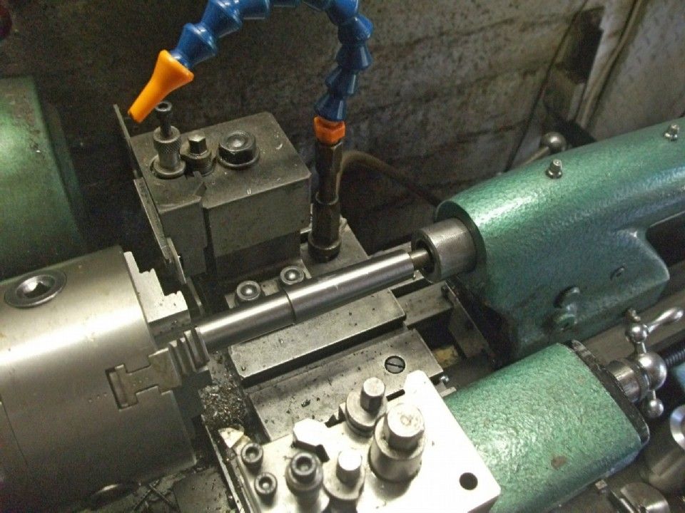
                    To align the headstock a 2MT test bar is used to get the headstock and tailstock in correct alignment. I have shown this being done on my Myford S7 as the Grayson is no longer used. This method is simpler than messing around with a DTI. On the S7 simply slacken off the clamping bolts and adjusting screws and slide the tailstock along the bed until the 2MT is firmly in the tailstock barrel and then nip up the screws.

                    tailstock alignment 001.jpg

                    tailstock alignment.jpg

                    Incidentally I discovered that the Grayson 3 1/2" lathe was the basic design for the Myford ML7.  The headstock spindle has exactly the same register and thread as the ML7 so when I acquired my Super 7 the chucks etc all fitted perfectly.  Seems Myford must have copied this design?


                    Edited By John Fielding on 24/02/2016 09:07:03

                    Edited By John Fielding on 24/02/2016 09:14:28

                    #226674
                    Neil Wyatt
                    Moderator
                      @neilwyatt
                      Posted by dave george 1 on 23/02/2016 21:39:29:

                      thanks for your comments guys, neil where have you seen these photos ???

                      I can't remember but it was probably in one of the letters on that list.

                      #226758
                      dave george 1
                      Participant
                        @davegeorge1

                        thanks for the heads up comment john

                        i think i know what you saying

                        basicly the tailstock should be already true in-line with the headstock

                        if you want to do tapering,remove the bolt that holds the top and bottom of tailstock,then remove the back pin/dowel

                        offset the taper you need,then nip it up using the bolt that clamps it to the lathe bed,when you finished tapering,undo the clamping bolt,put the back pin/dowel back in,then put the other bolt that holds them together back in,and off you go with parallel turning

                        is this correct ??

                        sorry for sounding like a numnut

                        @ neil i only recieved this lathe december that gone,so it couldnt have been me

                        also do you think i should create a thread,about this project that im doing, like a before and after

                        i got a few photo's of various stages,using electrolisis bath,polishing all the bright stuff,like ball handles,handwheel on tailstock etc

                        thanks

                        #226887
                        John Fielding
                        Participant
                          @johnfielding34086

                          Hi Dave George 1,

                          On the Grayson 3 1/2" lathe the headstock is different to the later ML7. On the ML7 the bed top guides are carried on to the head stock mounting area. So the two parts (headstock and tailstock) use the same parallel guides for alignment and are machined in one operation to ensure accuracy.

                          However, on the Grayson the headstock doesn't work the same way. There are 4 bolts that clamp the headstock to the bed extension and a pivot bolt which the headstock can rotate on. When the lathe is assembled the tailstock is the reference point and the headstock is swivelled on the pivot bolt to align the two. Hence, the simplest method is the one I described with the Morse taper test bar . In fact a double ended 2MT test bar is the best method, this plugs into both the headstock spindle and the tailstock and then the headstock bolts are nipped up.

                          I hope that makes it clearer?

                          #226896
                          Michael Gilligan
                          Participant
                            @michaelgilligan61133
                            Posted by dave george 1 on 24/02/2016 19:34:27:

                            … basicly the tailstock should be already true in-line with the headstock

                            if you want to do tapering,remove the bolt that holds the top and bottom of tailstock,then remove the back pin/dowel, offset the taper you need,then nip it up using the bolt that clamps it to the lathe bed,when you finished tapering,undo the clamping bolt,put the back pin/dowel back in,then put the other bolt that holds them together back in,and off you go with parallel turning

                            is this correct ??

                            .

                            That's how I see it

                            … and, assuming they made 'em properly [and you have a matched set of components], it looks like a thoroughly good system.

                            MichaelG.

                            #227015
                            John Fielding
                            Participant
                              @johnfielding34086

                              Hi Dave,

                              Almost but the clamping bolt that holds the two parts together is slackened after the main big clamping bolt and then the rear dowel is pulled out. Then offset the tailstock by sliding it sideways and nip up the bottom bolt and then the main bed clamping bolt.

                              The tailstock parallel slide is a very good fit inside the top shears so it has true alignment with the bed. You will notice that the headstock sits on a flat surface so it can rotate on the pivot bolt. Unlike the ML7 and S7 which has a similar arrangement to the tailstock. Also on the ML7R / S7 there are pusher screws at the headstock end to align the headstock by a tiny amount. These screws are the same ones as the tailstock uses for offsetting.

                              There is one weakness on the Grayson tailstock which is the barrel locking screw. This often breaks the casting and it is very difficult to weld the cast iron pieces back together. Mine has this broken part and I have never bothered to get it repaired as the S7 came along at the right price.

                              On early ML7 lathes the bed was different to the later ML7R and the Super 7. When Myford brought out the Super 7 they scrapped the early bed design and the ML7R and the Super 7 used the new bed design. It has wider top shears to better cope with the higher cutting loads. Also they eliminated the internal bed slideways, that is why the internal slideways on the later versions have a gap between the internal slides and the bed top shear, it was redundant but they used up the earlier castings until new ones were introduced.

                              There wasn't much difference between the ML7R and the Super 7, the Super 7 was a rich mans version and it had the countershaft clutch, better vernier dials, a longer cross slide and a few other twiddly bits which the cheaper ML7R didn't get. By standardising on parts you can retrofit a ML7R to Super 7 specifications quite easily. The main difference is the headstock design. The Super 7 has the newer spindle with the taper bronze front bush and the two angular contact rear ball bearings to control end float. In the end the ML7R and the Super 7 became almost the same machine and the cost of the ML7R became too high as for not much extra you could buy the S7 version, so Myford dropped the ML7R and continued with the S7 version.

                              On my Grayson I made a long cross slide as per the Super 7 by hacking it out of a piece of steel with my (then) new vertical milling machine. I bought the new cross slide handle and nut assy from Myford and it made a big difference to working on the lathe.

                              On my Grayson the headstock is missing. I was going to make new front and rear bearings as per the S7 and sent it to a local company to do the machining. After a few months of not hearing anything from them I found out that they had folded and the liquidators had come in a cleaned out all the stuff, including my partially modified headstock and the chuck backplate from a new 4-jaw chuck I had loaned them as a gauge to cut the front register and thread. So my Grayson is sans headstock and the 4-jaw chuck is minus its backplate Seems it was sold for scrap to raise some funds. I still have all the other bits but without a headstock it is just quietly gathering dust.


                              Edited By John Fielding on 26/02/2016 08:12:19

                              #227044
                              dave george 1
                              Participant
                                @davegeorge1

                                Very intresting information there john,much appriciated. I did notice about the clamping screw that clamps the barrel dont hold like it should do,and i thought about making a thin shim sleeve to go over the barrel but this might hinder it. Luckyly mine is still intact and not broken. Ive have been thinking about getting a fresh cross slide as mine is broken on the t slots at the back and wondered if a myford 7 would do. I will upload more photos when i get on main pc later. I dont suppose you live anywhere near burnley lancashire,(i dont mind travelling a few miles ) maybe i could buy whats left of the grayson lathe you have

                                #227053
                                John Fielding
                                Participant
                                  @johnfielding34086

                                  Hi Dave,

                                  Unfortunately I live a bit further than Burnley these days. I live on the tip of Africa near the sea port of Durban so it is a bit of a haul. A pity really as the old Grayson is just sitting here and I would be happy to pass it onto someone who could do something with it. To ship it overseas would cost the proverbial arm and 2 legs!

                                  #227054
                                  Les Jones 1
                                  Participant
                                    @lesjones1

                                    Hi John,
                                    I used to know a John Fielding many years ago. Did you live in the Liverpool area in the 1970s ? and does "FPH" mean anything to you ?

                                    Les.

                                    #227056
                                    John Fielding
                                    Participant
                                      @johnfielding34086

                                      Is that you FUB?

                                      #227057
                                      Les Jones 1
                                      Participant
                                        @lesjones1

                                        Hi John,
                                        Yes, still in the Liverpool area. Aughton near Ormskirk. Not doing much radio these days. I still have some of the metal from the antenna tower you climbed just after I finished it and BEFORE it was bolted to the base. After I retired I bought a better lathe than the one I had when I knew you. I also bought a Seig X3 milling machine.

                                        Les

                                        #227059
                                        John Fielding
                                        Participant
                                          @johnfielding34086

                                          Hi Les,

                                          Please drop me an email @

                                          johnf (at) futurenet (dot) co (dot) za

                                          and we take this off post.

                                          #227060
                                          dave george 1
                                          Participant
                                            @davegeorge1

                                            I suppose its a bit of a drive to africa,a shame though as i would of had it. Looked into shipping and a rough quote i got was R1495 which comes to about ?68.odd pence
                                            I will upload some more pics after to show the progress of the lath

                                            #227062
                                            dave george 1
                                            Participant
                                              @davegeorge1

                                              Dang phone playing up 68 pounds and odd pence

                                              #227508
                                              dave george 1
                                              Participant
                                                @davegeorge1

                                                ive put some more pictures in my album

                                                this is what lathe looked like before i started

                                                20151109_130526.jpg

                                                made a electrolisis bath using washing soda and water

                                                24 hours.jpg

                                                this is after 24 hours

                                                this is the cross slide and a damaged t-slot all after a quick scrape

                                                20151210_154043.jpg

                                                this is after a week

                                                20151211_135732.jpg

                                                a jet wash and a scrape here and there

                                                20151211_153020.jpg

                                                all the bright work before polishig

                                                20151218_142416.jpg

                                                this is after polishing using a dremel rotary tool

                                                20160119_143510.jpg

                                                20160119_143524.jpg

                                                the lathe has a coat of zinc phosphate primer im gonna give it another coat then paint it

                                                all comments welcomed

                                                #241973
                                                Micky T
                                                Participant
                                                  @mickyt

                                                  hi ive just purchased a grayson lathe. i was wondering if you had any photos of the head stock spindle broken down. i'm about to strip mine to ensure there isn't too much wear and maybe look at replacing the bearings if required.

                                                  #242010
                                                  dave george 1
                                                  Participant
                                                    @davegeorge1

                                                    ive uploaded more pictures of the spindle,not much to comment on it,as theres only the spindle and two

                                                    split bronze bearing,ive left mine in the headstock,it looked hard to get out without damaging them.

                                                    never noticed any play on the spindle,the bearing dont look too badly scored and no deep scratches.

                                                    when i separated the spindle from headstock i measured the diameter of it where it was in the bearings and

                                                    where flatbelt pulley is and the bullwheel

                                                    the measurement of the spindle is 1.125",and the measurement of my spindle are

                                                    nose end (front) is 1.122",the middle where bull gear and pulley is 1.123" and the back where gear train is

                                                    1.123"

                                                    the measurement that you see on the pictures was in mm (as i didnt have a imperial mic at the time)

                                                    20151119_141505.jpg

                                                    20151119_141528.jpg

                                                    20151119_141546.jpg

                                                    20151119_141558.jpg

                                                    20151119_155934.jpg

                                                    20151119_155940.jpg

                                                    20151119_160033.jpg

                                                    20151119_160046.jpg

                                                    i hope this helps

                                                    #242049
                                                    Micky T
                                                    Participant
                                                      @mickyt

                                                      Thank you that helps a lot. At least I know there's nothing complicated in there. This is my first lathe so I'm looking forward to creating lots of swarf. Thanks once again.

                                                    Viewing 25 posts - 1 through 25 (of 35 total)
                                                    • Please log in to reply to this topic. Registering is free and easy using the links on the menu at the top of this page.

                                                    Advert

                                                    Latest Replies

                                                    Home Forums Manual machine tools Topics

                                                    Viewing 25 topics - 1 through 25 (of 25 total)
                                                    Viewing 25 topics - 1 through 25 (of 25 total)

                                                    View full reply list.

                                                    Advert

                                                    Newsletter Sign-up