Flying Bridgeport, where to start!? lots of questions.

Advert

Flying Bridgeport, where to start!? lots of questions.

Home Forums Beginners questions Flying Bridgeport, where to start!? lots of questions.

Viewing 25 posts - 1 through 25 (of 28 total)
  • Author
    Posts
  • #111649
    jason spencer
    Participant
      @jasonspencer41535

      http://s101.beta.photobucket.com/user/jason61c/media/photo-4_zpsb989ff09.jpg.html

       photo photo-3_zpsb351b3c3.jpg

      http://s101.beta.photobucket.com/user/jason61c/media/photo-4_zpsb989ff09.jpg.html

       photo photo-4_zpsb989ff09.jpg

       photo photo-5_zpsefbb8cb0.jpg

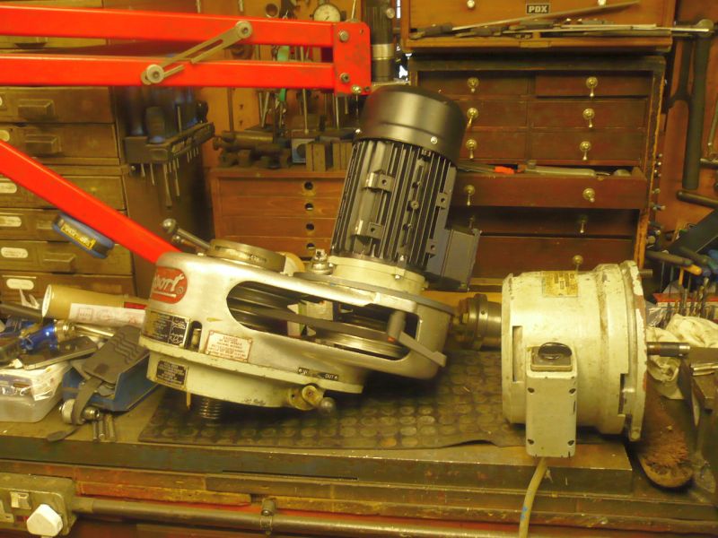
      Pictures speak a thousand words. A great morning, a lot less hassle than I thought and takes up less space too.

      My mill is now in position, I've started to give her a clean as its sat unused for 15years.

      So far, given a slight clean, worked out the one shot lube system.

      So my list of questions are as follows.

      Should I repaint it? or is it not worth it?

      Slides are strangley free in all axis, anything else I should do before using?

      Its a 2hp 380-440v motor, I've got headaches working out what to do to power her. Suggestions welcome!? Its also got a powered slide and coolant pump.

      I need to wire her back up, where can I get a few replacement switches etc from?

      Any way to date her? Its got a door on the side of the base, with a 4 digit number, the head has 5 digits. I do know a bit of history for the machine.

      Does it need bolting down?

      Tooling, new vice or old? Would a r8 er32 chuck be a sensible idea?

      Moving Knee- makes a slight grumble going up and down, doesn't seem like an issue to me, should it be smooth as a babies bottom?


      Really sorry for all the questions! Bit of an excited boy here


      Edited By jason spencer on 10/02/2013 22:21:15

      Edited By jason spencer on 10/02/2013 22:21:51

      Edited By jason spencer on 10/02/2013 22:22:56

      Edited By jason spencer on 10/02/2013 22:23:27

      Edited By jason spencer on 10/02/2013 22:24:32

      Edited By jason spencer on 10/02/2013 22:24:53

      Advert
      #6573
      jason spencer
      Participant
        @jasonspencer41535

        New mill owner – old mill.

        #111650
        John Stevenson 1
        Participant
          @johnstevenson1

          Don't paint it – use it.

          Last two numbers on the door are the year. It's an old one 1968 ? because it has the older mechanical power feed which IMHO is far better than the electronic type that used to masquerade as a one bar electric fire

          They will run off a single phase inverter, wiring is on the terminal block, wire for low voltage. You have the step speed head which with an inverter is a far, far better piece of gear than the varispeed head.

          Don't bother bolting down, not worth it, just make certain it doesn't rock.

          Knee's do suffer on these because of the over balance weight, get plenty of oil into it and work it up and down.

          #111651
          jason spencer
          Participant
            @jasonspencer41535

            Yep, 1968, also found the plate on the inside of the door that has the month also. Think i'm just going to give her a good clean and leave it. It came via carlin motorsport who themselves purchased the equipment from brabhams f1 when they bought the redundant equipment after they ceased trading. I guess it might have some F1 swarf in it!

            The knee isn't stiff, just a little grumbly.

            I was hoping it could be wired for 240v 3 phase as the inverters are cheaper however I can't see that it can be? the terminal block inside the switch cover is a little on the confusing side.

            Regarding the power feed, it is an earlier one(6f?) however I seem to be missing the speed change handle…… Another thing on the list or would I be dreaming If I thought I could get hold of one?

            #111653
            John Stevenson 1
            Participant
              @johnstevenson1

              Yes they can be provided it's not the rare two speed. By two speed that means it has 5 positions on the switch.

              If it has 3 positions then it can run OK off an inverter. If all else fails it's a doddle to bung a decent 3hp motor on it instead of those stupid 60 Hz yankee toasers.

              I can ask and see if the guy I deal with, midlands Bridgy engineer has any spares for the 6F unit?

              BTW nice pic of the delivery but this is a flying Beaver <BG> wink

              #111654
              jason spencer
              Participant
                @jasonspencer41535

                ive 5 positions on the switch!! It'd be good if you could ask about spares. Where would be the best place to source a sutible motor?

                #111655
                John Stevenson 1
                Participant
                  @johnstevenson1

                  In which case bung the motor on Ebay and use the money to get a decent motor.

                  Advertise it as very rare two speed motor, you can run these from home but you need either a rotary converter [ noisy and expensive ] or a transwave unit which is an even worse cludge than the Bridgeport toaster.

                  I can sort you a motor out if you want with the right plate and shaft, just like the one in the picture if you want.

                  I got this one to fit onto my POS bridgy instead of the clatterbox varispeed unit but since decided that I'm fed up of having to shut the doors on a windy day so the cutter isn't blown off course and ordered a larger mill so no point trying to improve this licorice POS.

                  #111657
                  jason spencer
                  Participant
                    @jasonspencer41535

                    Yes please, can you pm me details etc? Nice beaver by the way

                    #111658
                    _Paul_
                    Participant
                      @_paul_

                      Jason apologies for the post hijack.

                      John do you intend to get rid of that step head? if so could you send me a PM please.

                      Jason they are a bugger to paint without stripping down.

                      ER32 chuck works great BTW bought mine from a chap in china via Ebay less than £20 with shipping.

                      Paul

                      #111667
                      MattK
                      Participant
                        @mattk47317

                        Hi Jason,

                        I have a BP of a similar vintage to yours. It has a smaller motor fitted which is only 1HP on the J Head but it is nearly new and OK for me. I also have the same table feed as yours. I think the 6F feed is the electronic one that came a little later. I fitted two 1HP VFDs to mine and finished getting it all working yesterday. I have remote start/stop/reverse and a speed pot on the head and a speed controller pot now on the table feed. One of the things I like about this machine is that the only electronics are on the VFDs I've fitted.

                        I was trying to control costs a bit so I just bought a few R8 collets and cutters to match and so far happy with them. I would like to get an ER chuck later though. I have not bolted mine down yet, in fact it is still on scaffold pipe rollers as I am still deciding about final position in the workshop.

                        If you have not already got it, a PDF of the manual is easy to get hold of on the web. Worth getting hold of.

                        Personally I would look for an older vice as I think your money may go further, but it is the usual thing about wear etc. Mine came with a big Jones & Shipman and somebody had drilled it and pinned it to the table which is OK I guess as it is simple and accurate to relocate.

                        Milling on this machine is a real pleasure compared to my efforts on the slide on my Myford S7. I think the extra stiffness of the BP makes life easier.

                        #111672
                        NJH
                        Participant
                          @njh

                          Nice one Jason!

                          The only (useful?) comment I have to make is on your query of painting. To do so will not improve the performance smiley but may make you feel even better about your new "toy" and will, more usefully, ensure that you have a really good look around the machine. If you are going to paint it do it now because once you get to use it and the novelty wears off you will never then get round to it.

                          (Now then where do you live – I've a couple of little bits that need machining……………….)

                          Cheers

                          Norman


                          Edited By NJH on 11/02/2013 10:29:33

                          #111703
                          Bazyle
                          Participant
                            @bazyle

                            Before painting just go round with T-cut like with an old car and see if that meets your requirements for bling. It does get old oil staining off but I'd like ideas on a cheaper product for that.

                            #111816
                            Pete
                            Participant
                              @pete41194

                              I can't and won't comment about the electrical since there's not much in common with our two countries and anything electrical. But if you can? Then most definately use a VFD.

                              I bought my mill new, but I see nothing I'd change for methods today, and I think this is more than a bit important. These types of mills are a pretty simple collection of parts that break down into the major sub assemblys fairly easy. Given your mills past history, length of storage without use, etc. If it were me? I'd blow it apart using an engine hoist, and do a full clean and adjust. You will be amazed at just what you find for swarf packed away into areas you'd swear it shouldn't be possible to reach. You'll also have a mixture of old congealed oil, machine wear particals, cutting fluid, and that swarf, along with any dust and dirt it's managed to pick up while not being used. None of that will help with it's future accuracy or smoothness of operaion.

                              After stripping the table, Y axis assembly, feed screws. Then the knee lifts out straight up past the knee dovetail. The motor, head, and ram should be removed to allow clearence for the knee as it slides up the dovetail. Remember to slack the knees gib right off or remove it before removing the knee. After doing that cleaning, you can then verify that the one shot lube system is correctly metering oil to everywhere it should as you put the mill back togeather. It's also the time to check everything for needed repairs or excess wear. And make the nessisary feed screw / nut / gib adjustments. A couple of days spent doing this and you'll be amazed at just how smooth it now operates. Probably including that knee. It sounds like something is jamming it up. And depending on just what design you have for gibs? You do NOT want to break a tapered gib in that knee. It is a very long, tough to do vergeing on the impossible job.

                              I also wouldn't remove the feed nuts from there factory aligned position. I would make sure the bolts holding them in place were very tight. And I'd then just clean them in place using something like a spray contact cleaner.

                              New verses old vice? That depends. How old is old, and to state the obvious, condition is everything. A lot of the older vice designs didn't use something like the Kurt style of vises do where the moving jaw is also pulled down as it fully tightens up. Even with that, they can still need a bit of help tapping the work down with a dead blow as the vise tightens at times. Old enough and with enough wear? It may only be worth scrap value.

                              ER collets and chucks? I've got an ER-40 setup on mine. Probably the ER-40 is a bit too large for a R-8 taper mill though. But the internal R-8 collets do of course get the cutting tools positioned a lot closer to the mills lower spindle bearing. It depends I guess on just how hard you figure you'll push that mill towards taking maximum cuts.

                              There's one book I highly recommend if you don't have a lot of experience with these types of mills. "Turret Mill Operation". Mine isn't handy right now, but maybe a google search will turn up the author and ISBN.

                              Pete

                              #111870
                              jason spencer
                              Participant
                                @jasonspencer41535

                                Thanks for all the info so far folks.

                                All the gearing in my powered travel seems to be in good condtion however I need to locate a speed selector handle for it if anyone can help?

                                My main issue is deciding how to power it. As all the motors are 440 3ph it means a 'smart inverter' that'll run them all is £750, I just can't stomach that really. My head motor is the duel speed type 380-440v.

                                Or I run an inverter for the head then a second for the pump and powered slide at about £340 for the head and £250 for the second. I do like the idea of using the machines original power input and everything working as it should.

                                Any other ideas?

                                #111872
                                MattK
                                Participant
                                  @mattk47317

                                  Hi Jason,

                                  I can see your dilemma. For what its worth I would be surprised if the table drive motor cannot be rewired to be 230V. I did mine OK although there are no links in the terminal box, there is a connector block. Can you read the motor plate as this will indicate whether it is dual voltage?

                                  Mine does not have a suds pump so cannot comment on that. I also think that if you can match the voltages from the head motor and the suds pump, you could drive them both off the same Vfd as long as the bigger motor was running when the smaller one was. I have seen this somewhere on a Harrison lathe conversion and I also note that Teco mention running more than one motor in their online manual but not in the printed one you get in the box.

                                  Probably the cheapest way to get it all going is to use a static or rotary converter to power the whole machine. Where you will lose out doing it this way is the variable speed which you can just dial up which I think is great on the J pulley head.

                                  #111875
                                  jason spencer
                                  Participant
                                    @jasonspencer41535

                                    Yes, its tricky, the duel speed motor with the belt options will offer everything I need. I did call drives direct but didn't find them overly helpful as I did ask about just using the one converter and having the head running before powering the table/suds pump etc but they were pushing the idea of the £750 jobbie. Maybe a rotary phase converter is the best option?

                                    #111877
                                    jason spencer
                                    Participant
                                      @jasonspencer41535
                                      Posted by MattK on 12/02/2013 15:26:26:

                                      Hi Jason,

                                      I can see your dilemma. For what its worth I would be surprised if the table drive motor cannot be rewired to be 230V. I did mine OK although there are no links in the terminal box, there is a connector block. Can you read the motor plate as this will indicate whether it is dual voltage?

                                      Mine does not have a suds pump so cannot comment on that. I also think that if you can match the voltages from the head motor and the suds pump, you could drive them both off the same Vfd as long as the bigger motor was running when the smaller one was. I have seen this somewhere on a Harrison lathe conversion and I also note that Teco mention running more than one motor in their online manual but not in the printed one you get in the box.

                                      Probably the cheapest way to get it all going is to use a static or rotary converter to power the whole machine. Where you will lose out doing it this way is the variable speed which you can just dial up which I think is great on the J pulley head.

                                      Just to add, I can't make out the motor plate, i'll try some sort of rubbing on it. A nice surprise was to find the original leaflet folded up inside the wiring box

                                      #111928
                                      jason spencer
                                      Participant
                                        @jasonspencer41535

                                        Well a slight result

                                        I've taken the covers off the pump and slide motor, both had the wiring sheets installed when new(some 45ish years ago), The pump can be wired for 220-240v 3 phase and the slide motor has a definate 220 just visible on the motor next to a /, is is 1/8hp, wiring details for 'low voltage' too.

                                        So a £350 inverter to run the head and a used inverter off ebay for £80ish to run the 2 small pumps, seem like a good plan?

                                        My only other thought/question is where does the power for the quill feed come from, just geardriven from the head motor? I can't work out the diagrams on the factory fitted swtich panel.

                                        #111932
                                        KWIL
                                        Participant
                                          @kwil

                                          Jason,

                                          The drive for the quill down feed (or up) is derived mechanically by gears from the spindle drive, which are engaged by the control in the centre of the slow feed wheel. I also use the  inverter to power the suds on both the Bridgeport and my M300 which I converted some time ago. The suds pump is so small a power drain as not to affect the inverters ability to power the spindle.

                                          Edited By KWIL on 12/02/2013 22:57:33

                                          #111953
                                          jason spencer
                                          Participant
                                            @jasonspencer41535

                                            I thougth it would be, I just couldn't work out what the 4 swiches do on the front control panel. Managed to get a small inverter for £65 off ebay so just the main source of power to think about now…

                                            #111994
                                            MattK
                                            Participant
                                              @mattk47317

                                              Jason,

                                              Apologies if you already know this…

                                              I am assuming your control box on the side of the column has a number of three phase contactors. These are normally actuated by the switches on the front control panel. With vfd drives the contactors become redundant and the switches can be used as direct inputs to the inverters. I don't have the switch panel like yours so cannot guess exactly what the configuration is but that's how mine is done. I wired up a bit of functionality at a time and had no problems. Now just got to figure out how to get the emergency stop to work on both inverters but think it will be no problem.

                                              #112030
                                              jason spencer
                                              Participant
                                                @jasonspencer41535

                                                Hi matt

                                                could you send me pics/details of how you wired yours up?

                                                If I had a 3 phase lathe one of the expensive plug and play drives would make sense, well it'd be easy!

                                                #112036
                                                KWIL
                                                Participant
                                                  @kwil

                                                  Inverters have a facility to apply a stop signal from an external device. On that part of the inverter's inputs where you can command a Run, Fwd or Reverse there is also a STOP command.

                                                  The problem if you want to keep the full functions such as stop in the event of mains failure, stop if the chuck or any other "alarmed" guard function to work, it is rather more than just supplying the motor with 3 phase from an inverter.

                                                  #112037
                                                  KWIL
                                                  Participant
                                                    @kwil

                                                    If you would like to see how it can be done, look at MEW 154 in the digital copies.

                                                    #112113
                                                    MattK
                                                    Participant
                                                      @mattk47317

                                                      Hi Jason,

                                                      I will draw a diagram up but it is very trivial in my case. The switch for the head which has stop, run and reverse settings goes direct to the inputs on the inverter for the head. I also have a remote potentiometer with the three inputs also going direct to the inverter. There is Live and neutral power and three outputs direct to the motor. If the motor rotates in the opposite direction this can be remedied by either changing two output phases around or setting a reverse bit on the inverter. The table drive has a switch to run it (otherwise it would be on all the time), power and the outputs again to the motor.

                                                      Everything should be earthed for safety. I will also wire in the emergency stop but only in the simple case of putting the normally closed switch to the inverter.

                                                      As KWIL states a power outage situation is not covered by this solution.

                                                    Viewing 25 posts - 1 through 25 (of 28 total)
                                                    • Please log in to reply to this topic. Registering is free and easy using the links on the menu at the top of this page.

                                                    Advert

                                                    Latest Replies

                                                    Home Forums Beginners questions Topics

                                                    Viewing 25 topics - 1 through 25 (of 25 total)
                                                    Viewing 25 topics - 1 through 25 (of 25 total)

                                                    View full reply list.

                                                    Advert

                                                    Newsletter Sign-up