Drive milling spindle but allowing vertical movement (Myford)

Advert

Drive milling spindle but allowing vertical movement (Myford)

Home Forums Workshop Tools and Tooling Drive milling spindle but allowing vertical movement (Myford)

Viewing 11 posts - 1 through 11 (of 11 total)
  • Author
    Posts
  • #19070
    Noel Rieusset
    Participant
      @noelrieusset48142
      Advert
      #371024
      Noel Rieusset
      Participant
        @noelrieusset48142

        Hello Everybody,

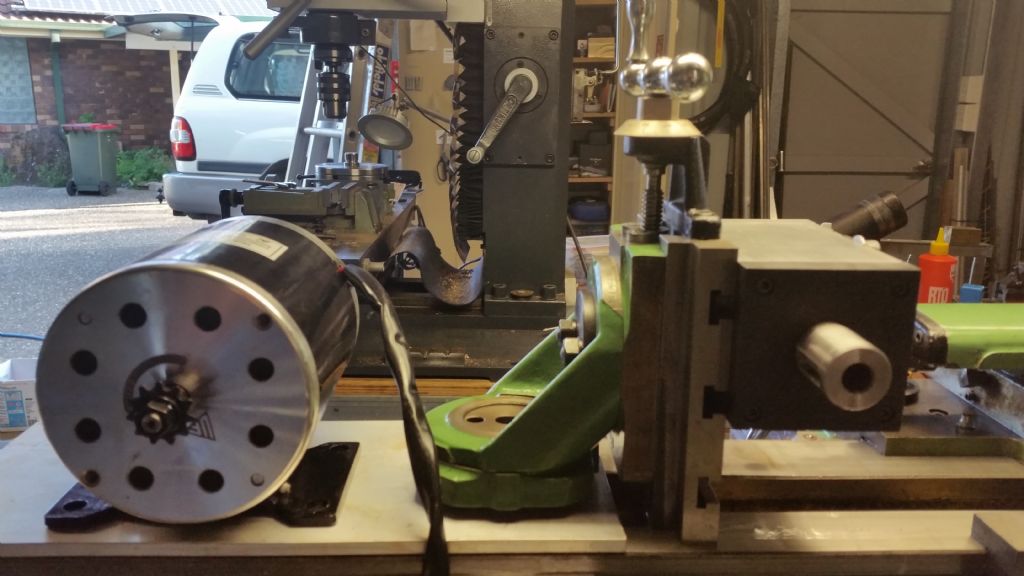
        I have am in the process of building a Milling Spindle for the Vertical Slide of my Myford Super 7.

        I have completed the spindle with two adjustable bearings on the cutting end, with two plain bearings on the pulley end. It has a No. 2 Morse taper to accept tooling.

        Milling Spindle for Myford

        I am driving it with a 500 Watt E cycle motor, with variable speed controller, it runs just great.

        The set up shown which will be mounted on the cross slide has a center distance between the shafts of 250 mm.

        Can anybody help me with an idea of driving the spindle with the motor…

        But….

        Allowing the vertical slide to be adjusted up and down.

        Other than adjusting the centre distance with every height adjustment.

        I put it to the brains trust.

        #371025
        JasonB
        Moderator
          @jasonb

          That seems a big motor.

          A lot of designs have the motor and spindle as one unit that move up and down together so the belt tension stays the same.

          Another option is to have an overhead layshaft and the motor fixed behind the lathe. The long round belting upto the layshaft and back down to the spindle means that any stretch due to spindle movement is a small percentage of the overall length so not worth worrying about.

          If your motor was mounted mid height of the vertical slide the actual change in ctr distance would be small and round rubber belting would more than likely take up the changes, you could always add a jockey wheel to keep tension the same when ctr distance does change if you want to use a toothed or Vee belt.

          Edited By JasonB on 09/09/2018 07:51:26

          #371026
          Bob Stevenson
          Participant
            @bobstevenson13909

            You layout is quite common in clockmaking and is vitually identical to that described by John Wilding in several of his well known clock building books…….. As Jason rightly observes, the spindle is almost of a perfect arc to the motor axes, so raising the motor with a small block etc would probably suffice, especially with round plastic belting as used widely in the clock trades….use the 9mm one with alluminium pulleys to the right 'V' profile….join the belt with a little tension by means of a hot knife blade (you put the knife in the vice, hold belt ends gainst the blade and slide off to make the join!) This sort of plastic belting is very forgiving in the tension dept so not dificult to encompass small(ish) changes of distance between the spindle and motor.

            #371028
            Michael Gilligan
            Participant
              @michaelgilligan61133

              This is how J. Malcolm Wild does it: **LINK**

              http://www.j-m-w.co.uk/tools9.html

              … or you could make a full 'overhead' as seen on ornamental-turning lathes.

              MichaelG.

              #371033
              John Hinkley
              Participant
                @johnhinkley26699

                If you use a toothed belt drive arrangement, perhaps you could introduce a spring-loaded jockey wheel into the system to "take up the slack" as the vertical slide moves up and down?

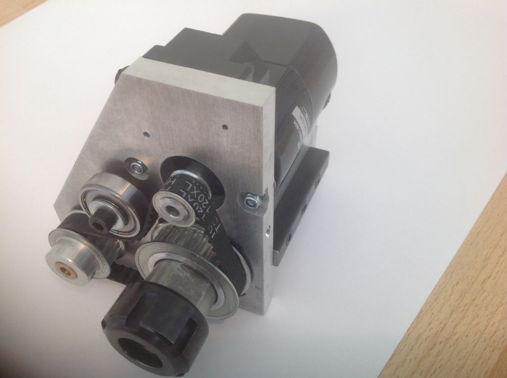
                A bit like I used on my version 1 toolpost spindle:Assembled toolpost spindle.

                The jockey wheel in this instance is just a bearing located in a slot to provide tension to the drive belt, but the priciple is the same, only spring load it.

                John

                P.S. Just a thought: If the length of the drive belt doesn't alter drastically, maybe a continuous round belt would stretch sufficiently to accommodate the slide travel? I don't have any experience of such belting, but someone who has will soon be along to quash that idea!

                #371035
                Neil Wyatt
                Moderator
                  @neilwyatt

                  Mount the motor on a hinged plate and fit a big spring to keep the tension on.

                  When I fitted a half-horse hoover motor to my mini lathe. I just put it on a hinge bit of plywood. 98% of the time that was plenty and when I needed extra grunt I pressed down on the top of the motor

                  Made changing pulleys easy too!

                  Neil

                  #371052
                  Nick Wheeler
                  Participant
                    @nickwheeler

                    millingmotor[1].jpg

                    Pic above is mine. That's £90 worth of ER11 milling spindle, adjustable power supply, clamp and collets. Plus about an hours work to adapt the mini-lathe vertical slide to the WM250 lathe and some mounting holes for the clamp(which can also bolt to the other face). That gives me height adjustment and the capability of drilling at an angle into the workpiece. My intention is to make a clock, didn't want a complex project and didn't have any motor or spindles to make one of the more traditional setups. Which look a real pain to install, setup and use.

                    Here's a quick and dirty trial, indexing by eye off the chuck jaws(I've most of the bits for a stepper motor dividing attachment)

                    makingtestpiece[1].jpg

                    #371055
                    blowlamp
                    Participant
                      @blowlamp

                      If you hadn't been as advanced into the project as you are, I would have suggested you take a look here


                      https://www.ebay.co.uk/itm/400W-48V-Air-Cooled-Spindle-Motor-BLDC-Motor-Controller-Power-Mount-12000rpm-min/263334588965?hash=item3d4ff6f225:glEAAOSwYwJaEsXu


                      Umpteenth EDIT:  ***Can't be arsed with trying to get this website to display the link correctly***

                      Edited By blowlamp on 09/09/2018 12:19:13

                      Edited By blowlamp on 09/09/2018 12:22:23

                      #371057
                      Michael Gilligan
                      Participant
                        @michaelgilligan61133
                        Posted by blowlamp on 09/09/2018 12:11:32:

                        Umpteenth EDIT: ***Can't be arsed with trying to get this website to display the link correctly***

                        .

                        … like this ? **LINK**

                        https://www.ebay.co.uk/itm/400W-48V-Air-Cooled-Spindle-Motor-BLDC-Motor-Controller-Power-Mount-12000rpm-min/263334588965

                        MichaelG.

                        #371059
                        John Haine
                        Participant
                          @johnhaine32865

                          A crude but effective method I've seen somewhere is to mount the motor on a board, one end of which is pivoted somehow on the RH edge of the cross slide. Tension is applied through the motor weight but the board can pivot up and down as the height of the slide varies.

                        Viewing 11 posts - 1 through 11 (of 11 total)
                        • Please log in to reply to this topic. Registering is free and easy using the links on the menu at the top of this page.

                        Advert

                        Latest Replies

                        Viewing 25 topics - 1 through 25 (of 25 total)
                        Viewing 25 topics - 1 through 25 (of 25 total)

                        View full reply list.

                        Advert

                        Newsletter Sign-up