dividing head /indexing

Advert

dividing head /indexing

Home Forums Workshop Tools and Tooling dividing head /indexing

Viewing 25 posts - 51 through 75 (of 77 total)
  • Author
    Posts
  • #266971
    Paul White 3
    Participant
      @paulwhite3

      John S. Thanks for your posting and direction. The thread is interesting in part because it answers a question

      raised when I read recently that your black box failed and you went Linux way. Now I know the story.

      Again many thanks.

      Paul.

      Advert
      #266973
      Hopper
      Participant
        @hopper
        Posted by mark smith 20 on 16/11/2016 14:54:22:

        Hopper interesting ideas.

        heres a piston indexing head!

        **LINK**

        Don't get me started. I have a six inch diameter Cummins piston sitting under my bench that I have been wondering what to do with.

        Really though, when you look at the work involved still, I reckon you are better off to get some 75mm x 16mm BMS flat bar or whatever it takes, cut it up and and screw and dowel it together to make a Harold Hall head from scratch.

        I wish I had the patience to sit down and learn about computer coding, stepper motors and PCB boards etc but I'm afraid it just is not my idea of a fun time for some reason. Whereas wrestling greasy bits of metal is. Go figure.

        Edited By Hopper on 17/11/2016 12:40:33

        #266997
        John Haine
        Participant
          @johnhaine32865

          Paul, the 4059 is a generic CMOS 4000 series part, widely available, probably Maplins have them. The VN10 is just a mosfet, probably it's driving the stepper motor? If so then anyway I'd just buy a complete stepper driver these days, cheap as chips.

          The PLL would use something like a 4046 which is a complete PLL on a chip. It would be set up to take pulses from an encoder on the spindle and synchronise its internal oscillator to N times their frequency, using an external divide by N (such as the 4059). So if you had one pulse per rev from the spindle and N was 1000, the internal oscillator would run at 1000 pulses per rev. Then you can divide that down with another 4059 to drive the stepper that turns the gear blank.

          #267002
          mark smith 20
          Participant
            @marksmith20

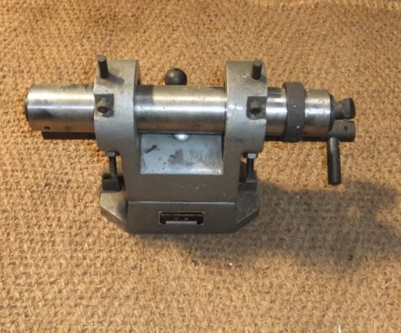
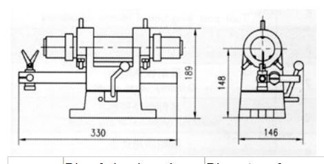
            Well i bought this from GM tools ,i think ill be able to make something usable out of it, if not it may come in for its intended purpose. I think the centre height is just under 6" .

            My bigger mill has a 101/2" wide table but not that long. Thing i like about it is it has a hole built in as well for an arm so i can still do something along the lines of the GHT .

            I think its 5c collets but not sure ,as there was little info and not even sure if its complete . But for 25 quid plus vat /delivery i thought it was worth a punt.

            Any thoughts? Theres one left at G&M if anyones interested.

            Probably same as this only alot cheaper

            http://www.ebay.com/itm/Phase-II-End-Mill-Cutter-Sharpener-Stock-235-001-with-Wood-Case-NICE-/192027340157

            end mill grinding fixture.jpg


            dimensions.jpg

            Edited By mark smith 20 on 17/11/2016 16:47:39

            Edited By mark smith 20 on 17/11/2016 16:54:14

            #267131
            Muzzer
            Participant
              @muzzer
              Posted by Paul White 3 on 17/11/2016 11:09:03:

              The ic's -HEF4059, VN10LM, are the problem units.

              Good god, those FETs are from The Ark. I recall using VN66AF and VN10KM (originally from Siliconix) back in 1979 or possibly 1980. The VN66AFs were one of the first power MOSFETs I came across. You could drive them directly with CMOS (eg 40106 Schmitt trigger buffer). Expensive but so easy to use compared to valves and bipolars.

              I made a simple, portable 2MHz AM RF transmitter receiver using one of these and a linear (audio) power amp. That was before I got my RSBG license G8XCN, so yes, it was illegal but ironically I stopped doing RF stuff once I got licensed. I guess the thrill had gone…

              Without seeing the circuit, I imagine a modern logic level power MOSFET would work fine (better) and cost peanuts, something like this.

              #267138
              Paul White 3
              Participant
                @paulwhite3

                John, many many thanks for a most helpful and informative posting.

                Your comment on the VN10 is spot on, the purpose of its inclusion was lack of output to the stepper driver when

                Brian Thompson first built. the unit.

                The explanation of PLL you gave is most enlightening and produces an alternative for the one part of the project that raised concern in my mind. The concept is clear to me but I lack the know how to set up the circuitry.

                One of Steve Wards objectives in his divider design was for a self contained small unit and that is what I wanted with the hobbing device.

                thanks for your help. Paul.

                #267147
                Paul White 3
                Participant
                  @paulwhite3

                  Muzzer, thanks for your posting. The 80's , oh yes I remember them well (cue for a song).

                  I expected things to have moved on in the world of electronics since 2005 and the circuit function requirement is simple. My ability in this area is monkey see monkey do.

                  Your suggested replacement is noted thanks. How about 2N7000?

                  regards Paul.

                  #267150
                  Muzzer
                  Participant
                    @muzzer

                    It's possible that the 2N7000 may be a close replacement for the VN10KM but the gate threshold voltage looks rather low to be a "logic level" device and could be a problem here. I assumed blindly that it was driving a motor, hence the device I suggested may be way OTT.

                    Is there a schematic to look at? It's not sensible to suggest alternatives without some idea what the application looks like, as I've just illustrated!

                    #267158
                    Paul White 3
                    Participant
                      @paulwhite3

                      Muzzer, thanks for response. The use of the device is to provide input to stepper driver, what John Haine described as, cheap as chips.

                      The only schematic I have is from the MEW article. I'm not sure of the protocol of posting it here, I could E-Mail

                      a copy if you leave me a message with your address.

                      Paul.

                      #267162
                      John Haine
                      Participant
                        @johnhaine32865

                        I've managed to find the article, I actually have that issue! The VN10 LM is just used as an inverter to give a bit more current to drive the stepper moter driver itself. A normal NPN transistor like a 2N3904 with a 1K resistor driving the base from the inverter would be a perfect substtitute or wire the 2 unused gates of the CD4070 with their outputs in parallel, one input on each to ground, the other inputs connected together and to pin 23 of the 4059 would probably work as well.

                        The unit depends on a quadrature encoder with its outputs XORed to double the frequency, you therefore need lots of pulses per rev. Using a PLL one would replace everything from the encoder input to pin 1 of the 4059, I'll have a think about what is needed.

                        To help, what is a typical spindle speed for a hob cutter? That determines some of the characteristics of the PLL design.

                        #267171
                        Paul White 3
                        Participant
                          @paulwhite3

                          John, you have been busy. The cutter speed is 150 RPM. I today ordered a 6oo P/R encoder described as AB two

                          phase. The stepper will be driven by one of your "cheap as chips" TB6600 2/4 phase hybrid motor driver.

                          Your outline is very encouraging.

                          regards Paul.

                          #267185
                          Neil Wyatt
                          Moderator
                            @neilwyatt

                            Next MEW will have a detailed description of making an arduino driven rotary table/dividing head setup with a link to the downloadable code.

                            Neil

                            #267200
                            John Haine
                            Participant
                              @johnhaine32865

                              Will it do hobbing as well?

                              #267230
                              Hopper
                              Participant
                                @hopper
                                Posted by mark smith 20 on 17/11/2016 16:45:26:

                                Well i bought this from GM tools ,i think ill be able to make something usable out of it, if not it may come in for its intended purpose. I think the centre height is just under 6" .

                                end mill grinding fixture.jpg

                                Edited By mark smith 20 on 17/11/2016 16:47:39

                                Edited By mark smith 20 on 17/11/2016 16:54:14

                                That looks like just the ticket. Brilliant. It depends on what you want to use it for, but the quickest way to get it useable might be to make into a direct indexing "spin indexer" by bolting a lathe change gear on one end and a chuck on the other. A 60 tooth gear will give you all the common divisions you might need, 2,3, 4, 5, 6, 10, 12, 15 etc just by using a spring loaded plunger on the teeth. Or a 24T will give you most as well, 2,3,4,6,8,12. If you use a 60T you can then add a worm to GHT specs and get full dividing capacity. One thing you will need is a spindle lock, not sure if that is already built into the unit?

                                #267363
                                Howard Lewis
                                Participant
                                  @howardlewis46836

                                  Coming in late, as usual, if you lack welding facilities, you could fabricate and bolt parts together. (for belt and braces dowel as well to guard against any movement in the future).

                                  You only need to ensure that the faces and bore are square to each other, (first face machined to clean up will act as datum) and machining using as few set ups as possible should do that. The end result may not be concours d'elegance contender, but the test is: Will it do the job?

                                  How you drive it, manual, stepper motor or water wheel; is your choice, depending upon skill/materials available.

                                  College Engineering Supplies used to do a kit for a Rotary table, and sold the Worm and Wheel as a separate item. Presumably, the new owners still do?

                                  FWIW, my Vertex HV6 Rotary table is 90:1 ratio, which would be my choice.

                                  Good Luck with the project.

                                  Howard

                                  #267364
                                  Emgee
                                  Participant
                                    @emgee
                                    Posted by Neil Wyatt on 18/11/2016 18:12:13:

                                    Next MEW will have a detailed description of making an arduino driven rotary table/dividing head setup with a link to the downloadable code…..

                                    If your'e impatient and want a background to an Arduino controlled dividing head or rotary table before the MEW issue is published take a look at the HMEM site article.

                                    Emgee

                                    #267673
                                    mark smith 20
                                    Participant
                                      @marksmith20

                                      Hi I have a question regarding the change gear , can i use a harrison 60T change gear? Im wanting the head to be pretty robust and the harrison gear is alot chunkier than a myford.

                                      Also are these hard to machine as ill need to bore out the hole a bit bigger and possibly face turn to suit as they are 1" thick according to the link. They are 14dp which for a 60t gear is what in diameter terms ???

                                      Such as **LINK**

                                      Also anyone know if Chinese mn65 steel is easy to weld?

                                      Thanks

                                      #267678
                                      Anonymous

                                        Assuming a standard tooth depth spur gear the OD will be tooth count plus 2, all divided by the DP.

                                        Andrew

                                        #267688
                                        mark smith 20
                                        Participant
                                          @marksmith20

                                          Thanks Andrew,

                                          so around 4.4286"?

                                          Ive received the above contraption ,i going to have to do some rethinking about how to possibly do something with it.

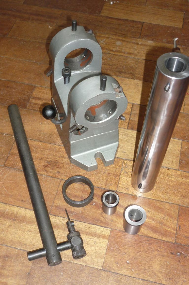
                                          The spindle (44.5mm diameter) is quite nice but is straight bored not 5c as i thought. It came with two collets in either end  rough 18mm and 22mm.. they fit very nicely .

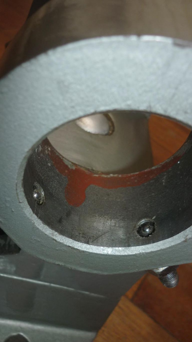
                                          The all spindle rides in the large casting bore on 3 equally spaced adjustable screws with what looks like round bearing balls on the end.  I think i may have to get rid of these and put a bearing of some sort in either end and then go from there.

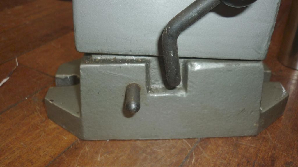
                                          The casting top half and lower half do not sit properly and are wobbling all over the place. The lever which i assume is to lock the two parts together seems to be doing nothing and i cant seem to see how to get the two parts seperated.

                                          I was thinking i may have to have the two bits welded together.

                                          There is several sheets of instructions which are spotted all over with mildew so hard to read .

                                          Edited By mark smith 20 on 21/11/2016 11:50:56


                                          p1300299.jpg


                                          p1300301.jpg

                                          p1300302.jpg

                                          Edited By mark smith 20 on 21/11/2016 12:02:14

                                          #267696
                                          Hopper
                                          Participant
                                            @hopper

                                            MMM, by the time you look at welding the base together, with subsequent distortion issues, and cast iron welding being a bit tricky, and then line bore the holes to install bushings, and is that spindle hardened or suitable to remodel to fit your lathe chuck, it almost might be easier to build Harold Hall's dividing head out of some square pieces of flat plate bolted together.

                                            On the other hand, if you can bolt and dowel the base together and put a super thin pair of bushings in place of those three screws each end, or simply turn up a new spindle with larger OD to run straight in the existing body holes you will be most of the way there with what you already have got.

                                            Not sure about the Harrison gear. One inch thick is a lot more chunky than you need. And 14DP, you will have to calculate the pitch of the Acme thread to match it, and then then change gear compound train to cut it. Also, to get the right helix angle on the worm, it will have to be fairly large diameter.

                                            Whereas, the standard Myford 20DP has been done plenty of times before with all the info readily available. Also the added diameter of the 14DP gear, circa 4 inches vs circa 3 inches for the 20DP, means the worm mechanism will be sticking out that much further from the spindle and body, which means it will be more in the way in use.

                                            Also the wormwheel simply moves the spindle position; it is not used to transmit power so there is no gain in a bigger chunkier gear.

                                            But hard to say without anything in your pics to give scale. Maybe a Harrison gear would be more in proportion to what you have already? Another possibility might be a 14DP gear from a Drummond lathe. They are only 5/8" wide so maybe a bit more suitable? They, like most but not all changegears are cast iron.

                                            #267707
                                            Bazyle
                                            Participant
                                              @bazyle
                                              Posted by Hopper on 21/11/2016 12:34:06:
                                              Also the wormwheel simply moves the spindle position; it is not used to transmit power so there is no gain in a bigger chunkier gear.

                                              Provided you have a spindle lock of course.

                                              However you need to look at how the worm is contacting the wheel and its profile as it will really only be along a radial line. That is why proper worm wheels have a different and characteristic shape. It will still work don't worry but no need for a chunky gear just make sure your worm contacts on the base not the tips of the wheel teeth. It is ok for contact to be at the tip of the worm though as being steel it will be stronger, or if brass replaceable.

                                              I think there was some discussion of these fixtures on HSM about 3 years ago ender endmill sharpening fixtures. That may give you details of how it comes apart.

                                              #267713
                                              Michael Gilligan
                                              Participant
                                                @michaelgilligan61133
                                                Posted by mark smith 20 on 21/11/2016 11:41:24:

                                                The all spindle rides in the large casting bore on 3 equally spaced adjustable screws with what looks like round bearing balls on the end. …

                                                There is several sheets of instructions which are spotted all over with mildew so hard to read .

                                                .

                                                Mark,

                                                That's an excellent arragement for alignment [often used on optical equipment], but probably not well-suited to your intended purpose.

                                                I would be very interested to see a copy of those instruction sheets, if you could scan them please.

                                                … I will send you my eMail address by PM

                                                MichaelG.

                                                #267725
                                                mark smith 20
                                                Participant
                                                  @marksmith20

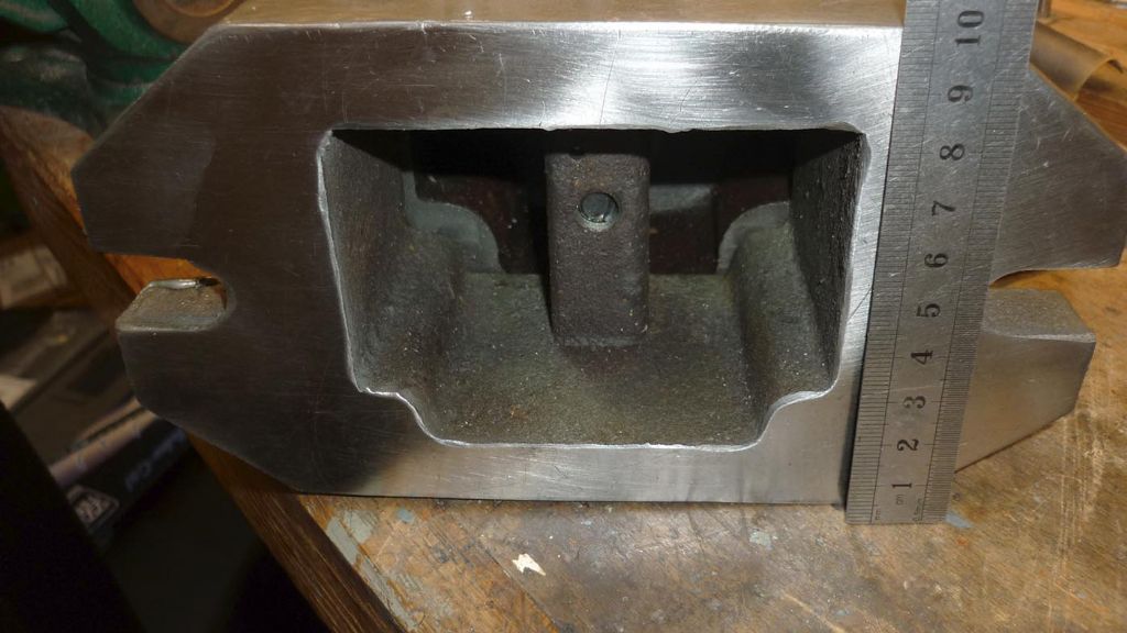
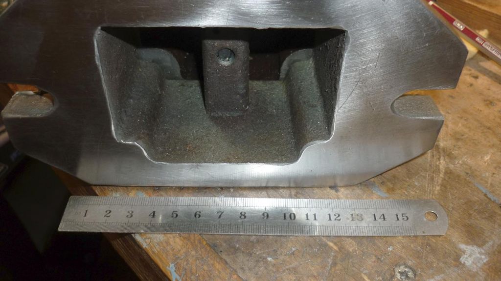
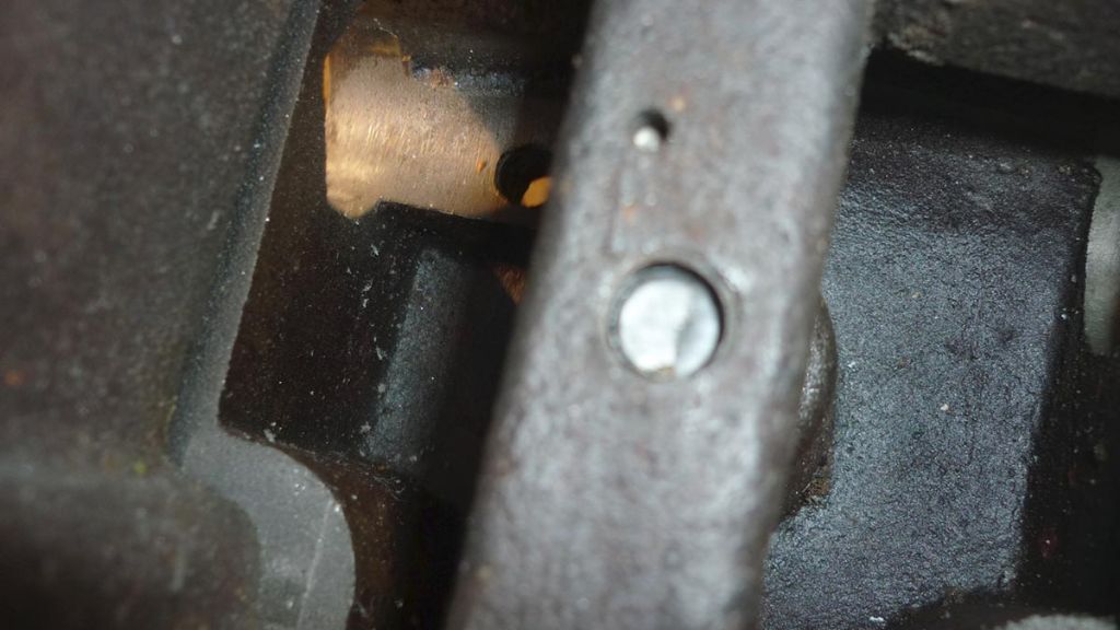
                                                  Heres some more photos of the base ,the thing sits flat on a surface plate,which is something at least .

                                                  The bore through the top is what i think is 2 1/16" and the diameter of the spindle appears to be 1 3/4" ,the straight bushes in each end of the spindle are 7/8" and 3/4" ,so everything is imperial ,probably why google seems to bring up American websites or ebay sales.(i doubt id pay 150$ plus for one of these).

                                                  Cant find any bearings of 2 1/16" outside diameter 1 3/4" internal over here. Maybe just making a couple of bronze plain bushes as bearings would be simplest?? Any thoughts.

                                                  The reason i asked about the bigger diameter change wheel is that i am going to have to bore the centre out to 1 3/4" to go over the spindle i assume.

                                                  From what i have seem from Chinese sites advertising these they are made from Mn65 steel rather than cast iron but im unsure how to distinguish , would that be weldable.(described as a medium carbon toolsteel).

                                                  So the biggest problem i have is securing the two halves of the casting together , if i can get the two parts seperated.blush

                                                  There is a lever on the side the swivels but i dont think is working properly. From what i can tell from the instructions it is only meant to tilt the top half for grinding endmill. Seems a bit strange to me.

                                                  If you look into the base casting there is a larger hole which i assume is threaded for the large bolt that goes right through. Also a small hole next to it with a 1/8" pin which goes right though and rests on the base of the top half. It is free to move in the hole but i can see no way of getting it out with some sort of specially made tool.The only access is a 3/4-1" hole where the other round bar arm goes through the casting.(the bit that holds the adjustable fingers for guiding endmill spirals???

                                                  p1300305.jpg

                                                  p1300307.jpg

                                                  p1300315.jpg

                                                  #267726
                                                  mark smith 20
                                                  Participant
                                                    @marksmith20

                                                    Heres a link to the instructions for this contraption.


                                                    http://www.model-engineer.co.uk/albums/member_album.asp?a=42860


                                                    Edited By mark smith 20 on 21/11/2016 14:38:22

                                                    #267729
                                                    mark smith 20
                                                    Participant
                                                      @marksmith20

                                                      What about turning one of these down on the outside only to fit and cutting in half (half for each side)?

                                                      **LINK**

                                                    Viewing 25 posts - 51 through 75 (of 77 total)
                                                    • Please log in to reply to this topic. Registering is free and easy using the links on the menu at the top of this page.

                                                    Advert

                                                    Latest Replies

                                                    Viewing 25 topics - 1 through 25 (of 25 total)
                                                    Viewing 25 topics - 1 through 25 (of 25 total)

                                                    View full reply list.

                                                    Advert

                                                    Newsletter Sign-up