Digital caliper remote display

Advert

Digital caliper remote display

Home Forums Help and Assistance! (Offered or Wanted) Digital caliper remote display

Viewing 25 posts - 26 through 50 (of 96 total)
  • Author
    Posts
  • #310690
    Neil Wyatt
    Moderator
      @neilwyatt

      I soldered my wires in place. The standard caliper connectors are a joke…

      Neil

      Advert
      #310715
      Bob Mc
      Participant
        @bobmc91481

        Hi Ken, Dave, Neil … and all…

        Just a short digression… as some of you may know I have an interest in astronomy .. my scope is a 6inch binocular reflector… I have a need for a remote digital azimuth angle readout and wondered if anyone has any information for these things…. see pic.. I can't even get into the thing… or if there are any other types which have a remote readout…

        below..pic of scope and below that with angle gauge in question… sorry its blurry but I think you will know the type..

        rgds..Bob..

        dsc_0027a.jpg

        dsc_0081.jpg

        #310725
        Enough!
        Participant
          @enough
          Posted by SillyOldDuffer on 06/08/2017 12:56:52:

          The first problem to overcome is the connector, which I've described as a 'Caliper Plug'. I don't think it's a standard fitting so my first problem will be to make one! It has to fit into the rectangular hole ringed red in the photo, which is normally hidden under a cover.


          Back in the day of the Shumatech DRO's and the use of calipers and other capacitive scales, this connector and its improvised and adapted mates were the source of extensive reliability problems. The general consensus was that directly soldering connecting wires to the pads was a much better way to go – either a short run to a reliable external connector pair or simply the whole run up to the the connector that mates at the readout end.

          Edited By Bandersnatch on 06/08/2017 18:55:11

          #310728
          Les Jones 1
          Participant
            @lesjones1

            Hi Bob,
            I have not taken that type of angle guage apart but I have just had a look at the on I have. If you peel the label off on top of the locking knob there is an alen screw which I suspect will allow yo to dismantle it. Have you considered the "Wixey" type angle gauges ? It is possible to display the data from these remotely and it should be possible to mechanically to the encoder. There is some information on these angle gauges on my website here.

            Les.

            #310741
            Neil Wyatt
            Moderator
              @neilwyatt

              Les got there first

              #310743
              Bob Mc
              Participant
                @bobmc91481

                Thanks Dave for the lcd address program …. will definately have a look at that one.

                Thanks Banders who agrees with Neil that the connector is not a good idea, I soldered mine which is a pita as the case needs taking off otherwise the plastic case will suffer…perhaps Dave will find a better solution.

                Also thanks Les… I didn't know the label hides the screw…and the hack for getting a remote display from the Wixey is what I want….can't understand how I missed that… I think I will be using a rotary encoder for the azimuth display..

                Anyroad up.. I have just been using my new dro and there is a small problem as it seems I selected a couple of resistors for a divider network to give the ~1.5v supply for the calipers, it now transpires that when the battery gets lower in voltage then the caliper voltage goes down as well …obvious! …and the readings dissapear..! so I will be removing the bottom resistor and fitting a zener perhaps or could use an LED as a regulator .. not a big problem.

                Here is a pic of the dro..

                …Bob..

                dsc_0083.jpg

                #310768
                Neil Wyatt
                Moderator
                  @neilwyatt

                  I used LEDs as regulator for mine, but found that using an LM317 or similar gave me fewer glitches.

                  I replaced the batteries in the units with sub-miniature 10uF caps.

                  Edited By Neil Wyatt on 06/08/2017 21:43:35

                  #310776
                  SillyOldDuffer
                  Moderator
                    @sillyoldduffer

                    Wonderful. I log in after a lazy day out to find everyone else has been hard at work!

                    I'd hoped to plug a bigger remote display into an unmodified caliper but the advice about those connectors being unsatisfactory rings true. I could have wasted a lot of time trying to make a satisfactory plug. So I'll solder a caliper up instead. Good job calipers are cheap – being Mr Wobbly with an iron I'll probably melt a few.

                    Les : excellent info on interfacing to a Wixey. I can have a play with one of those now as well. I was going to suggest Bob try an Accelerometer on his binoculars but they aren't as accurate as a level gauge, so double brownie points to you.

                    Cheers,

                    Dave

                    Edited By SillyOldDuffer on 06/08/2017 21:59:15

                    #310779
                    Les Jones 1
                    Participant
                      @lesjones1

                      Hi Bob,
                      I think the rorary encoder is a better solution than either of the angle gauge types. I have a design to display the output of a rotary encoder on an LCD display using a PIC16F690. Let me know if you want the schematic and code for the PIC. I have seen some 600 counts per rev encoders on ebay for less than £10.00 so one of them geared 6:1 to the telescope axis would give 0.1 degree resolution.

                      Les.

                      #310960
                      Zebethyal
                      Participant
                        @zebethyal

                        I took the Yuriy's Toys approach for the DRO on my Mini Mill that uses Igaging scales but built my own circuit board based on an atTiny85 and some USB connectors (total cost less than £5.00). This runs Yuriy's firmware with a couple of minor tweaks for the atTiny chip.

                        This interfaces via Bluetooth to a cheap 10" Android tablet, but any Andriod device would work just as well.

                        The Igaging scales use mini USB cables, but use +3v, Clk, Data, Gnd on the pins

                        Edited By Zebethyal on 08/08/2017 11:05:24

                        #310973
                        Neil Wyatt
                        Moderator
                          @neilwyatt

                          Many moons ago I bought a carbon fibre caliper off eBay because it was silly cheap as a 'hack'. Didn't notice it was only 0.01"/0.1mm. this thread reminded me of it, so I've fitted it to my pillar drill as a depth gauge after cutting most of it to pieces. No sense trying for 1-thou accuracy on a drill, if I need that I can us the mill.

                          Goes nicely with a laser centring device from Machine DRO so I'll put some pics in the next MEW.

                          Neil

                          #310997
                          SillyOldDuffer
                          Moderator
                            @sillyoldduffer

                            Lack of progress report!

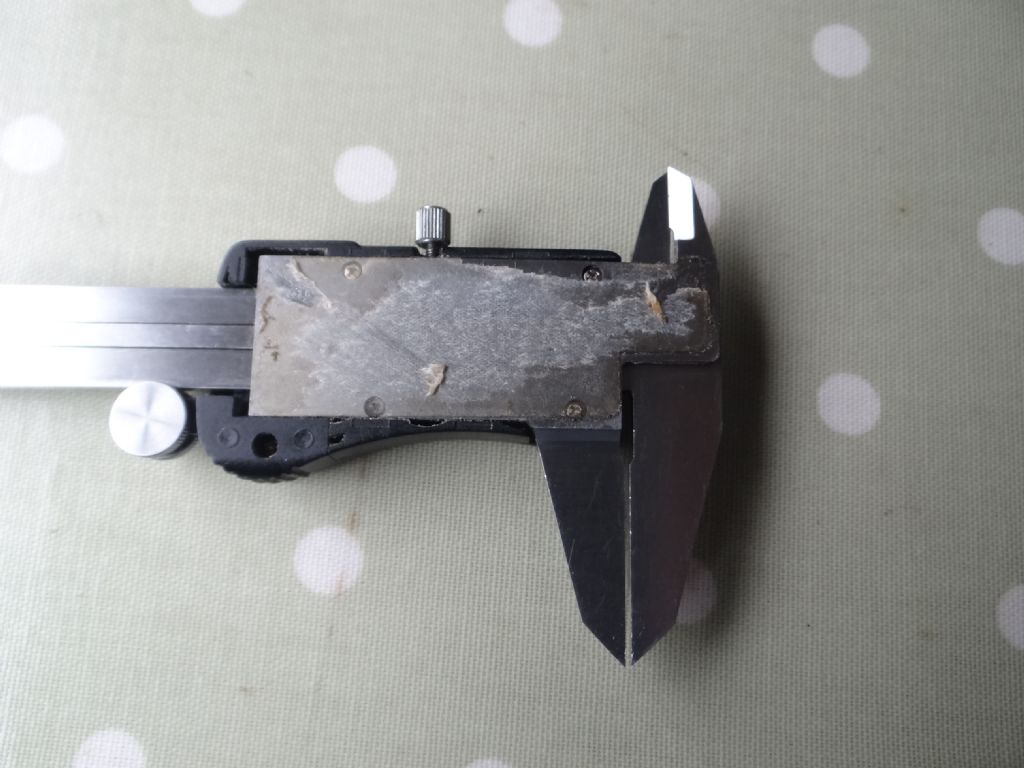
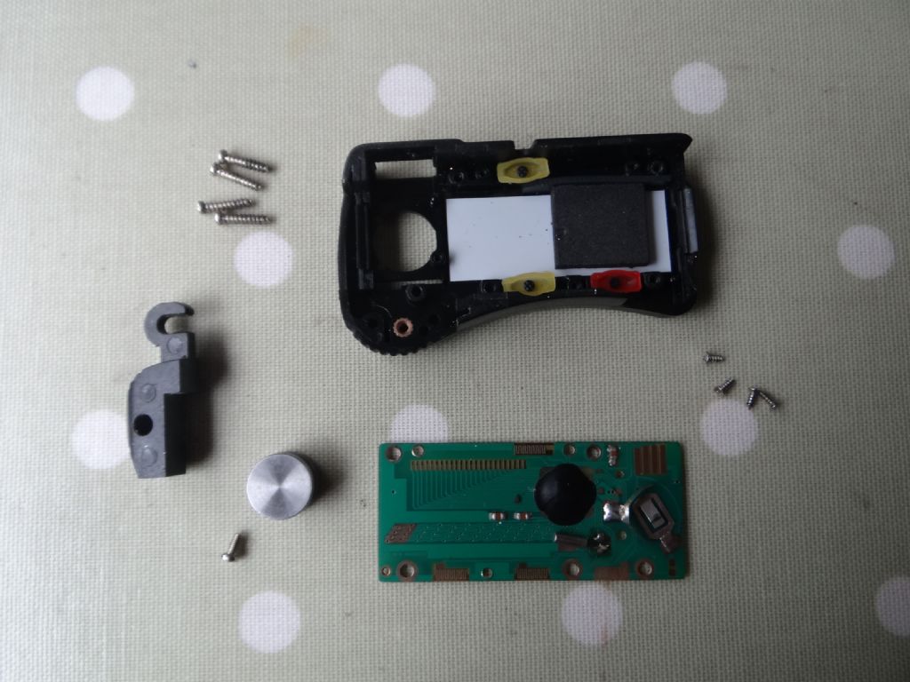
                            Good news, my old Powerfix Caliper came apart easily after exposing the screws behind the sticky label on the back.

                            dsc04510.jpg

                            dsc04511.jpg

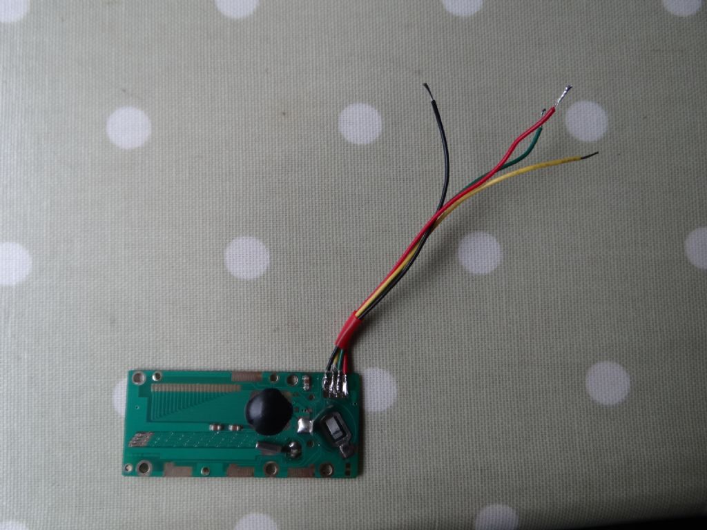
                            Even better, a signal appeared on the 4 pin interface after I cleaned out the swarf so I shakily soldered on some wires. (I was surprised how much muck was inside the case.)

                            dsc04512.jpg

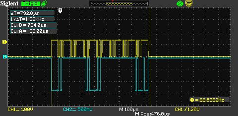
                            Reassembled I detected this output on the clock and data pins. The yellow trace is the clock, and the blue is the data. As expected I found the caliper never switches off. The ON/OFF button disables the display but everything else carries on working.

                            caliper_protocol.jpg

                            After this promising start the project's gone pear-shaped. The NPN transistor level shifter quickly drains the caliper's battery. I've been unable to decode the data with any of the Arduino sketches available on the web. I can't see any difference between positive and negative numbers on the oscilloscope trace. This might indicate this caliper has an unusual variation on the usual protocol. Or that I'm a bit thick.

                            Perhaps a mug of strong coffee and an hour on the lathe will sort me out. Electronics and computers have lost their appeal.

                            Dave

                            #311028
                            Les Jones 1
                            Participant
                              @lesjones1

                              Hi Dave,
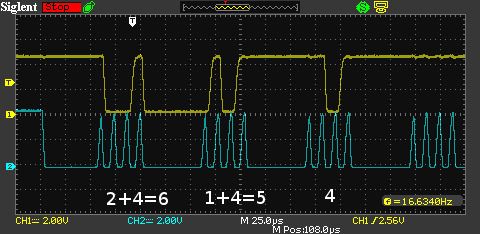
                              The waveform looks like 7 BCD protocol but the data is inverted. I can't remember if any versions of Yuriy's code support this protocol. This is a link to a website that shows the 7 BCD code. I have a powerfix caliper (From Lidle) but the one I have looks like 2 x 24 bit protocol.

                              This is some notes I made on the 7 BCD protocol on a set of calipers bought from Neto many years ago.

                              ————————————————————————-
                              7 BCD Scales
                              LSB Sent first.

                              Static state of clock line between frames Low
                              Time between start of frames 330 mS
                              Length of data frame 820 uS
                              Interrecord gap 329 mS
                              Time between stat of nibbles within frame 110 uS
                              Length of clock cycle about 12 uS
                              Time clock pulse is negative about 6 uS
                              Time clock pulse is positive about 6 uS
                              High level at start of frame about 55 uS
                              High level between nibbles about 60 uS
                              High level at end of frame about 60 uS

                              Clock in the data on the negative going edge.

                              Top nibble
                              Bit 0: sign. L = +, H = –
                              Bit 1: in inch-mode H means +0,0005 inch, unused in mm-mode.
                              Bit 2: unit: mm/inch. H= mm; L= inch
                              Bit 3: unknown.

                              28 bits in a frame of data

                              CPI 2540 (Metric)
                              ————————————————————————-

                              My interface design using an ATtiny4313 worked with this 7 BCD caliper. Let me know if you would like a copy of the source code (Written in assembler.) It may give you some ideas to write a version in "C" to run on the arduino.

                              Les.

                              #311040
                              Bob Mc
                              Participant
                                @bobmc91481

                                Hi Dave…

                                I can certainly commiserate with you "electronics & computers losing their appeal" .

                                Les is right…the trace definitely looks like a BCD format see .. http://robotroom.com/Caliper-Digital-Data-Port-3.html

                                which means you will be able to use my code..as posted.

                                I also didn't use the battery in the calipers rather using the +5v from the Arduino for the level shifter… and potting down the 3v3 from the Arduino for the caliper 1.5v supply using two 6k2 resistors.

                                The LCD I originally powered using the +5v Arduino supply but I found it caused the screen to be a bit dim….the maximum LCD volts is 7v, so rather that making a power supply circuit for this, I found a 3.3v zener and put it in series with the LCD and the 9v Battery… now its as bright as needed.

                                rgds..Bob..

                                #311080
                                SillyOldDuffer
                                Moderator
                                  @sillyoldduffer

                                  Hi Bob and Les,

                                  I can confirm that this caliper is using BCD. This screenshot is of 4.56mm and you can see the first three nibbles are 6, 5 and 4. Hurrah!

                                  d456.jpg

                                  At the moment I'm using a slightly modified version of Bob's sketch. The main differences are: I've commented out the I2C LCD stuff and am using the Serial Monitor instead; I've also inverted the start logic in ReadX()

                                  The start logic change is because my caliper appears to be upside down. After making the change I started receiving numbers and was able to confirm that the delay between each transmission is correctly detected by the Arduino.

                                  Trouble is that the decoded numbers jump about and don't have any relationship to the input. I'd be much happier if the output numbers were stable even if wrong. As it is, looks like the Arduino and/or Sketch aren't detecting bits properly.

                                  It may be noise on the caliper's "power supply". I'm running a LED off the 3.3V line and tapping 1.5V off that smoothed with 6.8uF. I don't think the erratic numbers are due to logic inversion or Bob's code, but might be. My main suspect at the moment is the level shifter: the clock signals in particular are suspiciously round-shouldered!

                                  Many thanks for the advice. I have a way to go yet!

                                  Dave

                                  #311082
                                  Neil Wyatt
                                  Moderator
                                    @neilwyatt

                                    My digital scales don't send the data in the BCD form, instead they use this:

                                    "The 48-bit serial stream contains two 24-bit words that are the absolute and relative positions of the scale in binary format, not BCD format like the Digimatic protocol. Each 24-bit word is sent least significant bit (LSB) first, which is opposite from most serial protocols that send the most significant bit (MSB) first. The units of each word are in 20,480 positions per inch or 0x5000 in hexadecimal. The first word is the absolute position of the scale with an arbitrary origin that remains fixed until the scale loses power. The second word is the relative position of the scale with an origin that is reset with every press of the zero button on the scale. The positions are signed values so negative values are expressed in two's complement notation. A diagram of the data format is given below."

                                    You can see this potentially allows you to read the scale to a tenth of a thou or even a micro-metre. This is so the same protocol can be use with micrometers and other higher precision devices. In practice I found that 0.0005" or 0.01mm were practical. I used 3x oversampling which helped minimise display flicker.

                                    Neil

                                    #311090
                                    duncan webster 1
                                    Participant
                                      @duncanwebster1

                                      This is getting stupendously interesting, I'm learning lots of new stuff. Whether it will stay in the ageing grey matter is debatable!

                                      BobMc code of 05/08 seems to have lots of spare curly braces in the setup() routine, and SoD code of 06/08 has several #include lines which don't seem to include anything. Can these erudite gents put me wise?

                                      #311111
                                      Bob Mc
                                      Participant
                                        @bobmc91481

                                        Hi Duncan../..Dave..

                                        Duncan..Yes you are right…! there are a lot of curly braces in the setup and to be honest I don't know why! but this prog was copied off the www. and since it worked I didn't see any reason to alter it apart from making it read two calipers.. I must admit again that I am certainly not an expert with programming these things, Dave seems to have a far better understanding of programming.

                                        Dave…. you say you have fitted a capacitor to get rid of sporadic readings… I fitted mine at the caliper end which stopped a similar problem… which Neil has done as well.

                                        ..Bob..

                                        #311125
                                        John Haine
                                        Participant
                                          @johnhaine32865

                                          This all looks very interesting and I can feel a project coming on to fit scales to my VMB, especially as I'm just getting into Arduino. Bob, are you thinking about adding a 3rd axis by any chance please?

                                          And Neil, any chance of being able to post other file types here? Or should we just use Github?

                                          #311126
                                          SillyOldDuffer
                                          Moderator
                                            @sillyoldduffer
                                            Posted by duncan webster on 08/08/2017 22:19:44:

                                            BobMc code of 05/08 seems to have lots of spare curly braces in the setup() routine, and SoD code of 06/08 has several #include lines which don't seem to include anything. Can these erudite gents put me wise?

                                            Hi Duncan,

                                            Bob's extra curly brackets can be removed if you like. (I haven't bothered.) They're usually a sign of a program that's been developed but not tidied up once it works. The brackets probably contained unwanted code like debugging statements now removed.

                                            Posting source code on the forum is fraught with danger because the forum editor has a mind of its own! It destroys indentation by removing 'superfluous' white space, converts certain character combinations into smileys, and – new one on me – removes anything between '<' and '>' brackets.

                                            The missing #includes in my post of Nick Gammon's scan sketch are Wire.h and LiquidCrystal_I2C.h (The third missing #include in the scanner code is an unnecessary repeat of Wire.h that can be deleted.)

                                            Dave

                                            #311128
                                            Ken Weeks
                                            Participant
                                              @kenweeks58536

                                              Well we have certainly covered a lot of ground since my first question.

                                              I have said before that I am always amazed by the amount of information, comments, help and advice freely given on these forms.

                                              Bob/Silly Old Duffer Any chance of giving links to the sites where you found the code?

                                              My Tail Stock and Vertical Slide are both fitted with calipers.

                                              I am trying to get my head around making a read out that would allow them to be plugged as required.

                                              Ken

                                              #311129
                                              SillyOldDuffer
                                              Moderator
                                                @sillyoldduffer

                                                After a few tweaks last night chaos ensued; the caliper displayed weird values and refused to zero; the oscilloscope triggered erratically and the caliper clock waveform looked like it was charging a capacitor. Suspecting a short in my birds nest lash-up I pulled everything apart this morning. After reducing the project to a pile of bits I noticed that the power plug had fallen out of my USB hub…

                                                I'm out today and won't make much progress.

                                                Dave

                                                #311140
                                                Bob Mc
                                                Participant
                                                  @bobmc91481

                                                  Hi all …John/Ken

                                                  John Haine asks about a 3rd axis display…

                                                  the program I posted could be altered for this purpose, but I can only give an indication of what would need to be done, which is to copy one of the sub programs for example 'void Read Y' and change all the Y's & y's to Z & z's

                                                  then insert an instruction to 'Read Z' after 'Read Y' was finished…and back to 'Read X' after 'Read Z' is finished, you would also have to alter the Setup & definition parts to include the inputs/outputs etc… I am not able to provide much more info as I am busy making a readout for my mill using a rotary encoder.. you would also need to find a bigger display than I used in my build.. mine could show 3 readings but only on two rows…

                                                  Hi Ken… "come a long way" …..yes I only wanted to show it could be done..! to be honest I can't remember exactly where I got the program from perhaps it would be better to wait and see what Dave comes up with as the program I posted has got a lot of superfluous material and wants thinning down, there are certainly a number of people on the www giving programs for this and it does seem the case that most of the cheap calipers are using the BCD format…Binary Coded Decimal.

                                                  One of the things that could be done in the meantime is to get an LCD display, mine is a 16×2 character lcd and find out how to write to it… that would be a good start and it is quite simple, if you can get that up and running using an arduino you are half way there… lcd's are about £5 quid on ebay.

                                                  Bob…

                                                  #311175
                                                  Ken Weeks
                                                  Participant
                                                    @kenweeks58536

                                                    I found these two sites helpful

                                                    This one has a layout including the LCD and code for a 3 axis dro using calipers.

                                                    https://www.thingiverse.com/thing:1731982

                                                    This one shows using a

                                                    SparkFun Logic Level Converter – Bi-Directional

                                                    as the interface between the arduino and the caliper.

                                                    wei48221.blogspot.co.uk/2016/01/using-digital-caliper-for-digital-read_21.html

                                                    I contacted the first site and he says the logic level converter could be used in place of his board circuits

                                                    Ken

                                                    #311215
                                                    Enough!
                                                    Participant
                                                      @enough

                                                      A lot of this, particularly noise issues with the capacitive scales and different coding systems, was covered extensively some years ago in the Shumatech Yahoo group, and is reinventing the wheel a bit here. It may be more trouble than it's worth to search there though (particularly if you are not a member) – it is Yahoo after all.

                                                      A better alternative might be to have a look at Rick Barber's Page covering the Shumatech DROs.

                                                    Viewing 25 posts - 26 through 50 (of 96 total)
                                                    • Please log in to reply to this topic. Registering is free and easy using the links on the menu at the top of this page.

                                                    Advert

                                                    Latest Replies

                                                    Viewing 25 topics - 1 through 25 (of 25 total)
                                                    Viewing 25 topics - 1 through 25 (of 25 total)

                                                    View full reply list.

                                                    Advert

                                                    Newsletter Sign-up