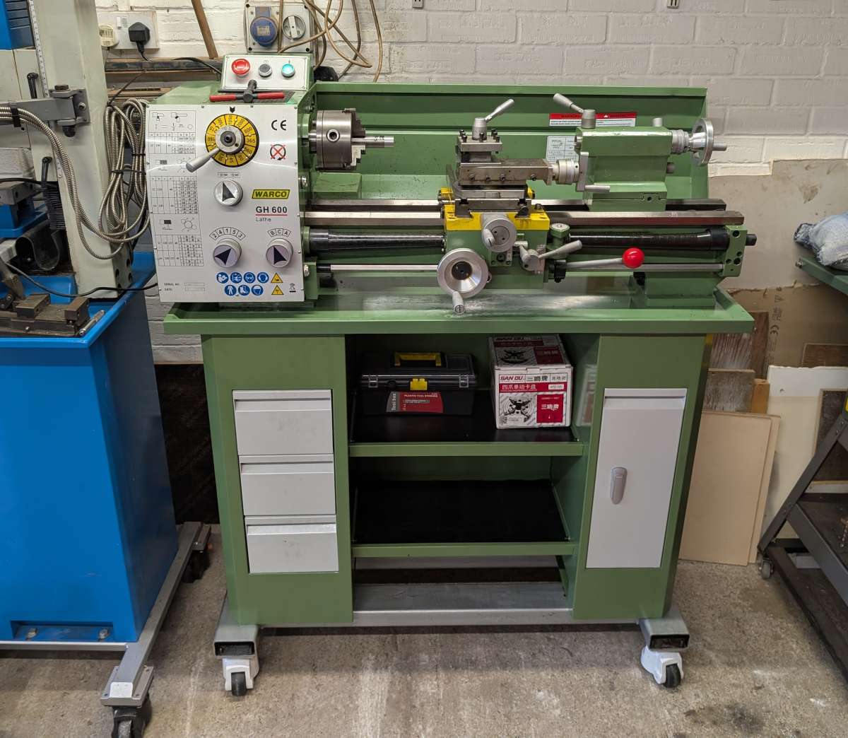
Design Advice!- Warco GH600 Solid Topslide
Design Advice!- Warco GH600 Solid Topslide
- This topic has 24 replies, 9 voices, and was last updated 30 May 2025 at 08:58 by
 Richard Kirkman 1.
- Please log in to reply to this topic. Registering is free and easy using the links on the menu at the top of this page.
Latest Replies
-
- Topic
- Voices
- Last Post
-
-
Warco Super Major Milling Machine – Stripping Gearbox
Started by:
Lee Jones 6
in: Manual machine tools
- 10
-
29 August 2025 at 17:47
Colin Heseltine
-
End Mill Sharpening Jig
Started by:
Vic
in: Workshop Tools and Tooling
- 7
-
29 August 2025 at 17:26
Martin Kyte
-
interchangeable Myford beds
Started by:
Kundrus
in: Manual machine tools
- 4
-
29 August 2025 at 15:43
Kundrus
-
Hello.
Started by:
smokeyjoe25
in: Introduce Yourself – New members start here!
- 3
-
29 August 2025 at 14:38
bernard towers
-
Modular 3/4 inch TE info required
Started by:
Loose nut
in: Traction engines
- 5
-
29 August 2025 at 14:14
teamricky
-
Weird electric actuator action
Started by:
ell81
in: Beginners questions
- 5
-
29 August 2025 at 13:14
ell81
-
Mercer comparator gauge repair help.
Started by:
Graeme Seed
in: Workshop Tools and Tooling
- 4
-
29 August 2025 at 12:47
Graeme Seed
-
Painting mating surfaces
Started by:
Martin Cooper
in: Beginners questions
- 10
-
29 August 2025 at 12:35
SillyOldDuffer
-
125 mm chuck onto my lathe
Started by:
Steve Huckins
in: General Questions
- 12
-
29 August 2025 at 11:56
SillyOldDuffer
-
Indicator bulb with bayonet mount needed
Started by:
Wade Beatty
in: Electronics in the Workshop
- 6
-
29 August 2025 at 09:20
Wade Beatty
-
Smart & Brown Model L lathe help required
Started by:
AJAX
in: Manual machine tools
- 4
-
28 August 2025 at 20:50
AJAX
-
Progress no.1 restoration
Started by:
flyingsailor
in: Workshop Tools and Tooling
- 9
-
28 August 2025 at 20:31
old mart
-
boiler leak
Started by:
Bill Dawes
in: Locomotives
- 12
-
28 August 2025 at 19:07
Bill Dawes
-
Bendy Flexible Plywood
Started by:
Henry Buckeldee
in: Related Hobbies including Vehicle Restoration
- 14
-
28 August 2025 at 18:13
Henry Buckeldee
-
Lathe tool inserts
Started by:
Andy Brocklehurst
in: Beginners questions
- 9
-
28 August 2025 at 18:08
Diogenes
-
Museum donation
Started by:
Stephen Wessel 1
in: Introduce Yourself – New members start here!
- 4
-
28 August 2025 at 16:18
Stephen Wessel 1
-
Damp engine, Name?
Started by:
sivtek1
in: Stationary engines
- 6
-
28 August 2025 at 13:58
cogdobbler
-
Phone Phreaking
Started by:
Michael Gilligan
in: Clocks and Scientific Instruments
- 13
-
28 August 2025 at 08:13
Roger Hart
-
What Did You Do Today 2025
1
2
…
9
10
Started by:
JasonB
in: The Tea Room
- 36
-
28 August 2025 at 00:07
howardb
-
Granville lathe leadscrew change wheel
1
2
Started by:
JACK SIDEBOTHAM
in: Help and Assistance! (Offered or Wanted)
- 13
-
27 August 2025 at 21:06
Howard Lewis
-
Marcus Oxen … illustrated notebook
Started by:
Michael Gilligan
in: The Tea Room
- 2
-
27 August 2025 at 16:45
Harry Wilkes
-
Softening epoxy
1
2
Started by:
John Haine
in: General Questions
- 21
-
27 August 2025 at 12:56
Robert Atkinson 2
-
Hereward
Started by:
Richard Simpson
in: Model Boats
- 6
-
27 August 2025 at 11:06
cogdobbler
-
Imperial Bearing Surprise!
Started by:
Peter_H
in: General Questions
- 4
-
27 August 2025 at 10:06
tonychap
-
QCTP for chester lathe
1
2
Started by:
Chris12
in: Beginners questions
- 12
-
27 August 2025 at 08:17
Vic
-
Warco Super Major Milling Machine – Stripping Gearbox
Latest Issue

Newsletter Sign-up
Latest Replies
- Warco Super Major Milling Machine – Stripping Gearbox
- End Mill Sharpening Jig
- interchangeable Myford beds
- Hello.
- Modular 3/4 inch TE info required
- Weird electric actuator action
- Mercer comparator gauge repair help.
- Painting mating surfaces
- 125 mm chuck onto my lathe
- Indicator bulb with bayonet mount needed

