Cross slide dial calibrations – opinions sought.

Advert

Cross slide dial calibrations – opinions sought.

Home Forums Manual machine tools Cross slide dial calibrations – opinions sought.

  • This topic has 33 replies, 22 voices, and was last updated 18 May 2020 at 10:17 by Nigel McBurney 1.
Viewing 9 posts - 26 through 34 (of 34 total)
  • Author
    Posts
  • #472015
    Andy Stopford
    Participant
      @andystopford50521

      Thanks everyone for your thoughts. I'm going to go for diameter – to me it is more logical, and if I hate it, well, I'll just have to make another dial.

      With regard to DRO, it's a very small lathe, and I think attaching things to the saddle/cross slide is potentially adding clutter to get in the way – length-ways along the bed and on the tailstock like Stuart's setup is a very attractive idea, however. I'll keep an eye out for cheap calipers in Lidi and Adl.

      Advert
      #472051
      oldvelo
      Participant
        @oldvelo

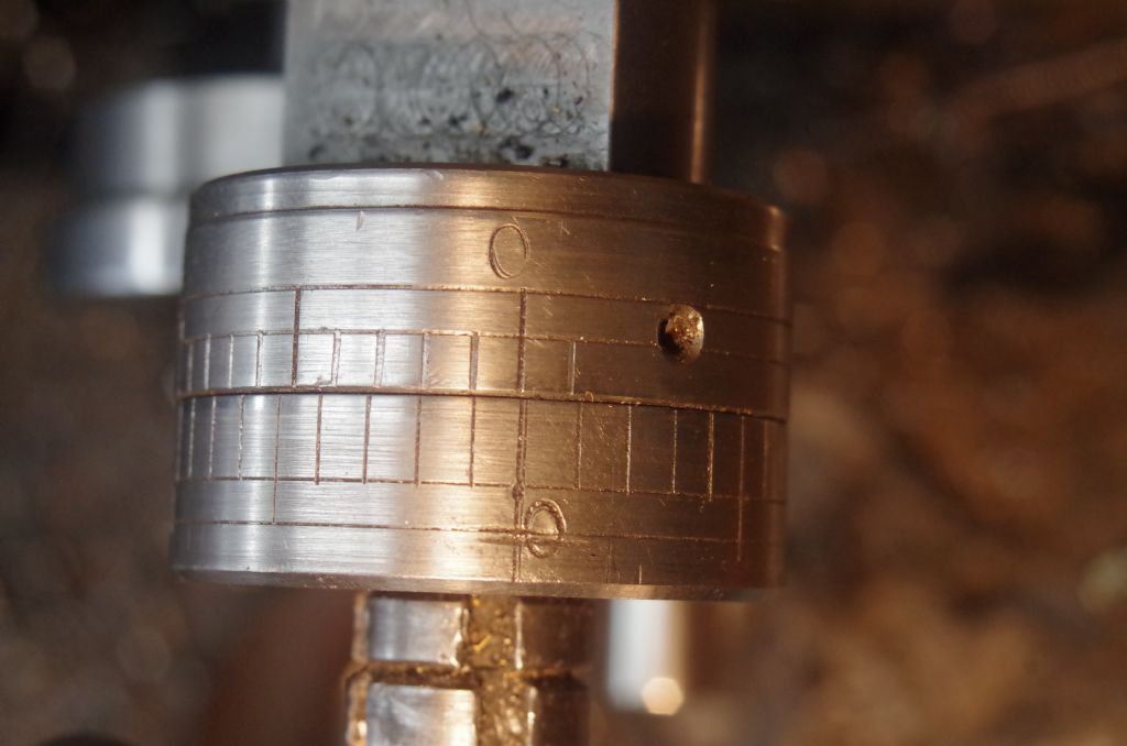
        Possibly of use to someone reading this thread 2 mm pitch crossfeed screw with vernier scale on the static dial

        to read in 0.01 mm increments with the Static Dial on the top.

        Rotary dial has 40 divisions. Static dial has 44 divisions. Readings are on the work diameter trom right to left.imgp3352.jpg

        Eric

        Edited By oldvelo on 16/05/2020 05:18:29

        #472292
        Stuart Smith 5
        Participant
          @stuartsmith5

          Andy

          My lathe is a cj18a mini lathe from amadeal – I think the same as yours.

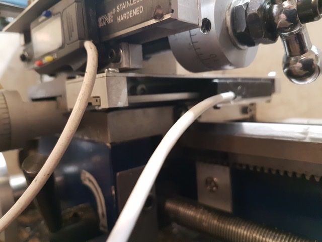
          Here is another photo of the way I mounted the caliper for the crosslide. It stops access to the carriage lock, but other than that I haven’t found it a problem. The caliper for the top slide is ok apart from when you want to set it at an angle – I have to unscrew it then.

          Crosslide caliper

          I found a couple of issues with the cheap calipers which I managed to fix in the software/ interface. Because I am powering the calipers from the interface PSU, when I switch it on it always starts in inches mode and after a while, the output from the calipers stops (they go to sleep). I have used extra outputs from the Arduino to automatically change to mm mode and to detect if the output stops and switch it back on.

          The touch DRO app has the facility to add 2 readings so I have mine add the top slide and carriage caliper outputs and display as one.

          If you decide to have a go with these calipers, let me know and I can send you the code and interface details.

          Stuart

          Edited By Stuart Smith 5 on 16/05/2020 21:34:49

          #472448
          Peter G. Shaw
          Participant
            @peterg-shaw75338

            I have a Warco 220 lathe which is a rebadged Mashstroy 210T. The cross-slide dial is dual calibrated but I only use metric divisions. The dial shows amount taken off the diameter which I do not have any problem with at all. If anything, it is convenient because I usually measure the diameter of the workpiece, determine how much to take off, and then set up the cross-slide to reduce the diameter by that amount. The vast majority of what I do concerns work in the round, indeed I cannot recall any occasion where the linear movement (2mm pitch by the way) has been necessary. In any case, I can't see it being a problem halving the dial readings.

            Where the dials do fall down is that the graduations are 0.05mm apart which means that for diameter reductions of less than 0.05mm, I have to estimate how far to turn the dial past the appropriate marking, however, I do find it relatively easy to estimate down to 0.01mm by using the guidelines suggested in a document produced by the National Physical Laboratory – Good Practice Guide No.40 in which they suggest that the thickness of the calibration lines on the dials should be equivalent to 20% of the distance between calibration lines. Therefore, for me to remove 0.01mm from, say, a diameter of 10.01mm, requires me to set the dial markings such that one side of the appropriate movable dial marking coincides with the opposite side of the fixed or fidudicial line.

            Estimating to 0.025mm is easy – halfway between any two marks. Similarly, 0.0333mm or 0.0666mm is easy – simply set the movable dial such that the fixed marking is at 1/3 or 2/3 as appropriate.

            The same article also discusses the effects of heat, or the lack of it, and certainly in my case, with temperatures in my shop which can vary between cold and warm (extreme variations of these and I abandon work) there would seem to be very little point in me attempting to work to 0.001mm.

            The document mentioned above was recommended by someone, possibly Neil Wyatt, as being available for download, which is what I did, hence I cannot tell you how to obtain it. What I can say, is that it is a very interesting read covering, as it does, micrometers and caliper, including care & maintenenance along with how to use them.

            Peter G. Shaw

            #472461
            Neil Wyatt
            Moderator
              @neilwyatt

              0.025 isn't hard to work with if you think of it as 0.05 off the diameter.

              Neil

              P.S. I don't think it was me, Peter?

              Edited By Neil Wyatt on 17/05/2020 16:44:03

              #472475
              Peter G. Shaw
              Participant
                @peterg-shaw75338

                In that case Neil, I don't know from where I got the info. All I know is that someone in the ME world mentioned it, I downloaded it, and stored it on my computer.

                Having searched for it, it can be found via the NPL website, but they do want some details from you.

                Peter G. Shaw

                #472526
                Andy Stopford
                Participant
                  @andystopford50521

                  Hi Stuart, yes, I'd definitely be interested to see your code etc., I'm not sure what the arrangements are for sending messages here, maybe one of the mods can advise.

                  I'd actually be looking first to fit DROs to my mill – I've fitted carriage stops to it, which are useful, but it would be nice to have read-outs.

                  #472550
                  Stuart Smith 5
                  Participant
                    @stuartsmith5

                    Andy

                    I have sent you a PM. See your inbox at the top of the screen when logged in.

                    Stuart

                    #472627
                    Nigel McBurney 1
                    Participant
                      @nigelmcburney1

                      All very interesting,My imperial Myford reads on radius and my Imperial Colchester fitted with dual dials reads off diameter,have got used to it,though my basic training years were on traditional english lathes . Mention is made of Henry Maudlay ,did his machines with dials indicating radius,stem from his work on screwcutting, where all threads were dimensioned by diameter ,thread pitch and thread depth, It is easier when screwcutting to have an index dial which indicates depth of cut ,rather than indicating diameter. Plus early lathes were put to many uses,eg boring and machining with work held on the crosslide,and carried on with Myford and Boxford(and others) where the dial indicating actual cross slide travel is far more useful. Apparently Maudslays lathe had an indexing dia,,but a lot of Victorian era machines only had crank type handles on the screws with no index dials,back in the 60s my neighbour still owned the engineering worskhop his father had set up to support his agricultural and thrashing buisiness in the 1880s,the buisiness closed before ww11 but mneighbour loved his steamers and retained them and the workshop until the end of the 60s. he had three lathes,two six inch and a rather large 12 inch lathe,plus small planer none of these machines had an index dial, I remember telling my boss about them,his comments were that most machines of that era had no dials,the turners worked with stiff joint calipers and steel rules and chalk marks on the handles,they never used spring type calipers,and only the foreman had micrometer.and apparently they produced good work though no doubt this is where the term for their trade was "fitter and turner".When I only had a Myford,with a vertical slide and index handwheel on the leadscrew,it would have a real pain if the crosslide did not have radius reading dials when milling .

                    Viewing 9 posts - 26 through 34 (of 34 total)
                    • Please log in to reply to this topic. Registering is free and easy using the links on the menu at the top of this page.

                    Advert

                    Latest Replies

                    Home Forums Manual machine tools Topics

                    Viewing 25 topics - 1 through 25 (of 25 total)
                    Viewing 25 topics - 1 through 25 (of 25 total)

                    View full reply list.

                    Advert

                    Newsletter Sign-up