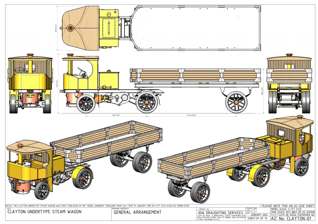
Clayton Steam Wagon

Advert

Clayton Steam Wagon

Home Forums Traction engines Clayton Steam Wagon

Viewing 22 posts - 1 through 22 (of 22 total)
  • Author
    Posts
  • #604186
    Paul Lousick
    Participant
      @paullousick59116

      For anyone interested in building a Clayton Undertype Steam Wagon, detail drawings in PDF format and Solidworks are free to download on the GrabCad website.

      **LINK**

      clayton steam.jpg

      clayton-undertype-wagon.jpg

      Advert
      #3004
      Paul Lousick
      Participant
        @paullousick59116
        #604196
        JasonB
        Moderator
          @jasonb

          Just be careful with Julius' drawings some details including the boilers can have issues

          #604203
          Paul Lousick
          Participant
            @paullousick59116

            Thanks Jason,

            If I did build one, the boiler would probably, have to be modified to comply with our code in Australia. And like many drawings for model engines, should be checked for mistakes. Most contain errors.

            Edited By Paul Lousick on 04/07/2022 10:31:00

            #801034
            Werner Schleidt
            Participant
              @wernerschleidt45161

              I have a question for my friend, he had built a 2 inch Clayton wagon. The Clayton is running with a pressure of 3 bar or 42 psi good, but if he have 6 bar / 84 psi his expectation is that the clayton runs faster and more powerful.

              This is not visible. At the moment we have no idea how this behaviour is possible.

              Many thanks if there are any ideas or better some experience how this can be.

              Many thanks inadvance

              Werner

              Ps the design is converted to metric from a Julius drawing

              #801065
              Nigel Graham 2
              Participant
                @nigelgraham2

                Doubling the boiler pressure will certainly give more power but if the boiler was designed for 3 Bar it will need re-designing for that increased pressure.

                It will significantly increase, but not necessarily double, the engine power.


                The power generated in a steam-engine is directly related to the “Mean Effective Pressure” (MEP) in the cylinder, not the boiler pressure. This is a sort of “average” set by the valve-gear settings and much more arcane factors like exhaust compression, clearance volume and heat loss.

                The maximum pressure acting on the piston, before cut-off, will never be as high as the boiler pressure even at fullly-open regulator, due to various throttling effects on the steam’s journey from the boiler.

                The efficiency also depends on whether the steam is superheated or not. I do not know if this Clayton is superheated, but superheating increases the amount of heat available for conversion to mechanical energy, and keeps the steam above its condensation point for longer during the piston stroke.


                If you want to calculate the power:

                The basic formula for one end of one cylinder using Imperial units is PLAN / 33000,

                where P is the MEP – a function of full pressure in the cylinder before cut-off, and the roughly hyperbolic expansion after cut-off.

                L = Length of piston stroke in feet.

                A = Piston area in Square Inches.

                N = number of working strokes per minute (or rpm), but for a double-acting cylinder multiply that by 2.

                33000  is the foot-pounds to horsepower converter.


                Sorry- I don’t know how it all works in SI units. I can convert the dimensions from inches to mm easily enough but I don’t know how to make the mm sizes and bar (or Pa) give the right number of Watts. Named after the chap who invented the Horse-power….

                I would need calculate the engine from its inch-units dimensions to give HP, then multiply that by 746 to give Watts.

                .

                Then to add to the fun, in practice the actual power is never as much as that, so multiply it by an efficiency-estimate called the “Diagram Factor”, very difficult to determine without an engine-testing laboratory. Even in the days when the Clayton company was trading, it seemes to have been a rule-of-thumb value. For a model engine I’d think 0.8 fair, though it may be less than that.


                So building your Clayton to run at the higher pressure will certainly make it more powerful but you do need consider the practicalities – especially and vitally the boiler.


                The overall results of the model Locomotive Efficiency Competitions reveal just how inefficient even the best of these small machines really are. I think this is largely because the internal losses have a proportionately larger effect the smaller the engine; but even the full-size ones are not particularly efficient.

                ……

                “Diagram Factor” from the use of the Indicator Diagram to test full-size engines. This instrument draws a graph of pressure against stroke, on a pro-forma card, and the power can be determined from integrating the resulting closed shape. The integrator instrument was usually a planimeter.  The plot is also diagnostic, showing the effects of the valve functions, and inequality of power generated in each end of the cylinder due to the volume occupied by the piston-rod.  The factor is the comparison of calculated and measured powers.


                #801079
                JasonB
                Moderator
                  @jasonb

                  Speed alone  is controlled by the amount of steam getting to the cylinder not the pressure of the steam.

                  You do not alter the pressure when going from tick over to full speed, you use the regulator to adjust the volume of steam that can get to the cylinders.

                  I can run an engine at 100rpm right through to  2500rpm without changing pressure from 0.3bar, I just regulate the flow.

                  I would be looking a how far the regulator can open, valve travel to see if they are fully opening the ports, size of drilled passages, etc  but as Julius designs can have errors it could be something else.

                  Pressure will effect power so depending on load will increase performance.

                  #801101
                  Werner Schleidt
                  Participant
                    @wernerschleidt45161

                    Many thanks Nigel and Jason,

                    Nigel,

                    there is a misunderstanding, the boiler is made for 6 bar working pressure, but the clayton is able to run if the pressure is only 3 bar in the boiler. perhaps I do not discribed it good to understand, but with 3 bar boiler pressure or 6 bar boiler pressure and throthle valve full open, there is not so much difference to see in the driving behaviour. Thanks for the formulas, for me it is no problem to calculate in inches it needs only more work, because I am not so familar with it, I grow up metric. So I have to make more calculations to have a feeling what I can get.

                    Jason,

                    thank you for your suggestions. As you mentioned there could be some error in the drawing. It seems to be that there is some throttling effect in the cylinder. Personally for me it is strange for me that between the D valve top and the cylinder cover is only a small gap of 2 mm and so my feeling is that the pressure in the valve housing is not equal at all ports and there is some throtteling at higher flow and pressure. Under compressed air the engine is running free and the rpm depending to the pressure. We have the feeling that at higher steam pressure there is more chance that water came with the steam to the cylinder. The boiler has no overheater, because he made worst experience with a copper pipe which is worn out and he had copper in the valve box.

                    Werner

                    #801111
                    noel shelley
                    Participant
                      @noelshelley55608

                      There are numerous works on the issue that Werner mentions. Whilst Wardale goes down the road of exhaust efficiency, L.D.Porta did what could best be described as “gas flowing” a loco. To my mind it doesn’t matter how good the boiler is if the power generated can’t get to the cylinder – and out it’s all a waste of time. A poorly designed regulator, rough cast steam ways, sharp bends and small port ways will all conspire to reduce the power available at the piston rod. Noel.

                      #801113
                      JasonB
                      Moderator
                        @jasonb

                        Unfortunately I don’t have the original Clayton drawings to compare things with. Also not sure if they used drilled or cored passages. But looing at Julius drawing the inlet ports have an area of 175mm2 but the two drilled passage holes only 56mm2.

                        Also make sure you have the notch cut out of the cylinder cover spigots so that the area where the steam enters the cylinder is not reduced by those

                        #801138
                        SillyOldDuffer
                        Moderator
                          @sillyoldduffer
                          On Nigel Graham 2 Said:

                          …If you want to calculate the power:

                          The basic formula for one end of one cylinder using Imperial units is PLAN / 33000,

                          where P is the MEP – a function of full pressure in the cylinder before cut-off, and the roughly hyperbolic expansion after cut-off.

                          L = Length of piston stroke in feet.

                          A = Piston area in Square Inches.

                          N = number of working strokes per minute (or rpm), but for a double-acting cylinder multiply that by 2.

                          33000  is the foot-pounds to horsepower converter.


                          Sorry- I don’t know how it all works in SI units. I can convert the dimensions from inches to mm easily enough but I don’t know how to make the mm sizes and bar (or Pa) give the right number of Watts. Named after the chap who invented the Horse-power….

                          An example might help.   PLAN is the same in metric and imperial, except for magic numbers added to keep the units in line.

                          In Pure SI units, the Metre Kilogram Second Ampere system, there are no magic numbers, and the answer is simply Watts=Pressure (in Pascals) x Length of stroke (in metres) x Area of piston (in square metres) and Number of strokes (per second.)   Not having magic numbers simplifies the formula, highlights how it works, and reduces mistakes.  Pure SI is preferred by those doing original work because most conversions disappear entirely and those that remain are simple powers of 10.

                          Though calculating in pure SI has many advantages, the units aren’t always human friendly.   In my SI PLAN example below, we have:

                          • Pressure in Pascals is a big number (145psi = 10000000Bar)
                          • Area in square metres is a tiny number (0.00196sq m)
                          • Revolutions per second is a small number (1.6666rps)

                          Practical men working on engines in metric prefer to express pressure in Bar (1Ba = 100000Pa), and RPM.  These are both customary units, that have to be corrected in the formula by multiplying by 100000 and dividing by 60, the two often being reduced in books to the single magic multiplier “1666.666”.

                          The Imperial version uses nothing but customary units : Horse Power, Pounds, Feet and Inches.  The unrelated units are aligned inside the formula by a complicated shower of magic numbers, fortunately cancelled out for us by a long forgotten mathematician, to HP = PLAN/33000.   Seems simple, actually a mess.  For example a century ago it made sense to express power output in terms of the work done by an average horse because most people were familiar with working horses.  Not today: now we mostly think in watts, and converting HP to them requires yet another magic number!   Anyone who believes Imperial is simple is invited to explain from first principles where the 33000 in PLAN comes from.   And why Imperial, Metric, Mechanical, Drawbar, Electrical, Hydraulic, Boiler and Tax HP are all a bit different…

                          Here’s the sums, all for an engine with a 1″ (25.4mm) piston with a 25.4mm stroke at 100rpm, running at about the same mean pressure:

                          plan


                          Dave


                          #801156
                          Martin Johnson 1
                          Participant
                            @martinjohnson1

                            Wener, nice to hear from you again.  Your friend’s Clayton is probably suffering from too small a steam passageway as Jason suggests.  The probability is that this is on the exhaust side of the engine and the flow is turning sonic (That is Mach number = 1) and since sonic conditions limit flow regardless of downstream pressure, that would produce the effect you describe.

                            So look carefully for small passages in the exhaust system from the cylinder passages through to the blast nozzle.

                            When shall we see your next video report of a mini steam rally?

                            Martin

                            #801158
                            JasonB
                            Moderator
                              @jasonb

                              Out of interest what scale is this one made to, Julius doubled it up to 4″ but the original drawings are 2″

                              #801164
                              JasonB
                              Moderator
                                @jasonb

                                Martin, you could well be onto something with the exhaust.

                                The holes from ports to each end of the cylinder are two 6mm holes = 56mm2

                                The single pipe from central exhaust port is only 6.5mm bore  = 33mm2 which on Julius’ drawing has to handle the exhaust from two 50mm bore x 76mm stroke cylinders

                                #801177
                                duncan webster 1
                                Participant
                                  @duncanwebster1

                                  But Werners friend is varying the upstream pressure, so provided the regulator and valvd gear are set the same I’d still expectv the engind to run faster even if thd exhaust is choked

                                  #801181
                                  JasonB
                                  Moderator
                                    @jasonb

                                    Duncan if you like i can make a video of me altering the speed of an engine just by the amount I put my finger over the exhaust. If it can’t get out then it can’t get in. This would be on air so slight differences not least no burnt fingers

                                    #801220
                                    Werner Schleidt
                                    Participant
                                      @wernerschleidt45161

                                      I talked with my friend and he is looking for more information about steam passages in fresh steam and exhaust steam area the plan he coverted  in metric  was the Louis de Waal plan from 4 inch reduced to 2 inch , but he made additional his own thoughts. His Background, he had build a 1,5 inch Allchin and 2 inch Sentinel elphant. And the sentinel only by interpretation of pictures.

                                      To give you an impression what we talking about a link to my video of our last steam meeting. We had a 500 Kg Garret later another 4 inch engine the Clayton in 2 inch, with a bigger boiler as in the original drawing and my interpretation of a Jaxon steam car with gas firing.

                                      I hope you can enjoy it , many thanks to all who made their suggestions

                                      https://youtu.be/wXOR5aoQ5q4

                                      Werner


                                      #801230
                                      duncan webster 1
                                      Participant
                                        @duncanwebster1
                                        On JasonB Said:

                                        Duncan if you like i can make a video of me altering the speed of an engine just by the amount I put my finger over the exhaust. If it can’t get out then it can’t get in. This would be on air so slight differences not least no burnt fingers

                                        That’s changing the back pressure by strangling the exhaust, so I’d expect it to slow down. However, doing some more thinking (should have done that first!) I reckon I’m wrong. The volumetric flow rate upstream of a choked nozzle could well be independent of the upstream pressure, and so engine speed would be much less influenced by the supply pressure.

                                        Why does this counter-intuitive effect happen? According to Wikepedia, an approximate relationship for mass flow and upstream pressure in a choked nozzle has mass flow rate proportional to upstream pressure P, and

                                        volumetric flow rate is proportional to mass flow rate / P, so volumetric flow rate is not dependant on pressure as the P term cancels out.

                                        Whatever, I’m in agreement that the exhaust passages are too small.


                                        #801281
                                        Werner Schleidt
                                        Participant
                                          @wernerschleidt45161

                                          Some more facts to the pipes and passage to and from the cylinder. I was told that the cylinder diameter is 25 mm and the stroke38 mm. The exhaust pipe inner diameter is 6 mm, but in the steam pipe there are a few connections with ristrictions to 4 mm. And so my personal feeling is that these restrictions lead to the performance you can see in the video. The easy to change exhaust nozzle is 3.5 mm and for that volume a very narrow number. This leads to back pressure and hell fire with opening of the safety valve. I told him to widen up the nozzle in steps of 0.1 mm.

                                          I think your speculations of the fault behaviour are correct. I have a locomotive with similar cylinders and this run very well, but my passages are compared much larger.

                                          But this leads to the question are there 2 inch Clayton known with the same or better driving behaviour?

                                          Werner

                                          #801415
                                          Howard Lewis
                                          Participant
                                            @howardlewis46836

                                            A 4 mm bore will reduce the cross sectional area from 6 mm by a factor of 2.25, which must increase pumping losses.

                                            Extra sharp bends do not improve flow.

                                            But the ultimate restriction is the blast nozzle.

                                            This would seem to be needed to be the largest possible, without reducing the draught on the fire.

                                            Locomotive Engineers (And no doubt Road Engine Engineers spent a lot of tine and effort optimising the valve events and draughting arrangements on their engines, with folk like Churchward, Gresley and Porta matching internal combustion engine practice to maximise flow rates, and minimise pumping losses

                                            As someone once (Pomeroy?) said, “Getting the gas into and out of an engine determines whether it is pig or a horse”

                                            Howard

                                            #801432
                                            Werner Schleidt
                                            Participant
                                              @wernerschleidt45161

                                              Thank you Howard,

                                              this is the next step we discussed, to open up the blast nozzle, because this is a relative easy change. Over the last two years he made some tunnings which was counterproductive. With the bronce piston rings he had some blowby and this cause more opening of the throttle and sometimes more water in the steam. He made then an automatic water seperator and this cause for a more narrow steam nozzle. I advised him to change to teflon piston rings with an o ring behind for static pressure. The engine get a much better sound with this and water tearing was not so a problem. But the driving with this teflon rings did not increased the speed so much. The engine seems that some hold on from behind. We have two options a widend up conventional nozzle, or what I have done on one of my locomotives a multijet nozzle. The multijet nozzle have the same effect as a normal one but by much more increased steam outlet area.

                                              Let us see what we can get in the driving session this summer.

                                              Werner

                                              #801477
                                              Nigel Graham 2
                                              Participant
                                                @nigelgraham2

                                                It is interesting to see people actually analysing their engines to this extent!

                                                The 33000 figure Dave questions several massage back could be called the “equivalent horse” factor.

                                                There are only two “types” of horsepower in a steam-engine:

                                                1) The Indicated Horsepower gained by calculation by the designer, and by subsequent measurements using an Indicator. These are the theoretical and actual powers developed within the cylinder.

                                                2) The Brake, or Shaft Horsepower, from measurements at the flywheel. This is the output power available for the engine’s purpose – and on a ship more than would manage to get through all those bearings and shaft-gland to the screw.

                                                All the others such as the Nominal Horsepower coined by traction-engine manufacturers, are really rather meaningless. NHP was some sort of tax avoidance!

                                                The PLAN/33000 formula was not some arcane antique mathematician’s brain-storm, but derived very carefully by James Watt and colleagues to give their customers fair assessments of the expensive engines’ abilities. Don’t forget this was all the cutting-edge “technology” (to use that gruesome non-word) of its time, and the buyers were as keen as their 21C descendants on value for money!

                                                Hence James subsequently having his name honoured by its use for the unit of power.

                                                ++++


                                                The Pascal (after the pioneering French scientist) is indeed a right awful thing, invented by a committee of modern mathematicians for numerical neatness more than engineering. It is too uselessly small for practical pressure work, hence the Bar, but too uselessly big for acoustics, so that has to count in millionths of the little blighters! [So 1Bar = 1 X 10^(-11) µPa; but acoustics then wraps it all up in logarithms and calls the result ‘deciBels’.]

                                              Viewing 22 posts - 1 through 22 (of 22 total)
                                              • Please log in to reply to this topic. Registering is free and easy using the links on the menu at the top of this page.

                                              Advert

                                              Latest Replies

                                              Home Forums Traction engines Topics

                                              Viewing 25 topics - 1 through 25 (of 25 total)
                                              Viewing 25 topics - 1 through 25 (of 25 total)

                                              View full reply list.

                                              Advert

                                              Newsletter Sign-up