How Did Lawrence Sparey Make It Work?

How Did Lawrence Sparey Make It Work?

Home Forums General Questions How Did Lawrence Sparey Make It Work?

Viewing 25 posts - 1 through 25 (of 68 total)
  • Author
    Posts
  • #326876
    Neil Wyatt
    Moderator
      @neilwyatt

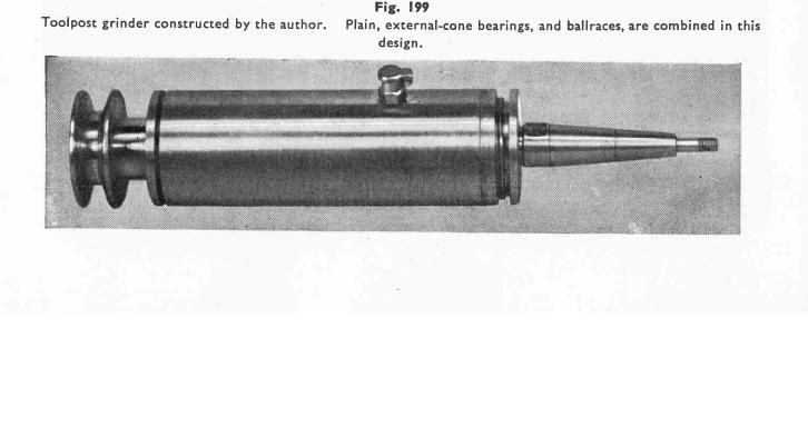
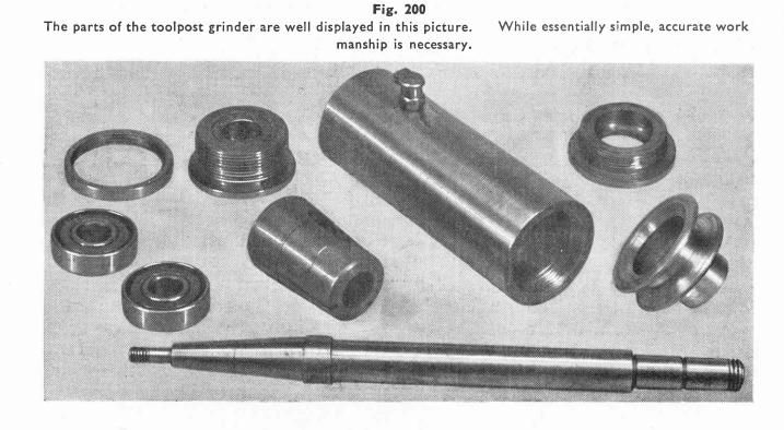
      In The Amateurs Lathe is a design for a grinding spindle.

      As far as I can see if you tighten up the pulley nut it will jam the spindle solid clamping the bearings and the pulley either side of the rear bearing cover, which is screwed into the body of the spindle.

      Am I misreading the drawings or just the first person to look at them properly?

      Neil

      #25625
      Neil Wyatt
      Moderator
        @neilwyatt
        #326880
        JasonB
        Moderator
          @jasonb

          I wonder if the pulley should have been shown partly threaded then you could use that to adjust preload and lock with the nut.

          #326881
          Mick B1
          Participant
            @mickb1

            Leonardo's tank wouldn't gone anywhere either.

            #326887
            Carl Wilson 4
            Participant
              @carlwilson4

              It’s on p84 in my copy. I can’t see where the driving feature is between the pulley and the shaft.

              Also agree that if tightened the nut will just nip the bearings up. If partially threaded the pulley would not set endfloat on the taper plain bearing because it would still just pull the shoulder up against the front of the forward most roller bearing.

              As drawn, unless I’m missing something, it won’t do anything.

              Edited By Carl Wilson 4 on 12/11/2017 21:23:54

              Edited By Carl Wilson 4 on 12/11/2017 21:24:36

              Edited By Carl Wilson 4 on 12/11/2017 21:25:34

              Edited By Carl Wilson 4 on 12/11/2017 21:28:39

              #326888
              Neil Wyatt
              Moderator
                @neilwyatt

                Maybe, but that would mean the pulley was running against the inside of detail 7, it would really need a thrust bearing before the pulley.

                I think detail 7 (the end plug) should be bored 0.750 right through so the pulley can directly bear on the inner race of the bearings giving positive location in both directions.

                If 7 is the part at top left of fig. 201, this might be right?

                Neil

                #326889
                Andrew Moyes 1
                Participant
                  @andrewmoyes1

                  The photo on p177 of my hardback copy shows the bore of the rear bearing to be larger than that of the front bearing i.e. different to the drawing. I think it’s a drawing error and the pulley should clamp up against the inner race.

                  Andrew

                  #326891
                  Carl Wilson 4
                  Participant
                    @carlwilson4

                    That aside, how does the pulley drive the shaft? There is no key or driving feature.

                    #326893
                    Mike Poole
                    Participant
                      @mikepoole82104

                      If that's the first time it's been noticed then that's 69 years, in the photo of the parts it looks as though it is bored through at the 0.750" diameter which would make sense to axially locate the shaft with the ball races by tightening the pulley against the bearings with the nut. I still think it is a great book though. Every dog is allowed one bite.

                      Mike

                      Should have refreshed before posting the same observations as others.

                      Edited By Mike Poole on 12/11/2017 22:01:00

                      #326903
                      Robbo
                      Participant
                        @robbo

                        Neil

                        Tomorrow I'll send you a pdf of the original article on the grinding attachment, from "The Model Mechanic" which may help.

                        Published August 1946. You probably remember that Lawrence Sparey was the Editor, though the article was credited to "F.Williams" – probably a nom de plume.


                        Edited By Robbo on 12/11/2017 23:16:11

                        #326905
                        Carl Wilson 4
                        Participant
                          @carlwilson4

                          Neil if you solve the mystery you could write it up for Mew!?

                          #326909
                          Neil Wyatt
                          Moderator
                            @neilwyatt

                            Well if Robbo's PDF solves it, I will share!

                            #326930
                            Ian S C
                            Participant
                              @iansc

                              What is the "slight undercut" indicated on the RH end of the shaft, it doesn't appear to be for run out of the thread. On the drawing in my book the assembled diagram looks as though the groove appears filled with metal of the pulley?

                              Ian S C

                              #326932
                              Ady1
                              Participant
                                @ady1

                                Curious, I was thinking about this kinda thing this morning

                                If you want a simple reliable strong "headstock type system" then have bearings in the middle for the shaft to run on and put a needle/roller bearing on each end to handle the thrust loading requirements

                                Preload lightly

                                edit: The ease with which we can get bearings nowadays makes things much simpler

                                edit 2: The original article probbly expected you to use a basic common sense 1946 system like a thrust washer

                                grinder1.jpg

                                grinder2.jpg

                                Edited By Ady1 on 13/11/2017 09:56:42

                                #326948
                                Carl Wilson 4
                                Participant
                                  @carlwilson4

                                  I’ve been looking at that photo in the book and thanks for posting it so others can see. There is no positive driving feature on the shaft.

                                  I agree with Ian in the drawing in my book it looks like the little undercut has the pulley metal in it. Can’t be right.

                                  Edited By Carl Wilson 4 on 13/11/2017 11:35:58

                                  #326953
                                  Clive Foster
                                  Participant
                                    @clivefoster55965

                                    Looking at my 1960, third edition, of the Amateurs lathe there are considerable discrepancies between the drawings and the pictures of Mr Spareys' personal version which are the same as in the previous post from Ady1.

                                    In particular the pulley on his has a fairly long stand off between it and the cap, part no 7 on the drawings, whilst the drawings show the pulley pulled back very close to the body with the stand off inside the cap. Looking at the cap in the pictures it appears to have a recess for, presumably, a deep felt washer to help keep grit out whilst the one in the drawings has a groove for a much shallower one. As drawn part 7 will jam up the bearings nicely and the pulley will come up tight against the cap both inside and outside too if everything is made exact to size.

                                    Looks like the pulley and end cap drawings have been somewhat codged up during an attempt to make the device simpler for the home shop man to make. Perhaps the intention was to make the two felt dust excluder rings the same thickness.  The screw on rather than integral wheel carrier taper might also be considered an appropriate simplification, but thats something that I'd disagree with.

                                    On deeper investigation the whole design is, to put it bluntly, crap for the assumed target audience. Complex in the wrong places. At the original 1948 printing date there is pretty much no way any ordinary Model Engineer would have a hope of making the thing to a sufficiently good standard with the sort of lathe typical of the time. A Southbend or Atlas would perhaps be up for it but Drummond, Portass, Zyto et al. Ferrgedditt. Heck would Home Shop Guy even have a micrometer then. Even by 1960 when Myford 7, Boxford et were making some penetration it wouldn't be a straightforward job. There are some fairly obvious simplifications that would make life much easier. Looking at the pictures the original is actually easier to do.

                                    As for making a small grinding wheel from a broken bigger one as suggested on page 180. Even for less safety conscious era thats flat out irresponsible. Maybe Experienced Man can repurpose a broken wheel. But Home Shop Harry taking on a bit cadged off mate in t'pub! Um.

                                    I suspect the reason that no-one has noticed the error is that no-one ever built the thing. Which does raise the question of what percentage of the lovingly crafted drawings pictured in the ME / HSM books and publications over the years actually ever get made. I certainly have never made anything to drawing. Read the articles, nicked ideas and filed off the serial numbers so folk think "gosh, he's clever" (how wrong can you be!). Yup. But make to drawing. Nope.

                                    Clive.

                                    Edited By Clive Foster on 13/11/2017 11:57:32

                                    Edited By Clive Foster on 13/11/2017 11:58:57

                                    #326954
                                    Carl Wilson 4
                                    Participant
                                      @carlwilson4

                                      Glad someone said it. It’s a great book full of sage wisdom. But that drawing is nonsense.

                                      #326957
                                      Bazyle
                                      Participant
                                        @bazyle

                                        What's the fat tube in the middle of the picture. Looks like a bearing spacer to me – setting the gap between the two inner faces of the smaller part of the bearing. Same on some car wheels except they have pick off shims to adjust the endfloat. A model engineer would test and turn a tad off.

                                        #326958
                                        Tim Stevens
                                        Participant
                                          @timstevens64731

                                          Surely you are not saying that someone actually goes out and makes all those wonderful complex models in ME?

                                          Tim

                                          #326961
                                          Clive Foster
                                          Participant
                                            @clivefoster55965

                                            Bazyle

                                            Fat tube is a classic taper adjustable double plain bearing. In the photo you can't readily see the adjustment slits which let it compress slightly when pushed down the taper so setting exactly the right clearance. Just visible if you know they are there.

                                            Lord knows how Home Shop Harry is supposed to get the adjustment taper in the body concentric with the ball bearing recesses. Not to mention getting the bearing bore and external taper similarly concentric. Talking sub tenths thou tolerances here if its all gonna go together and turn. I'm a fair machinist on a good day, and my Smart & Brown 1024 is very accurate, but I'm none to sure if I could turn that lot out to drawings and have it work on assembly.

                                            Usual practice in that era would to use a "magneto" bearing, i.e. separate cup cone and ball race, at each end in simple bored tube. Fit an appropriate spacer to keep the cups apart. Use a nice fat shaft to minimise whirl and call it good.

                                            For this sort of device grinding loads are small so no need for mega bearings and accuracy on a lathe cross slide a couple of tenths at best.

                                            Clive.

                                            Edited By Clive Foster on 13/11/2017 13:07:24

                                            #326963
                                            Bazyle
                                            Participant
                                              @bazyle

                                              Bah lost my post. start again. Ignore parts of my previous post.

                                              The ring top left in the photo is a locking ring for the front end cap as seen in the completed unit. The rear bearing is pushed home against the seating that I assume is in the body and locked with the endcap. The inner fat tube is made to drawing length and assembled with pulley etc locked hard with the end nut. No lock nut needed as it is just tightened fully. The inner assembly is fixed length not adjustable.
                                              The front bearing outer is advanced inwards (but must be free to slide without wedging in and must not hit a seat in the body) until the endfloat is taken up then the endcap is locked with the ring first mentioned.

                                              The spindle is turned between centres on your round bed Drummond and used as a mandrel for getting the ends of the spacer true. If your 3 jaw is a bit unsteady for getting the bores in the body parallel to one another do the final bore with a between centres boring bar. After finishing one end you switch the bar on its centres end for end so the second end is exactly the same bore.

                                              Actually it is a better design in this respect to the Quorn.

                                              #326964
                                              Carl Wilson 4
                                              Participant
                                                @carlwilson4

                                                All of that above may well be the case.

                                                There’s still no driving feature.

                                                #326965
                                                Bazyle
                                                Participant
                                                  @bazyle

                                                  Clive you got me there. Not familiar with that at all.

                                                  #326967
                                                  Neil Wyatt
                                                  Moderator
                                                    @neilwyatt

                                                    I think (a) the end cap top right is bored through 3/4" full and (b) (looking at the assembled picture) there has to be a tubular extension spacer between pulley and the inner race, otherwise the pulley would be closer to the body.

                                                    I suspect the spacer was added when it transpired the pulley 'nose' wasn't quite long enough.

                                                    The position of the spindle is then fixed by the inner bearings being squeezed together between the step on the spindle and the missing spacer. This also preloads the bearings.

                                                    The front plain bearing is then adjusted with the front cap and its locking ring but it has no role in locking bearings or setting the position of the spindle.

                                                    Hugely over-complex and very demanding to make for a grinding spindle.

                                                    #326968
                                                    Jeff Dayman
                                                    Participant
                                                      @jeffdayman43397

                                                      I think you are right Neil. It coul probably be made to work, but if someone wanted a grinding spindle it would probably be wise to look at Harprit Sandhu's spindles book in the "workshop Practice" series. Much more practical to make one of those.

                                                    Viewing 25 posts - 1 through 25 (of 68 total)
                                                    • Please log in to reply to this topic. Registering is free and easy using the links on the menu at the top of this page.

                                                    Latest Replies

                                                    Home Forums General Questions Topics

                                                    Viewing 25 topics - 1 through 25 (of 25 total)
                                                    Viewing 25 topics - 1 through 25 (of 25 total)

                                                    View full reply list.