Ball screws & drive slots?

Advert

Ball screws & drive slots?

Home Forums Manual machine tools Ball screws & drive slots?

Viewing 11 posts - 1 through 11 (of 11 total)
  • Author
    Posts
  • #12514
    IanT
    Participant
      @iant

      Possible Atlas MF Mill backlash solutions

      Advert
      #198010
      IanT
      Participant
        @iant

        Saw a Tom Senior mill that has had ball screws fitted yesterday, still a manual machine but now very smooth and no noticeable backlash.

        My thoughts turned to my elderly Atlas MF Horizontal mill, that has lots of backlash in all axis. I'd been thinking about making new PB nuts, involving also making acme taps etc. From curiosity, I looked at the cost of ball screws just now. Some ball screw & nut combinations direct from China seem almost affordable (assuming they are not really junk) and might just do for a manual machine . I then thought on about what other problems could arise and immediately realised that the Atlas table has a power feed, which is enabled by a long slot milled in the acme feed screw. A fixed drive gear engages with this slot to provide power feed as the table moves up and down.

        The slot clearly doesn't bother the existing PB acme feed nut but I'd have to mill a similar slot in any new ball screw to retain the exiting table feed. Would this cause damage to the ball nut or are the balls retained in such a way they would pass over the slot safely

        Any views – or anyone done something similar.

        Regards,

        IanT

        #198013
        Bazyle
        Participant
          @bazyle

          Is the drive dog/gear on the shaft next to the feed nut? They often are. Perhaps the modification can mount the ball nut on the gear rather than be fixed.

          #198014
          Muzzer
          Participant
            @muzzer

            Hi IanT

            I bought a set of 3 ball screws and nuts from a seller in China on AliXpress for my CNC conversion. They offer to machine the screws to your drawings for a few dollars extra which I took them up on. Having designed my own complete conversion in CAD, I was able to print out a set of PDF drawings which the seller used to make my set up from. This included my own keyways, threads etc and a variety of diameters and lengths. I was pleased to find that they were nicely machined and the dimensions were spot on. Definitely worth getting that done, rather than only getting half the job done and having to machine an unwieldy leadscrew yourself.

            My ballscrew conversion ballscrews retain the original Bridgeport-style endings but are extended to provide somewhere to mount the toothed belt pulleys. On the face of it, I could even reuse the Align AL-500 power feed unit but in fact I will be fitting this to the knee screw. My Z-axis conversion acts on the quill.

            The main fly in the ointment is that the ballnuts are somewhat larger than the original, especially if you opt for the double-length "backlash free" version.

            Murray

            #198019
            IanT
            Participant
              @iant

              Just trying to visualise it Bazyle.

              The keyed gear (which is on the left) sits in a slot that is part of the saddle & feed drive unit. A 'fork' moves another gear (from memory) in and out of engagement with it. But the keyed gear always revolves with the feed screw (because of the key) but can slide up and down it's length freely as the table moves. The feed nut is stationary, the body of the nut sitting in a hole in the centre of the saddle.

              So the gear always revolves with the feed screw but the nut is stationary with the feed screw revolving within it. So I'm not sure how the two would be connected but I'm probably missing something blindingly obvious.

              If a ball nut can work with a drive slot in the ball screw, then the ball nut just has to be held in/attached to something similar to the body of the existing PB nut. Apart from machining the ends of the ball screw (to fit the handles etc ) and that would be about it. The Y axis has no slot to worry about, so should be simpler.

              IanT

              #198024
              Les Jones 1
              Participant
                @lesjones1

                Hi Ian,
                If my understanding of Bazyle's suggestion is correct then the idea it to rotate the nut on the ballscrew and the screw itself would be stationary. One other point to remember is that the pitch of ball screws is normally coarser than a normal leadscrew so the resolution of the graduations on the hand wheels would be less. (Or you would have to make the graduations very close together.)

                Les.

                #198027
                Michael Gilligan
                Participant
                  @michaelgilligan61133

                  Posted by IanT on 26/07/2015 12:43:17:

                  … I'd have to mill a similar slot in any new ball screw to retain the exiting table feed. Would this cause damage to the ball nut or are the balls retained in such a way they would pass over the slot safely

                  Any views –

                  .

                  Ian … In my very limited experience, the balls are not restrained 'radially' in the nut [i.e. they are located by the screw], and would most likely drop into the slot.

                  [ Happy to be corrected by those who know better ]

                  MichaelG.

                  #198028
                  IanT
                  Participant
                    @iant

                    Ah, thanks Les – I thought I might be missing something.

                    Bazyle, I'm not sure there would be room to do this in the existing unit without major surgery but there may be another way to fit something similar. I'll have to strip it down to see what room is actually available & where..

                    I like the sound of getting the screws machined to size Murray. If the cost was reasonable, that would make things very much simpler. I assume that the keyways you mention are in the end of the feed screw (for securing handles etc) and not along the body (e.g. main length) of the ball screw?

                    Regards,

                    IanT

                    #198033
                    Michael Gilligan
                    Participant
                      @michaelgilligan61133

                      Ian,

                      Reference my previous post … I believe this is typical.

                      MichaelG.

                      #198043
                      IanT
                      Participant
                        @iant

                        OK thanks Michael – I thought that might be the problem.

                        That might rule this out as a (simple?) fix for the MF but I quite liked the idea of sending a CAD PDF design spec off to China for the custom ball screw set – and I have an X-Y co-ordinate table that might be suitable for some experimentation with steppers etc. Joins a long list though…

                        Thanks everyone.

                        IanT

                        #198045
                        Muzzer
                        Participant
                          @muzzer

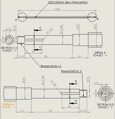
                          IanT – yes, just at the ends.This is from one of the drawings (for the X-axis). I think I paid $10 for the machining of the X and Y balllscrews. Can't recall if that was each or total but it was a bargain either way. You can't really machine keyways where the ball threads are.

                          I made a transfer arbor for my Z-axis ballscrew which I bought a few months before the X and Y so I could machine the ends myself. I also had to machine down the hardened flange on the Z-axis ballscrew. If you need to remove the ballnut, it could be tricky with some designs, so you should consider how to make and use one of these arbors at the design stage. I'm not planning to remove the X and Y ballnuts at this stage but that may change….

                          Unless you buy from the US, ballscrews tend to be metric and generally come in 12, 16, 20, 25 and 32mm diameters. The most common pitches are 4, 5 and 10mm, although there are larger ones if you look around. 5mm is the same as the original pitch on my metric Bridgeport clone and I could see no obvious reason to change it. I also downsized from 32mm acme thread to a 25mm ballscrew. If you look at the load specs, 25mm should be more than adequate.

                          BTW, if you are made of money, you could order from Misumi who make configurable ballscrews (and many other components). You can customise the design, download the resulting CAD file and get it made and delivered. No, I'm not made of money but it's an intriguing business.

                          Murray

                          X-axis ballscrew drg

                        Viewing 11 posts - 1 through 11 (of 11 total)
                        • Please log in to reply to this topic. Registering is free and easy using the links on the menu at the top of this page.

                        Advert

                        Latest Replies

                        Home Forums Manual machine tools Topics

                        Viewing 25 topics - 1 through 25 (of 25 total)
                        Viewing 25 topics - 1 through 25 (of 25 total)

                        View full reply list.

                        Advert

                        Newsletter Sign-up