Thanks for your ongoing support John, especially the link.
Your mention of torque variation and its effect on the behaviour of (any) escapement, is most valid. I’d always presumed that the time period of a pendulum (and spring/balance wheel) was a constant. This anomaly became obvious while I watched mine as it came close to running out of puff. With less torque, it was running faster, but that also seemed to relate to the mark/space ratio.
Against the drift of too many Senior’s Moments, and a similarly elderly CAD package, which still grabs my attention, I’ll try to get to grips with the contents of that link John.
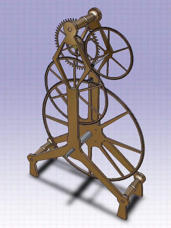
To be perfectly honest, as my ailing friend in a nursing home still asserts, this level of investigation has come as something of an unexpected challenge. None of which, I had a clue about while building my one and only clock back in the 70’s. The teeth on the wheels of my version of John Stevens’ skeleton clock are vaguely similar to an involute. In contrast, and though I say it myself, my lantern pinions look quite respectable.
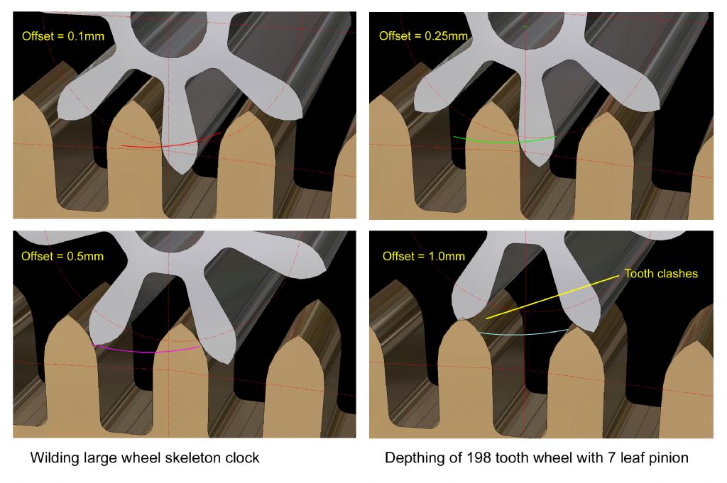
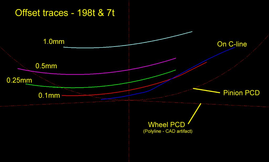
Having, over the past few weeks completed the (depthing) exercise including the other pair of (198/7) wheel/pinion ‘gears’, I still feel the urge to offer it here. It just needs to be in a presentable form.
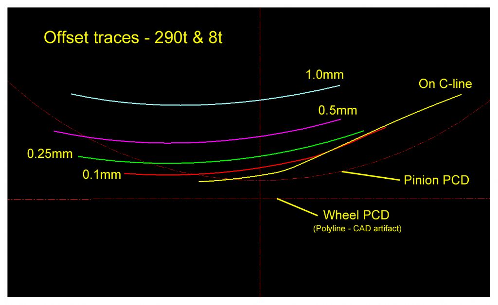
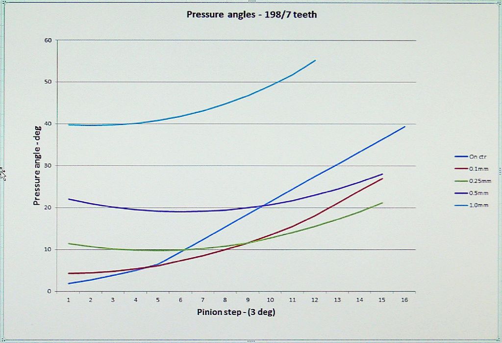
What I wasn’t expecting was this rather odd set of pressure-angle curves.

It was surprising to see straight lines and a comparatively sudden change of direction, not to mention the cross-overs. So, I laboriously repeated the complete exercise with greater accuracy. This time, any errors I had made were likely to be ‘accurate’ to several decimal places.
Sure enough, the (sudden?) shift from a smooth curve to a straight line matched where the point of contact changed from the pinion radius contacting the wheel flank to wheel radius contacting the pinion flank.
Sam 
Sam Stones.


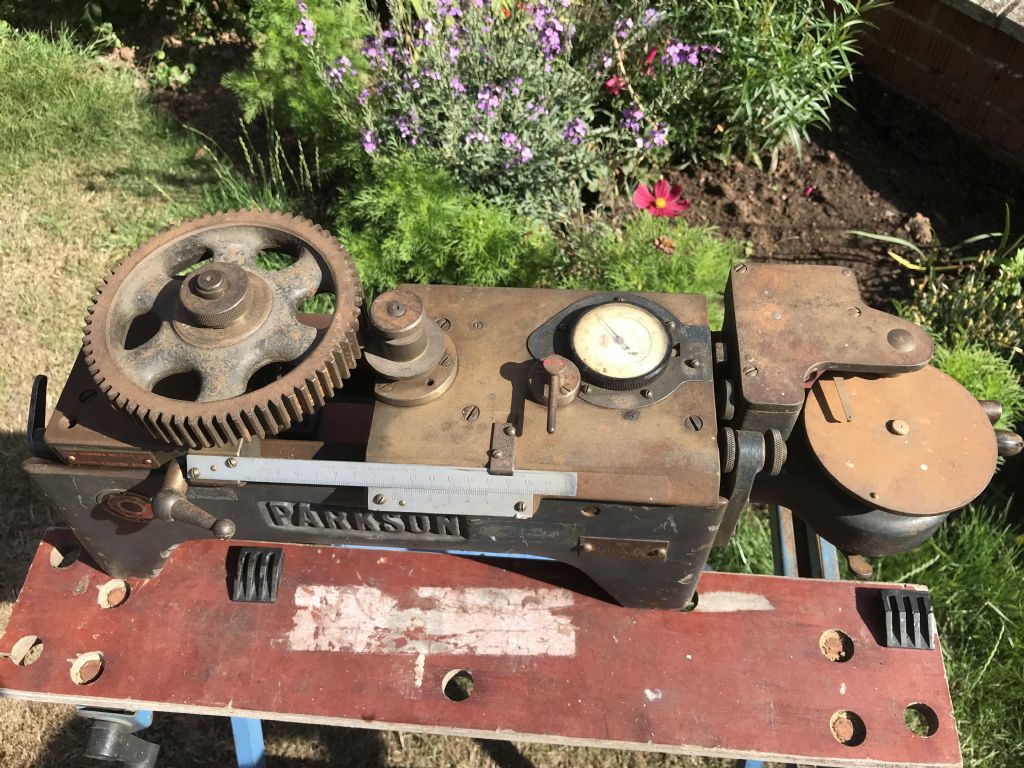
 and it was used, I believe, as a Merlin supercharger drive gear tester. The 'Old Boy' told me that the company did Government contract work for Rolls during the war and this was one of the tools that had lain about for years under a bench. It works beautifully still – the clock is graduated in 1/10000ths – I have a video of it with a couple of close ratio motorcycle gears on it being checked for 'depth' and 'run out'. Now I know why they were so harsh! I haven't mastered how to post video's yet! There are some more photo's of the tool in my album. The plant reference paint markings are pure artistry. You will also see it is a Parkson make, from memory Parkson took over the Sunderland Gear business in the 1930's which ties in with the quoted history.