Wiring for Parvalux Geared Motor

Advert

Wiring for Parvalux Geared Motor

Home Forums Help and Assistance! (Offered or Wanted) Wiring for Parvalux Geared Motor

Viewing 16 posts - 26 through 41 (of 41 total)
  • Author
    Posts
  • #516844
    Oily Rag
    Participant
      @oilyrag

      Brian,

      On reading your post I went to have a look at one of my Parvalux motors which runs a 'Scotchbrite' mop. I have several of the fractional hp motors with gearboxes, unfortunately not to hand at the moment.

      The 'mop' motor is a 240V 50Hz single phase 2800 rpm motor with cap start. The wires within the junction box are, from the motor 2 red and 2 white, the feed into the junction box from the mains is the normal blue, brown, and the earth yellow/green. the capacitor is external and is a 240VAC 50/60Hz 10uFd item.

      The connections are as follows:

      Mains Blue to White, Mains Brown to Red, whilst the remaining Red and White internal wires are joined together. This leads me to assume it is a 2 pole motor and the 2 poles are in series by way of the Red/White connector. The capacitor sits across the power 'inlet' i.e one side to the mains blue and one on the mains brown. This makes me think it is a cap start / cap run system. There is however a centrifugal 'switch' which can be heard to click in as the motor slows down when switched off. The mains earth connection is grounded to the motor body by a screw inside the junction box.

      With your 2 smaller wires I wonder if these are 'centrifugal switch' connections for taking the cap out of circuit. hence i would expect them to be wired in one side to the cap and one side to one of the 'infeeds' from the mains. This would presumably make it a cap start only motor.

      I will dig out the gearbox motors to see if they are anything like your wiring – from memory they are 1/16hp and the gearboxes give a 12rpm speed. I have another motor without gearbox which is similar to the above but 1/8th hp and is fitted with a 4uFd capacitor.

      Can you detail your motor parameters, and a photograph would also help. I would be interested what hp rating it is (or Wattage), motor rpm, and whether it has an external cap.

      A Happy (and Healthy) New Year to all,

      Martin

      Advert
      #516847
      Michael Gilligan
      Participant
        @michaelgilligan61133
        Posted by Brian Pritchard on 01/01/2021 20:48:03:

        That post was in 2018 and I have contacted them since without any help.

        Brian

        .

        My apologies blush

        MichaelG.

        .

        I don’t suppose pdf p19 [numbered page 17] of this would be any help:

        https://www.parvalux.com/media/wysiwyg/Resources/Catalogues/Parvalux_-_AC_Catalogue.pdf


        Edited By Michael Gilligan on 01/01/2021 21:52:47

        #516861
        Nicholas Farr
        Participant
          @nicholasfarr14254

          Hi Brian, has it got a brake fitted to it? if so the two thin wires could be for operating the brake and if there is no resistance between them the brake has gone open circuit, if there is no brake fitted, then it is probably an internal fuse. The two white and the black would be the supply, the black going to live, one white to neutral and one side of the capacitor and the other white going to the other side of the capacitor and if it goes the wrong way, swap the two white wires over. It may help if you could give the model number.

          Regards Nick.

          Edited By Nicholas Farr on 01/01/2021 22:02:07

          #516868
          Frances IoM
          Participant
            @francesiom58905

            Michael – great find – my small motors are all SD type as I suspect is Brian’s – their figure confirms my wiring and my 4microFarad is mid range for either the 2 or 4 pole but if Brian knows the model or power then he can adjust the capacitor as appropriate tho these are usually not specified to better than +/- 25%

            Edited By Frances IoM on 01/01/2021 22:21:09

            #516913
            Brian Pritchard
            Participant
              @brianpritchard66881

              Thanks for the replies. I have posted two photos of the motor in Brian Pritchard's Album.

              The motor just stopped working. I removed the motor for checking, didn't photograph the connections. I was given another motor but it was DC so no use. I wanted to check the motor with a new capacitor but, of course, could not remember the connections.

              These are the details from the motor.

              ST132

              230/240V, Condenser 5 mF, 1 phase, 100 rpm Ref: SD 14HD 5028/TROP.

              I am not aware that it has a brake perhaps the black wire are for an internal fuse as suggested.

              I hope I have answered all the questions, I am ready to tear my hair out, if only I had any, The compressor motor went bang a couple of months ago and the milling machine went bang yesterday. I am thinking of trying crochet, it is cleaner and less stressful.

              Happy New Year to all.

              Brian

              #516927
              John Haine
              Participant
                @johnhaine32865

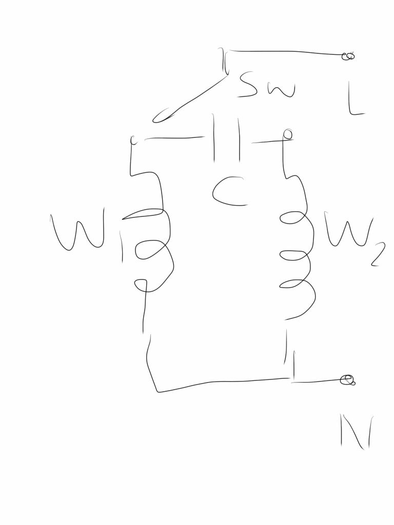
                I think this might help, based on the connections to the motor on my Quorn.

                image.jpeg

                Ignore the thin black wires. The thick black wire will correspond to the N (neutral) connection and goes to the common connection of the two windings. The tops of the two windings will be the two white wires, they go across the capacitor. The live L connection goes to one end or the other of the capacitor depending on switch position, for reversing.

                #516929
                Swarf, Mostly!
                Participant
                  @swarfmostly

                  Hi there, Brian,

                  Suffering three motor failures is a bitter portion! I can't add anything to the technical advice you have already received from other members.

                  However, I am moved to offer you words of encouragement:

                  Thanks to this forum, you are not on your own. Hang in there and keep trying! These things can usually be fixed. Remember, tenacity tells.

                  Best regards,

                  Swarf, Mostly!

                  #516976
                  Nicholas Farr
                  Participant
                    @nicholasfarr14254

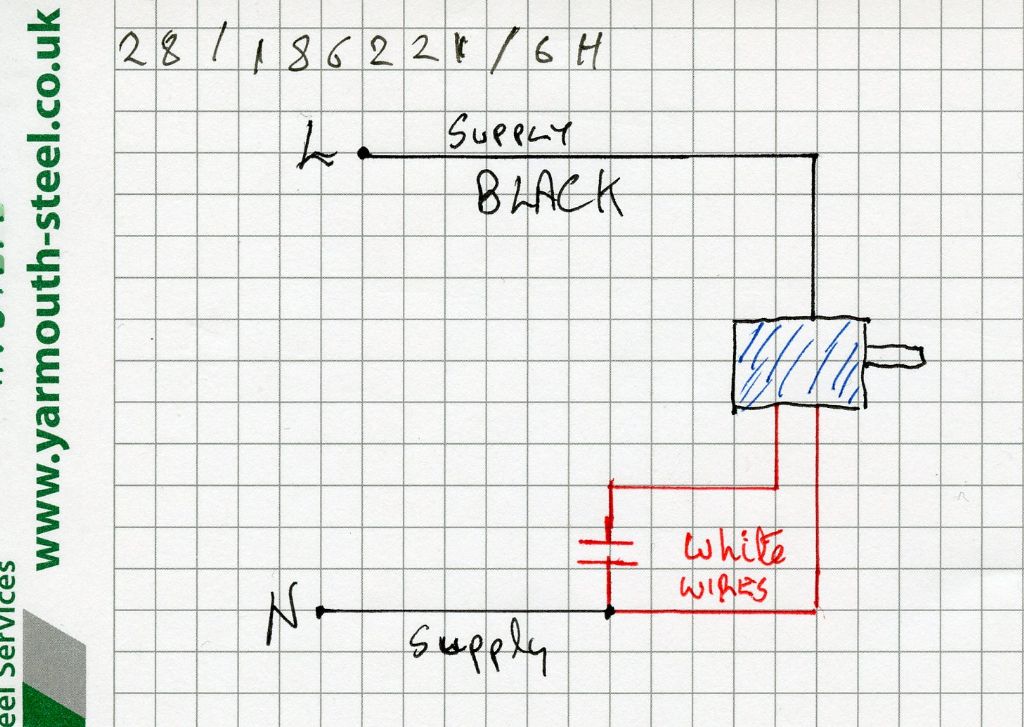
                    Hi, this is the wiring diagram printed on the capacitor for my Parvalux motor, and although I've marked L and N they are not marked on the capacitor, but seeing how it's AC it shouldn't matter which one is Live and which one is Neutral. Mine works fine with it wired as shown, (and I know the white wires look red, but I don't have a white pen) smile The number on the sketch is the model number of mine.

                    wiring001.jpg

                    Regards Nick.

                    #516987
                    peak4
                    Participant
                      @peak4

                      Hard to find info an a Parvalux SD14 HD family
                      My guess is that the two thin blacks are for either thermal protection or speed sensing

                      However see Appendix 2 Fig 1 of this document P326
                      From P 120
                      In the first configuration a mains operated alternating current (a.c.) motor (Parvalux Limited, SD14 supplied by Super Power Limited, 220-240V a.c., full load RPM 85, HP t~r, TORQUE 19 lb. in.) was mounted on the chassis side plate. The circuit diagram for this configuration was as shown in Appendix 2, Figure 1.

                      It looks like capacitor across whites, Neutral to single black, Live to one of the whites only, depending on which direction you want it to run.

                      Bill

                      #516995
                      Les Jones 1
                      Participant
                        @lesjones1

                        I think John's and Nick's diagrams are probably correct. They are both functionally the same. The fact that the mains polarity is shown different does not matter. (Either way is OK.) If the motor rotates in the wrong direction then swap the power wire to the other white wire. (That is the Live in John's diagram. The neutral in Nicks diagram.) If you want to know what the thin black wires are then you will have to dismantle the motor. I can see three possibilities. They could go to a thermal fuse, A thermistor for monitoring the temperature. (This is not very likely on an old motor,) They may also may go to a centrifugal switch which disconnects the start winding when the motor gets up to speed. If it is a centrifugal switch it is faulty as it should measure almost zero ohms when the motor is stopped.
                        You could do a rough test of the capacitor by connecting it in series with a 60 or 100 watt incandescent lamp. (If you still have any of them.) The lamp should light but not quite as bright as when connected directly to the mains.

                        Les.

                        #517081
                        peak4
                        Participant
                          @peak4
                          Posted by Les Jones 1 on 02/01/2021 14:35:56:

                          I think John's and Nick's diagrams are probably correct. …………………………

                          Les.

                          Also ties up with the one I found, but more importantly it also shows that Parvalux got it correct in their catalogue. devil

                          I've no idea how I missed Michael G's post linking to it, and even less idea why I failed to find that reference when I spent ages searching the Parvalux web site when I was wiring my own Quorn. blush

                          Bill

                          #517201
                          Brian Pritchard
                          Participant
                            @brianpritchard66881

                            Thanks for all the helpful replies. Using a lamp to test a capacitor is a new one on me, I will try it out. I also have the problem that if the RCD in the switchboard drops out, all sockets in the house drop out and if the boss is watching telly I become a victim of domestic abuse!

                            Perhaps I should use a separate RCD adapter when testing motors?

                            Cheers

                            Brian

                            #522038
                            Brian Pritchard
                            Participant
                              @brianpritchard66881

                              The Saga continues. I decided to look inside the motor before attempting wiring up. I have posted three pictures of the coil in my album 'Parvalux Wiring'. There are two black wires going into the coil on one side and two white and One black on the other side.

                              Any further thoughts? What values of distance should I expect?

                              Thanks as usual.

                              I fixed my milling machine, it seem to be some swarf had got into the motor; it is now running OK. The compressor is next for investigation.

                              Brian

                              #522050
                              Emgee
                              Participant
                                @emgee

                                Brian

                                Connect as John Haine's sketch above but add some insulated sleeving over all of those wires as one of the white wires has a split in it, unless it is brittle.
                                For confirmation of connections schematic below, use the 3 lead capacitor and insulate the thin black wire.

                                Emgee

                                parvalux sd connections 230vac.jpg

                                #522054
                                Brian Pritchard
                                Participant
                                  @brianpritchard66881

                                  Thanks. Just out of interest what do the two thin black wire do?

                                  Brian

                                  #523848
                                  Brian Pritchard
                                  Participant
                                    @brianpritchard66881

                                    Thanks to all he helpful replies. The motor is now working. I think the problem, apart from the correct wiring, was the wires which are quite hard and cracking and caused a short. I have covered the wires with heat shrink and that seems to have solved the problem. It has taken me 2 years!

                                    The failed milling machine motor was caused by swarf getting into the motor. The compressor motor also had problems with wires shorting. It was tidied up and is now also working.

                                    So back to work creating large quantities of swarf and filling the junk box.

                                    Brian

                                  Viewing 16 posts - 26 through 41 (of 41 total)
                                  • Please log in to reply to this topic. Registering is free and easy using the links on the menu at the top of this page.

                                  Advert

                                  Latest Replies

                                  Viewing 25 topics - 1 through 25 (of 25 total)
                                  Viewing 25 topics - 1 through 25 (of 25 total)

                                  View full reply list.

                                  Advert

                                  Newsletter Sign-up