WARCO WM-250 lathe family and WM16 mill – 001

Advert

WARCO WM-250 lathe family and WM16 mill – 001

Home Forums Workshop Tools and Tooling WARCO WM-250 lathe family and WM16 mill – 001

  • This topic has 374 replies, 62 voices, and was last updated 6 July 2020 at 23:20 by Cabinet Enforcer.
Viewing 25 posts - 101 through 125 (of 375 total)
  • Author
    Posts
  • #124552
    JasonB
    Moderator
      @jasonb

      Backplates should always be turned in-situ to get them concentric to your spindle. Also make sure you put a mark on the backplate so it always goes back on the same way in much the same was as your 3-jaw is marked

      The three tapped holes in the backplate are probably on the correct PCD for the studs that go through the mounting flange, you will need to drill for suitable fixings to attach the chuck to the backplate. Best to counter bore from the rear of the backplate and screw into the chuck, that way the front is nice and clear with nothing to catch your hand or tools on.

      J

      Edited By JasonB on 14/07/2013 17:42:55

      Advert
      #124658
      mechman48
      Participant
        @mechman48

        Rik

        Was contemplating getting the same for mine; let's know how you get on, with write up & pics.

        For info; All Warco's BT tel. lines are down, had to get in touch via their website which have mobile phone #'s for contact at the mo'

        Re.duff Z axis integral DRO; my machine is just still in warranty.. explained fault etc. to after sales / spares dept.. replacement DRO on it's way as I write… result .. thumbs up

        George

        #124663
        mechman48
        Participant
          @mechman48

          Spent some time 'pottering ' last week, decided to make saddle stop for lathe, nothing specific in mind nor plans to hand, just a block of ally' 6mm SHCS, 6mm Hex bolt, & made up a brass knurled lock nut, set to with measuring,marking,drilling, milling & ended up with the following:

          saddle stop (4).jpg

          Milling ally block.

          saddle stop (5).jpg

          marked out ready for chain drilling.

          saddle stop (6).jpg

          Initial trial fit after cleaning up sides on mill, distance from inside of block to rack is only 5mm,not much for underneath grip,so go for side grip?

          saddle stop (9).jpg

          Ended up with this.. have since changed the ally lock nut to a larger brass knurled nut, the side fastening was decided on as the distance from the block to the saddle traverse rack only left me with 5mm which seemed a bit skimpy to grip with..so went for side locking with 6mm SHCS,after all it is only a simple stop for machining up to a shoulder so not looking for anything fancy..yet! no doubt some of you have made better, possibly better clamping arrangement..would be nice to see & maybe use to improve mine. My motto..KISS.. Keep It Simple Stupid. Have drawing if anyone interested as a basis.

          George

          Edited By mechman48 on 15/07/2013 22:31:42

          #124677
          john kennedy 1
          Participant
            @johnkennedy1

            I like that,must get round to making one. John

            #124724
            Rik Shaw
            Participant
              @rikshaw

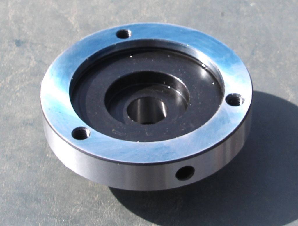
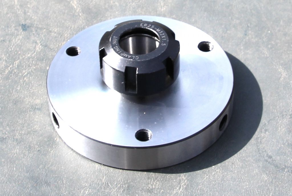
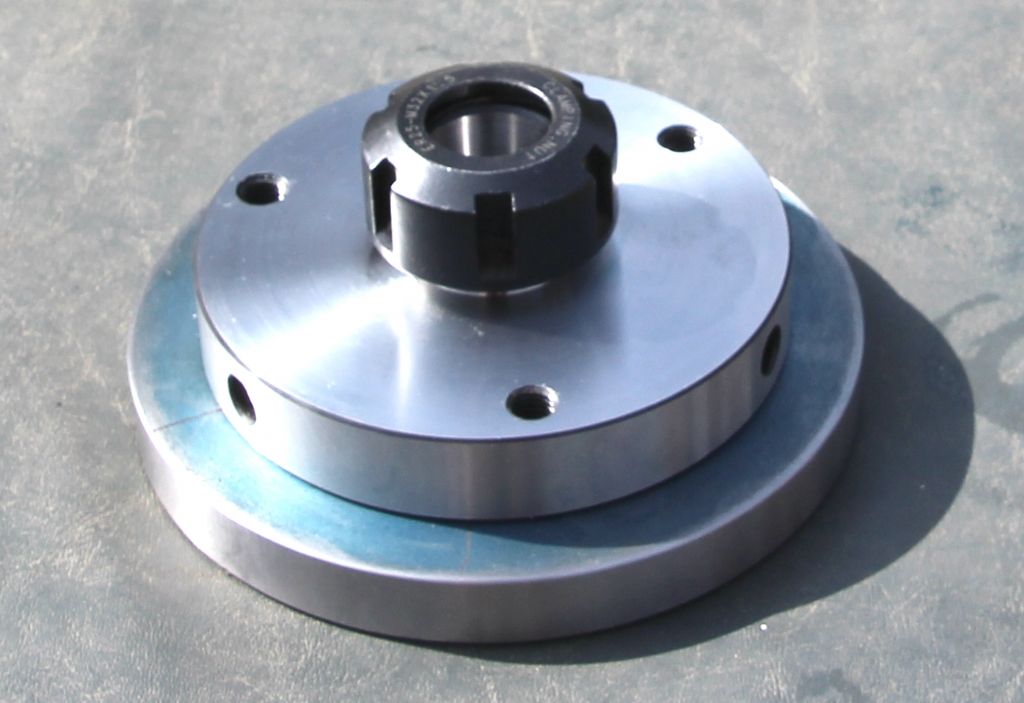
              George – pictures as requested re: new collet chuck. It's ER25 but only because my collet set was retained when I sold my mini lathe otherwise I would probably have gone for ER32.

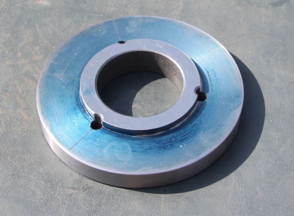
              The register on the backplate was simple enough to turn – around 180 R.P.M and with a cheapo carbide tipped tool. I had cut some short lengths of studding to hold the back plate to the lathe spindle but found that when I tried to attach the retaining nuts – the studding turned. The solution was to dispense with my studding and use the studs that hold the 3 jaw chuck. These have flats that will allow a small spanner to nip them up and prevent them turning (they did suffer a reduction in length during the machining process but nothing to worry about).

              All that remains to do now is to clamp the chuck to the backplate and using a 17/64 drill (a snug fit in the tapped hole), spot drill through the tapped holes in the chuck and mark start dimples on the back plate.

              Next, unclamp the backplate and using a tapping drill for 8mm and the dimples as guides, drill and tap the fixing holes in the backplate.

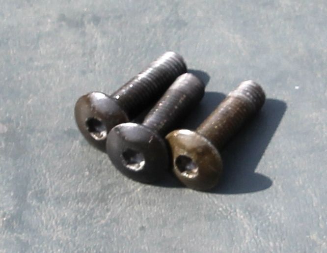
              I intend using the three 8mm socket head screws to hold the chuck in place so I am going to need to remove the threads from the shoulder down to where they just locate into the back plate. Effectively, the tapped holes in the chuck now become clearance holes for the relieved screws.

              I have chosen to use this method as I find it soooo difficult changing chucks with all that palaver with the nuts and washers to the rear of the spindle flange. I do not have particularly big hands but it can still take ages to get a chuck changed. Have tried various dodges but am still trying to figure out an easy way of getting round the problem. I have not turned down the diameter of the backplate to match the chuck because who knows when it might be adapted for something else. I am well aware that this job can be done in various ways – this is my way! I would add that I had to remove the spring steel lead screw cover in order to get the tool up to the backplate. If you do the same I would advise using thick gardening gloves – thrise I was sliced and blood gusheth.

              I unlocked the shop at 3.00 this afternoon with the intention of finishing the job but inside the mercury stood at 109 Fahrenheit. A cold Chardonnay spritzer suddenly became far more enticing —— cheers!

              Rik

              back.jpgfront.jpgregister.jpgscrews.jpgtogether.jpg

              Edited By Rik Shaw on 16/07/2013 20:22:42

              #124751
              mechman48
              Participant
                @mechman48

                Rik

                Thanks for the write up & pics; same as you I have the ER25 set, again left over from earlier times.

                How did you remove the leadscrew cover..did you have to unwind it leaving the brackets on, or take it off all in one with the brackets as well ?

                G.

                #124780
                SteveW
                Participant
                  @stevew54046

                  I ditched the washers and now just use flanged nuts on the chuck. Possibly not what I should do but I have limited time and fiddling with washers and nuts not really what I want to spend my time doing.

                  Nuts came from Arceurotrade.

                  SteveW

                  #124901
                  Rik Shaw
                  Participant
                    @rikshaw

                    Hello George – I left the bracket on and just pulled the spring off.

                    Having completed my collet set chuck machining and on testing it this morn was very disappointed to find a test piece was running out .0023". Have spent much of this morning investigating and have just found out why. The Chinese machinist had bored the backplate out oversize – not a lot – but enough to account for the runout.

                    I need to speak to Mr. WARCO about this but they have not been answering their phones for three days or so. If it IS a faulty line I would imagine the bossman must be very angry with the telephone company. Or is there a little more going on – or not????

                    Rik

                    #124917
                    JasonB
                    Moderator
                      @jasonb

                      RiK you may be better off buying a blank backplate or billet of cast iron then machine to fit, thats what I have done for the other chucks I have bought for my 280.

                      #124923
                      Rik Shaw
                      Participant
                        @rikshaw

                        Thanks for that Jason. I agree, you are better of doing the machining yourself.

                        Because the backplate  hole has been bored oversize WARCO have requested I return it FREEPOST for exchange. Before I do though, I am performing a small experiment. I have reduced the diameter of the collet chuck register on the back plate by about .003". I refitted the collet chuck with screws "nipped" and using a clock, tapped the now "floating" chuck into position a' la universal grinder. It runs now absolutely spot on.

                        My thinking is that as the "floating chuck" principle works well on a universal grinder because of the light "cuts" that are applied it might just work with the lighter duty work that is performed when using collets. Tomorrow I will use the largest of my ER25 collets (16mm) to hold a piece of steel and give it some welly. I am hoping the chuck stays put, I think it will. If it does then I'll not bother returning it.

                        Rik


                        Edited By Rik Shaw on 18/07/2013 17:59:02

                        #124931
                        JasonB
                        Moderator
                          @jasonb

                          The problem with that is you will need to true it up each time you change chucks as it will either be loose on the backplate spigot or loose on the spindle nose.

                          J

                          #124936
                          mechman48
                          Participant
                            @mechman48

                            Rik

                            Re your backplate machining..do you mean .023"..or .002" or do you have a digi /analogue clock that will read tenths of a thou'?

                            Check out their website; if they are still showing mobile #''s… ?

                            George.

                            #124957
                            Rik Shaw
                            Participant
                              @rikshaw

                              George – I mean .0023" – my clock/s read tentths of a .'thou. Jason – you are right but having operated a universal grinder for more years than I care to remember truing up a job before it is machined comes as second nature for me. Needless to say, I have not tried it yet, the workpiece may well shift under the pressure of the cut – it will have to wait till tomorow as I am tired and a little vacant (hammered!). I'll report back on the morrow. —— Rik

                              #124963
                              Crocadillopig
                              Participant
                                @crocadillopig

                                Hi Rik

                                The draw bar is used to secure and eject you 2 MT tooling. When I first tried the eject function I was a bit wary of the amount of effort that was required, I use an old fashion knuckle jointed brake adjuster on the square atop the draw bar with the spindle held under the head with the spanner provided in the tool kit . The draw bar is held captive by the threaded sleeve that fits over the top of it so that when you attempt to unscrew the draw bar whilst holding the spindle, it releases so far until the shoulder comes up against the underside of the top of the sleeve and then forces the tooling downwards, breaking the Morse Taper joint in the process. I have had my WM 16 since 2005 and have had very few problems apart from a duff potentiometer and and a sticky button on the vertical digital read out. I was rather dismayed though when I tried to adjust the fine feed control and discovered that the worm shaft is only supported at one end and therefore had damaged the brass worm wheel because of excessive play. Still usable but future expense. Hope this is of some use. (P.S. I am assuming that the system has not been modified in the intervening years since I purchased mine.)

                                Regards

                                Russ

                                #124997
                                Mark P.
                                Participant
                                  @markp

                                  Hi Russ, how do you adjust the fine feed?

                                  Mark P.

                                  #125003
                                  Crocadillopig
                                  Participant
                                    @crocadillopig

                                    Hi Mark

                                    When I said adjust I was referring to the fact that fine feed shaft had worked loose and become a sloppy fit in the head. To cure this I had to remove the coarse downfeed spider handle and associated flanges to get inside the head to see what was going on. That was when I discovered the damage the loose worm shaft had caused to the brass worm wheel and that there was no support for the end of the shaft. To tighten it up I levered the end of the shaft back towards the front face of the head whilst forcing the fine feed control knob up against the head face and tightening the securing grub screw (three hands required!). Unless I am missing something this is a very poor design and not fit for purpose as the knob/dial is all that holds the shaft in place and there is still a considerable amount of backlash.

                                    Russ

                                    #125009
                                    Rik Shaw
                                    Participant
                                      @rikshaw

                                      Have managed to do more work on my "floating" collet chuck today. Going for broke I removed a further .005" from the backplate chuck register then refitted the chuck with screws just nipped up. In with a collet and a 8mm dia. x 100mm piece of ground round tool steel as a test piece. Used a tenth clock and a lump of brass to tap the chuck/test piece true – zero deviation on the needle. Tightened chuck retaining screws. Clocked test piece again – no deviation.

                                      Now for the acid test, will the chuck shift or will it stay put. Replaced test piece with length of 12mm MS. Used first my own version of a diamond tangential tool holder to advance tool .125" and removed .250 from diameter for about 1" length. ( I love this tool and am glad I spent the time making it). Repeated this with a brazed carbide tip tool. Here, I put the test piece back in and took readings – no deviation.

                                      Repeated the above twice more – no deviations on clock.

                                      Conclusion: the job seems to be a good'un. I intend giving the setup a few more weeks work and if all seems OK I will not be returning the backplate to WARCO. (Phonewise, they are back "online" George).

                                      Rik

                                      #125023
                                      mechman48
                                      Participant
                                        @mechman48

                                        Info'

                                        Whether you have a WM180/250/280 I would double check the bolts holding the top slide to the crosslide as I have had to do repairs to my 250 V-F just recently. I was checking my compound slide alignment as I wasn't sure how good / accurate the fiducal line on the crosslide was in relation to the zero on the compound slide scale, so setting up a test bar & DTI I wound the compound to one end of its travel, zeroed the DTI & wound the compound back to the other end of its travel. Needless to say it didn't register 'zero'.>>

                                        After a couple of tries I got everything lined up to the test bar '0 – 0' along the compound slide travel,lightly nipped the clamping bolts to hold in place & checked the zero on the scale…no it didn't line up with the fiducal line on the saddle..well it is Chinese & their QC is s**t at the best of times. 'you gets what you pay for' blah, blah! it transpires that the fiducal line is not at 90* to the front edge of the saddle & correspondingly the zero (now set) does not match… am I too pendantic to ask for proper zero setting reference from manufacturers?

                                        So now I nips up the clamping bolts using the supplied open ended spanner… & you know when something doesn't feel right! …just didn't feel like they were tightening as they should… off come the nuts (now having upset my zero setting!  lo & behold… threads fxxx***… .oops, stripped… again typical example of Chinese crap metal, I would be loathe to class them in the basic EN1 class… mmmmm! I wonder if they could be EN1B (leaded?) which would make them 'softer' for easier machining..I diversify! I have ended up making BMS T nuts & using 8.8 bolts with a light skim off the head to allow the compound slide to rotate freely, reset the zero again & snugged the new bolts up… much better all round! will still have to centralise the fiducal line on the saddle…..

                                        comp.slide mods (1).jpg

                                        Honest! … only ever snuged them up with the spanner supplied in the kit, on the rare times I've moved the topslide.

                                        comp.slide mods (2).jpg

                                        T Nut Machined…(drilled & cut into 2 later)

                                        comp.slide mods (3).jpg

                                        Neat sliding fit…

                                        comp.slide mods (5).

                                        Bolt head skimmed …

                                        comp.slide mods (4).jpg

                                        All snugged up…

                                        comp.slide zero (1).jpg

                                        Zero set to test bar… fiducal line awry…

                                        comp.slide zero (3).jpg

                                        Difficult to see but the zero & fiducal line don't match, (toduit list !)

                                        So guys 'n' gals after my diatribe just a point to check on your machine/s, wouldn't like to think of the compound slide coming loose & moving when there's a cut going on due to some crappy bolts, maybe you've had this issue & resolved it? all the better, but for newbies & those upgrading or buying this type of lathe…

                                        Cheers thumbs up

                                        George

                                        Edited By mechman48 on 19/07/2013 19:58:11

                                        Edited By mechman48 on 19/07/2013 19:58:36

                                        #125042
                                        mechman48
                                        Participant
                                          @mechman48

                                          ps. pic 4 … must get that gib key sorted… it is what it looks like… s**t !

                                          G.

                                          #125254
                                          SteveW
                                          Participant
                                            @stevew54046

                                            I changed oil in my 250 feed gearbox today, Window nearly impossible to judge level on filling but I measured the drained oil (tad under 200 ml). Old oil looked like flat coke. A job I should have done a while ago and not chosen a day when it was 85 in the garage! Although the oil was pretty thin!

                                            SteveW

                                            #126609
                                            Rik Shaw
                                            Participant
                                              @rikshaw

                                              Size wise, WARCO will not recommend a rotary table any larger than an HV4 on my WM16 mill which at just 75mm dia. is trifling. Maybe it is because of height restrictions when the table is being used in the vertical position.

                                              If this is the case then maybe I’ll have to buy the HV4 as well an additional larger horizontal rotary table – maybe 6” – 8” dia. for some of the larger jobs I have in mind. Comments welcome.

                                              Rik

                                              #126615
                                              Thor 🇳🇴
                                              Participant
                                                @thor

                                                Hi Rik,

                                                I agree 75mm dia. rotary table is a bit small. I have a 100mm dia. and often find that too small, so I made a slightly larger one (120mm) after Dean's description. You could make your own in a size that suits you.

                                                As long as the rotary table is flat on the milling table your mill should handle a 150mm rotary table.

                                                Thor

                                                #126650
                                                JasonB
                                                Moderator
                                                  @jasonb
                                                  Posted by Rik Shaw on 10/08/2013 16:25:33:

                                                  Size wise, WARCO will not recommend a rotary table any larger than an HV4 on my WM16 mill which at just 75mm dia. is trifling.

                                                  The HV4 is 110mm dia not 75mm

                                                  #126702
                                                  Mark P.
                                                  Participant
                                                    @markp

                                                    I made an adaptor for my rotary table to take the faceplate from my WM250.

                                                    Mark P.

                                                    #126721
                                                    Crocadillopig
                                                    Participant
                                                      @crocadillopig

                                                      I use a 9" 'T slotted' faceplate from RDG (ref 210989) with a shortened adapter (ref 823AD Chuck) which incorporates a 2 morse taper although other locators are available. This fits my 4" vertex rotary table (ref 324958). This set up works for me on my WM16, although restricted in 'Y' axis, travel is still useable in 'X' and 'Z'. If you find it is not rigid enough for heftier cuts, support the overhang with a screw jack although I have never found the need

                                                      Russ

                                                    Viewing 25 posts - 101 through 125 (of 375 total)
                                                    • Please log in to reply to this topic. Registering is free and easy using the links on the menu at the top of this page.

                                                    Advert

                                                    Latest Replies

                                                    Viewing 25 topics - 1 through 25 (of 25 total)
                                                    Viewing 25 topics - 1 through 25 (of 25 total)

                                                    View full reply list.

                                                    Advert

                                                    Newsletter Sign-up