Warco A2F quill backlash – any pointers?

Advert

Warco A2F quill backlash – any pointers?

Home Forums Manual machine tools Warco A2F quill backlash – any pointers?

Viewing 15 posts - 1 through 15 (of 15 total)
  • Author
    Posts
  • #457994
    YouraT
    Participant
      @yourat

      Hi all.

      I have a Warco A2F milling machine, of 1999 vintage, so a later one without the feed gearbox (although it has an electrical power feed unit).

      I have some problems with quill feed backlash, which come from I think three places:

      – The rack/pinion combination that is attached to the quill rapid feed lever
      – The worm drive that's used for the fine feed arrangement
      – A poor fit on the keyway for the screw-in arrangement that's used for engaging the fine feed.

      The last two I think I can do something about – re-cut the keyway in the toothed collar so it's less sloppy on the key, and make an eccentric bush for the fine feed handwheel arbor so the meshing can be adjusted.

      I'm less sure about the rack arrangement though – I think there's damage to the rack on the quill itself, as at times there's a sudden drop of ~1mm when downfeeding, especially at the top of the travel – I can't easily adjust the meshing on that, and have not been able to get rid of this problem without the feel of the feed becoming very lumpy, which suggests to be excessive depthing of the rack/pinion combination and thus rapid wear in use.

      Has anyone any experience with these machines or the very similar ones out there and could make some suggestions? I think this problem has existed ever since I've had the machine, but it's only recently started to annoy me enough to do something about it….

      Thanks,

      Youra.

      Advert
      #13802
      YouraT
      Participant
        @yourat
        #458022
        Bazyle
        Participant
          @bazyle

          I think first of all you need to disassemble the quill to look at the state of the rack and its pinion. May just be a bit of swarf.

          #458140
          John P
          Participant
            @johnp77052

            Hi Youra.

            a2f quill lock.jpg
            I have an A2F from 1998 ,the backlash from the downfeed
            pinion to the quill on my machine is .031 inch so not so much different
            from your machine, it has always been like this from new.
            Part of the problem is that the weight of the quill is unsupported ,the
            return spring is on the pinion ,i altered my machine by fitting a loose pulley
            wheel on the pinion shaft and machining a slot into the quill body and
            using a thin stranded cable (1mm) routed it out the back of the head
            casting to a gas strut which lives within the hollow tube .
            This does require some extensive machining and modifications to
            some of the parts of the head.
            This worked well until the gas strut packed up ,a suitable spring
            would do the job just as well . I altered the quill lock to a two part
            aluminium part see photo that has a left and right hand thread so that it will
            release properly and can be adjusted to give a positive feel when
            down feeding.

            You can inspect the pinion and rack fairly easily just by removing
            the parts you have identified, the handle return spring is under the
            cover on the handle side care is needed when removing
            as the spring is under some tension make sure that you fit some
            packing on the table under the quill as it will drop when the pinion
            is removed ,check also that the quill locking pads are in the correct
            position when you reassemble as they can easily be put back in
            the wrong position and damage the quill.
            Some other photo's of this machine in the album.

            John

            #458697
            YouraT
            Participant
              @yourat

              Thanks guys – I'll take a look and report back.

              At first sight though, it seems the feed and clamp mechanisms have been extensively modified by a previous owner, so they don't look much like the drawings I've found for this machine.

              John – I notice in your CNC conversion album that you've used the external depth stop as the basis for the Z-Axis drive, rather than the original worm drive – was this for reasons of backlash in the worm arrangement and rack, or some other reason?

              Cheers,

              Youra.

              #458715
              John P
              Participant
                @johnp77052

                A2F 6.jpg
                Hi Youra.
                The external depth stop was the first thing that i got rid of ,a completely
                useless part ,as you are probably aware the down feed index dial reads
                in units that are nothing to do with reality so a digital readout is a must for
                one of these machines.
                The cnc drive attaches to the existing holes that are in the quill from the
                the depth stop part ,the head has to be removed to rebore the top and bottom
                lugs of the depth stop to suit the ball bearings for the lead screw.
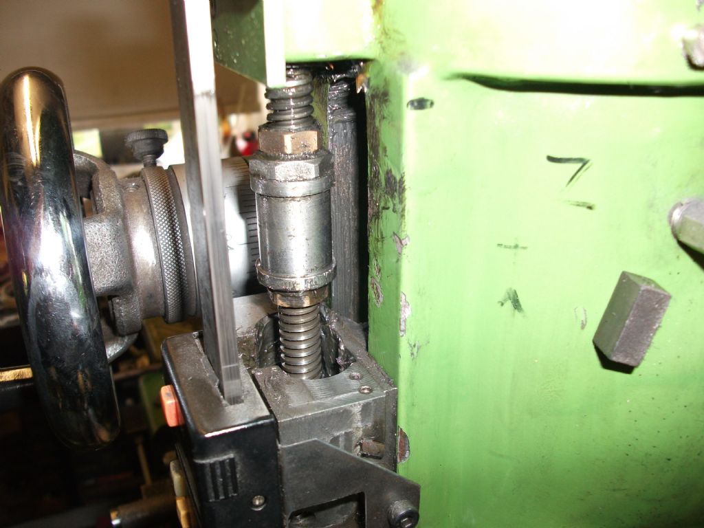
                As can be seen from the photo the lead screw is 7/16 x 10 TPI and has an anti
                backlash nut. The connection for the nut has a split clamp that mounts on a
                horizontal dovetail that connects to the quill ,to engage the nut the two halves
                are located around the nut and clamp with 2 m4 screws.The stepper motor
                sits within the original profile of the head ,as the machine is part manual with
                cnc the head can be used over at 90 deg and still get down close to the table
                if needed.
                I did consider trying to improve on the rather poor down feed problems
                associated with this machine but never use now the down feed handle for boring
                type applications .The machine has been in this part cnc state for about 14 years
                just using the Z axis for such things is easy to fit the 2 clamp screws and a control
                file to down feed and return to a set depth is much easier than using the handle.
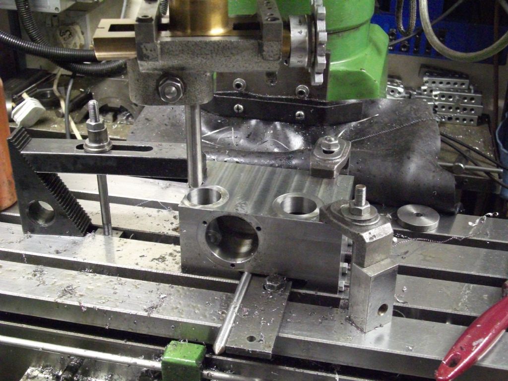
                As can be seen in the second photo boring down in this blind hole is easy and the
                zero backlash of this connection to the quill is worth having.

                John
                boring to set depth.jpg

                Edited By John Pace on 21/03/2020 20:24:27

                #458727
                Dave Halford
                Participant
                  @davehalford22513

                  Sticking quill?

                  #458996
                  YouraT
                  Participant
                    @yourat

                    Hi all.

                    Dave – no sadly – that would have been too simple – the quill resting on the table with the pinion removed goes up and down with the knee smoothly.

                    Bazyle – also unfortuneately not – actually remarkably clean in there! Cleaned and re-greased anyway though.

                    John – yes, the downfeed units make no sense – I also have a digital readout on the quill. I don't know if the depth stop is original or modified also (it's a 1mm pitch thread…) but it actually works reasonably well for my purposes – I get 0.03mm repeatability or so, according to the readout, in any case.

                    depth_stop.jpg

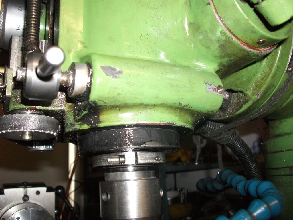
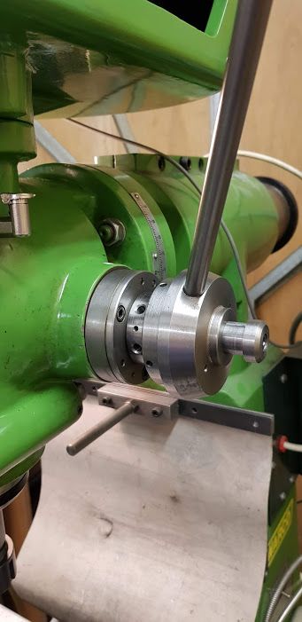
                    The quill rapid feed side of things is heavily modified with a whole new shaft, pinion (modified to 29 teeth), ball bearings at both ends and a new handle.

                    rapid_feed.jpg

                    I've been able to adjust things to improve on the performance from the fine feed worm wheel, and I now only get unexpected movements of around 0.3mm, but I think with judicious use of the depth stop I should be able to live with that, and certainly not use the rapid feed for anything other than drilling (which feels lumpy, but will do). I might beef up the depth stop rapid movement arrangement though – I'm not sure they will last.

                    Long term a counterweight / gas strut and something like your arrangement based around the location of the depth stop seems very attractive – I'm a little limited in my ability to take the machine apart at the moment though…

                    Cheers,

                    Youra.

                    #459356
                    elanman
                    Participant
                      @elanman

                      Hi,

                      I have a 1992 A1S which has the same or very similar vertical head.

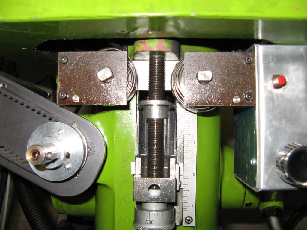
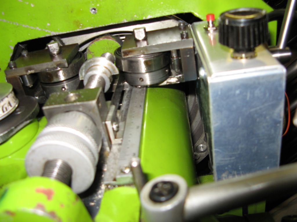
                      I did not like the backlash or the garden gate type return spring. So I fitted two clock type coil spring that pull the quill upwards by the stop block. The springs rotate a shaft that pulls on some shim SS to pull the quill upwards. This removes the backlash and gives a lighter feel when drilling. I also have down feed for boring holes.

                      I'll try to post some pics to give you more idea.

                      img_0093.jpg


                      img_0096.jpg

                      img_0097.jpg

                      Cheers

                      John

                      Edited By elanman on 24/03/2020 17:37:25

                      #459402
                      YouraT
                      Participant
                        @yourat

                        John,

                        Thanks for that – it does look a lot simpler to implement than the gas strut arrangement.

                        Something like one or two of these:
                        https://springcompany.com/products/constant-force-springs
                        would do perhaps… Perhaps I won't even need the extra shaft and SS shim in your setup..?

                        I'll take the machine apart again shortly to check the weight of the quill to work out what might fit – you don't perchance remember what the weight is (even approx…)?

                        Many thanks,

                        Youra.

                        #459576
                        elanman
                        Participant
                          @elanman

                          Youra,

                          Thanks for the link, I've not seen those before.

                          Cheers

                          John

                          #460195
                          YouraT
                          Participant
                            @yourat

                            Hi all.

                            So – I make the weight of the quill around 8kgs – my final question really is – should I "counterbalance" with as close to that as possible, or do I want to bias noticeably above that, at say 12kgs or more?

                            I'll work out the best way to apply that shortly – I'm in the middle of some stuff just now, and don't want to loose the mill for a period just yet….

                            Thanks,

                            Youra.

                            #460449
                            elanman
                            Participant
                              @elanman

                              Youra,

                              I did not use any calculations. I also have a Dore Westbury and so copied the idea from that. I made two as the quill is a lot larger than the DW. I do know that I made the springs twice as the first ones were not strong enough.

                              Sorry I'm not more help but it was a long time ago now.

                              Cheers

                              John

                              #514904
                              YouraT
                              Participant
                                @yourat

                                A few months along, and I thought I'd tidy this up in case anyone's still interested…. teeth 2

                                I decided on a weight counterbalance system, as I couldn't easily see how to get a gas strut into the space, and also wasn't too keen on the possibility that it suddenly fails. Springs were interesting, but again more challenging due to the space constraints.

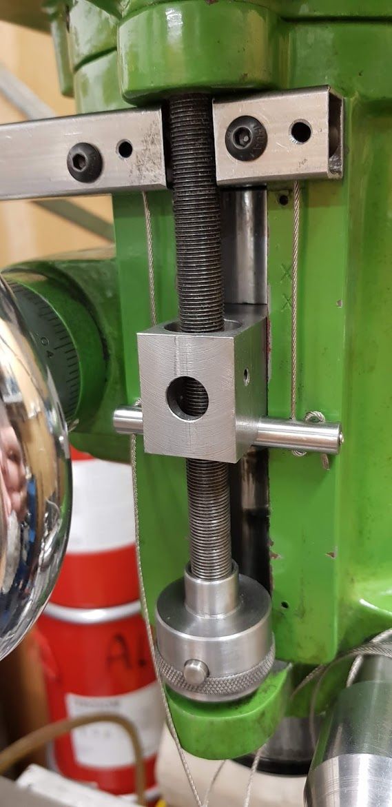
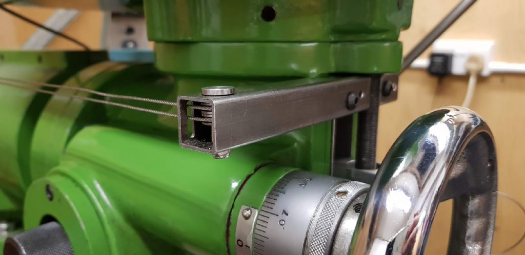
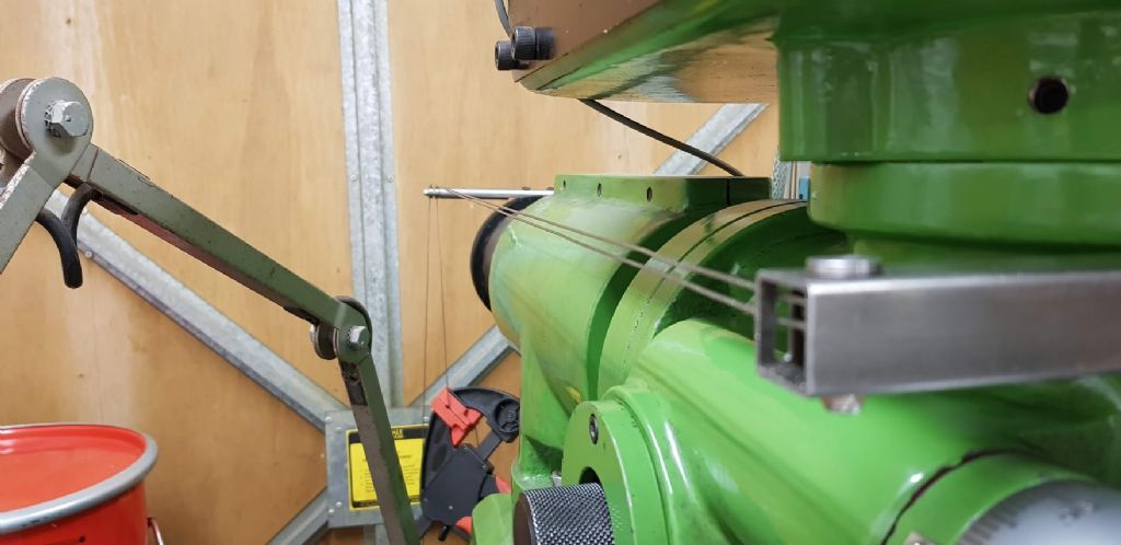
                                I've adapted the existing quill guide block to carry a bar that's pulled up on each side by two 1mm stainless steel ropes that are tensioned by weights at the back of the machine.

                                quill block.jpg

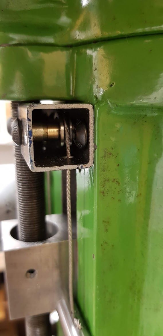
                                The routing of the cables to the back is dealt with by a series of pulleys in a length of steel box section:

                                right end.jpg

                                box exit.jpg

                                side view.jpg

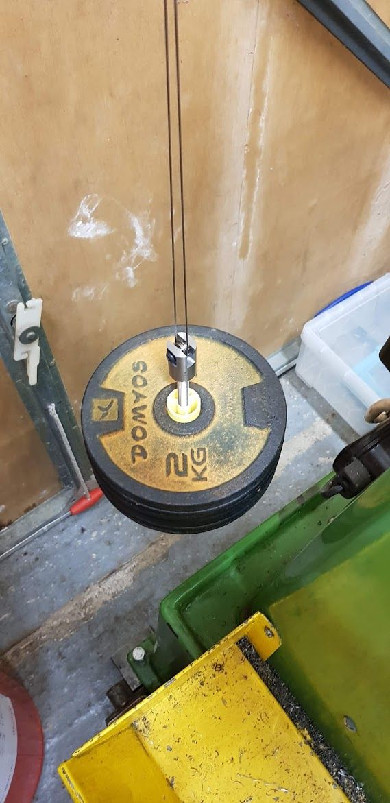
                                and finally there are ~8kgs of weights hanging on the end pulling on the cable. I printed a spacer bush to keep everything central and nicely symmetrical – much more material efficient than turning up something from the stock I had to hand:

                                weights.jpg

                                (Some of the pictures were taken before the weights were attached, hence the cables are slack)

                                So far, it's doing really well – I'm confident that the cable strength is sufficient for the application – each cable only carries around 5kgs, and the manufacturers tell me that even with de-rating, each 1mm cable is comfortably rated at 25kgs. I've used the largest hardware (M5 mostly in pairs) that I could comfortably fit in, so in theory at least nothing is close to breaking.

                                Finished a week or so ago, I think it's doing the job I might add some more weight to make the upwards force a little more positive, but the backlash and lumpiness is largely gone!

                                #514934
                                YouraT
                                Participant
                                  @yourat

                                  Oh – and I also forgot to say that I've removed the spring that was biasing the pinion upwards…

                                Viewing 15 posts - 1 through 15 (of 15 total)
                                • Please log in to reply to this topic. Registering is free and easy using the links on the menu at the top of this page.

                                Advert

                                Latest Replies

                                Home Forums Manual machine tools Topics

                                Viewing 25 topics - 1 through 25 (of 25 total)
                                Viewing 25 topics - 1 through 25 (of 25 total)

                                View full reply list.

                                Advert

                                Newsletter Sign-up