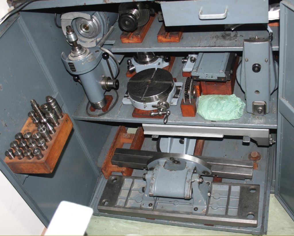
Unknown Swiss milling machine

Advert

Unknown Swiss milling machine

Home Forums Workshop Tools and Tooling Unknown Swiss milling machine

Viewing 25 posts - 51 through 75 (of 87 total)
  • Author
    Posts
  • #250637
    Michael Gilligan
    Participant
      @michaelgilligan61133

      John,

      For clarity:

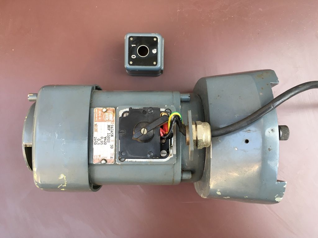
      • The Brown Boveri motor, for the Aciera head, is currently wired Star 420V, and does not appear to be readily convertible.
      • The Ecole d'Electrotechnique motor, for the pantograph, is currently wired Star 415V, but is convertible to Delta 240V.

      By using the '29Hz' trick [not the '87Hz' trick mentioned by Michael Poole], I should be able to run the BB motor on 240V regardless of its nominal 420V input, and I can reconfigure the Ed'E motor to Delta 240V.

      MichaelG.

      .

      P.S. Details of the ACS150 inverter are availble here, including the User's Manual.

      http://new.abb.com/drives/low-voltage-ac/micro/acs150

      … It seems an impressively versatile device.

      .

      P.P.S. … I purchased from Quantum Controls, whose service was exemplary.

      Edited By Michael Gilligan on 13/08/2016 17:52:54

      Advert
      #250640
      Ajohnw
      Participant
        @ajohnw51620

        It should be OK Michael as it involves more or less halving the current in the motor. Voltage is reduced so the heating effects will be as well. The fan on the motor should show the same sort of reduction in cooling effects so put together 29Hz should be as rock solid as 50. This is what they seem to be implying anyway.

        If the current wasn't halved as well that wouldn't be true. I thought that might help with heating at first -> I^2 R but forgot that the resistance is higher.

        John

        #250661
        Ajohnw
        Participant
          @ajohnw51620

          blushCan't edit the last post and I have my doubts.

          As I read it the inverter will allow the motor current to get to it's rating at 29Hz just as it would at 50Hz if there was enough voltage. 29Hz just happens to be the point where a 440 inverter would be outputting the level a 240volt one can. So effectively as far as the motor is concerned it's just like driving at 29Hz from a 440 inverter.

          This leaves the usual inverter problem. The watts lost in heat relates to I^2*R and that's still the same but the cooling fan is running at a lower speed.

          I'd guess this is why they mention home workshop. If you do it I would be inclined to keep a close watch on how hot the motor gets.

          I have a Boley lathe that uses a flanged motor. I assume this mill does too. Just a thought for if you do have problems. Getting one with the same flange fitting wasn't a problem. As the motor is a lot newer than the lathe it seems that they have retained the dimensions. The lath was fitted with a 2 speed motor. I had no chance of using that. No way to sort the snipped off wires for one. It's very similar to the Size 2 production lathe. From memory everything still fitted together even shaft size but do check that. It's a simple arrangement. The motor swings on the back of the bed to tension the belt. You might find that a bit more power is available in the same size. Lots of people have come to the conclusion that's not a bad idea when inverters are used. Some in fact have bought the lot again.

          I assume that these motors could also be obtained with 6 or 8 poles if you want to bring the revs down. I hadn't the guts to try 8 pole so went for 6. To risky money wise. I noticed that one ebayer was selling 6 pole now so maybe the idea has caught on.
          I am surprised just how much the Transwave static converters cost now so even used that is likely to be an expensive option.

          John


          Edited By Ajohnw on 13/08/2016 23:34:39

          #250764
          Ajohnw
          Participant
            @ajohnw51620

            Had another thought based around the Seimen's paper. Not sure if it will help though.

            If say the motor is to be run at 1/2 speed it would be fair to say that the cooling from the fan would 1/2 what it was at full speed.

            The heating effects are mostly down to the resistance of the winding so that power is I^2 * R. So to balance that out with the reduced speed the motor current could be set at 1/2 (It's rated current)^2. So say that was 6 amps the setting would need to be root 6^2/2= 4 1/4 amps so at full speed it will have about 2/3 of the power it did have. It will also be run at a lower voltage so could be speeded up retaining the same current level.

            frownAt 1 amp it comes out at 0.7.

            I don't think that much heat is lost in eddy currents but as motors are often designed to be run in 40C ambients ( check that ) there is some scope anyway.

            I think I might give this a whirl on my Boxford. I fitted a 1hp motor and reducing that by say 30% wouldn't hurt really and I would still get the same current for some range of higher speed running. Only thing is Mitsubishi might not let me set the current that low. I think they do this because of the overload capacity in the various sizes – the oh dear overload level.

            John

            #250922
            Michael Gilligan
            Participant
              @michaelgilligan61133

              I had a look at the motors and wiring today.

              The inverter manual correctly specifies screened cable for the motor [see page 30], and advises against externally switching the 3-phase output.

              This therefore seemed an appropriate time to remove the switches and leads.

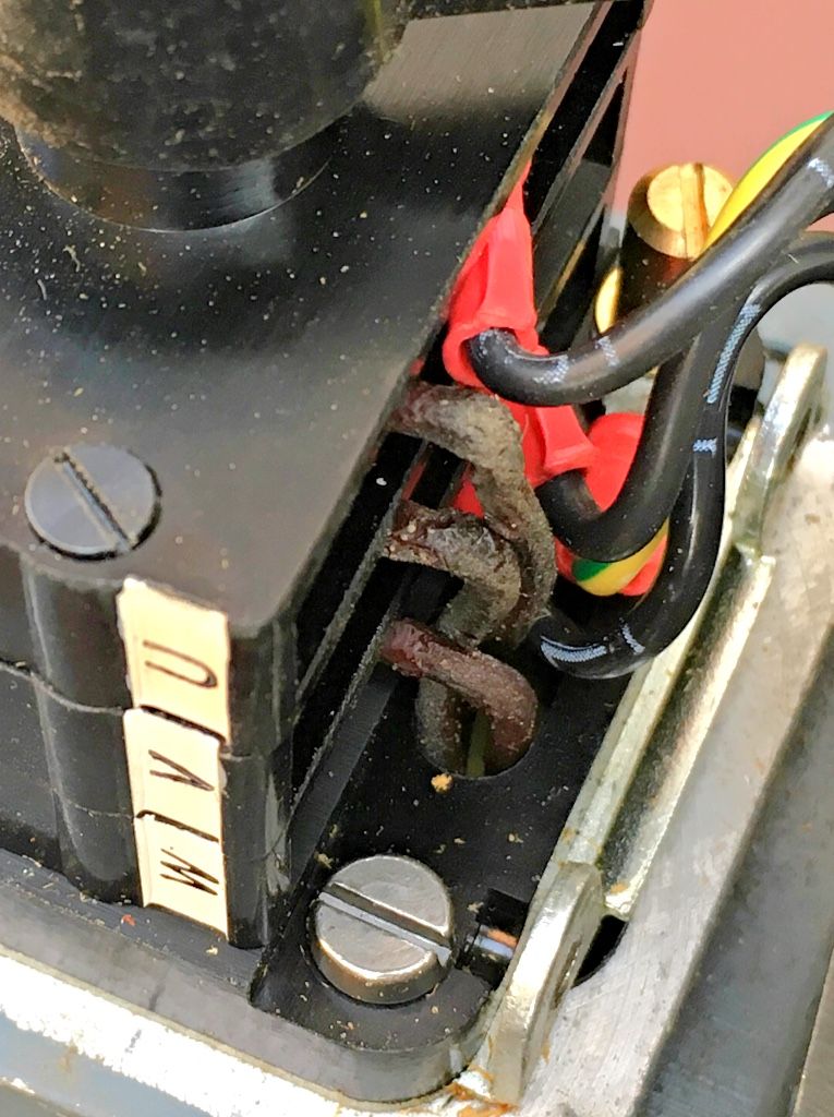
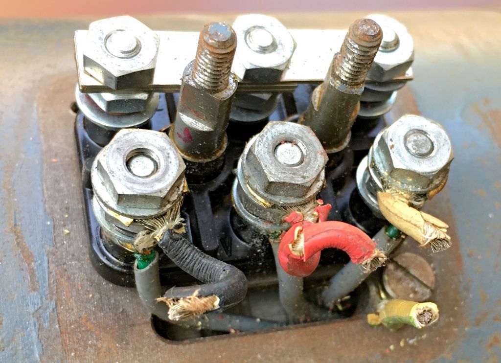
              • The flex to the Ed'E pantograph motor was rubber, and badly degraded … [snipped off for this photo], but the internal motor wiring has much better insulation, and looks fine.

              image.jpeg

              .

              .

              • Contrary-wise; the flex on the BB motor, for the Aciera head was PVC insulated, and in good condition, but the insulation on the motor wires felt rather tacky.

              image.jpeg

              image.jpeg

              image.jpeg

              .

              Next step is to remove the switch from the motor and check the condition of those wires.

              .

              MichaelG.

              #250931
              Ajohnw
              Participant
                @ajohnw51620

                It might be some sort of treated cotton wire covering Michael. I have come across that in a number of older things that involve winding bare wire. I can also be slipped over normal cable. I wouldn't worry to much about it feeling tacky but I have no idea what they put on it other than it's probably some sort of varnish that tends to stop like that.

                surpriseI'm glad this thread came up. I've been trying to figure out how to re arrange my Pulta's motor and belts and pulleys. I new feel I can get a dead safe 3:1 speed variation out of a suitable motor. Maybe even 4:1. That will help a lot.

                Just add when you get there I usually put an ammeter in the earth return lead off the motor to check that there aren't any internal shorts. Some current is very likely to flow and suitable numbers can be found on the web. There are 2. One for "fixed" wiring and another where I assume there is a plug on the end.

                You'll find armoured cable to connect the motor to the inverter on the web or try asking a local electricians supplier. I did and they gave me 12ft of it.

                John

                Edited By Ajohnw on 16/08/2016 00:02:48

                #250932
                John Stevenson 1
                Participant
                  @johnstevenson1
                  Posted by Ajohnw on 13/08/2016 12:15:52:

                  I'm getting a bit fed up of the inverter noise even at high switching frequencies and random switching. It also isn't good for the motors – circulating currents through the bearings. Not that we generally use gear for the length of time that probably needs to cause serious problems.

                  John

                  Read the book then and adjust the carrier frequency.

                  #250940
                  Michael Gilligan
                  Participant
                    @michaelgilligan61133

                    A brief [and hopefully useful] note on VFD Motor Cables:

                    Here is an example of a cable that is properly engineered for the job:

                    http://www.elandcables.com/handlers/downloadpdf.ashx?url=/media/38848/variable-frequency-drive-medium-voltage_2.pdf

                    I was rather concerned that this construction might be too stiff; given that both motors on my machine need 'flex' rather than 'cable'.

                    So I asked 'Quantum Controls' for advice; and their Service Manager promptly replied with this very helpful guidance: "It is best practice to use a 3 core symmetrical shielded cable, however if the cable is less than 10mm a 4 core will suffice. This means you can use a 4 core 1.5mm SY cable on the motor for a drive this small, this will give you a 3 core and earth. You will also need to ground the cable screen at one end."

                    Now this is good news, because SY is cheap, reasonably flexible, and readily avalable: **LINK**

                    http://www.ebay.co.uk/itm/391433134625?_trksid=p2055119.m1438.l2649&ssPageName=STRK%3AMEBIDX%3AIT

                    MichaelG.

                    #250941
                    David Jupp
                    Participant
                      @davidjupp51506

                      SY cable is less good at preventing RFI/EMC problems in inverter powered systems than CY cable. CY isn't particularly expensive – I recently purchase 3core + Earth CY to connect motors to VFDs on some pump systems. Finding the EMC glands was trickier.

                      The first cable linked to by Michael is 'medium voltage' – so above 1kV, not really what you'd consider for the size of motor here.


                      Edited By David Jupp on 16/08/2016 08:04:50

                      Edited By David Jupp on 16/08/2016 08:06:07

                      #250942
                      Michael Gilligan
                      Participant
                        @michaelgilligan61133
                        Posted by David Jupp on 16/08/2016 07:53:39:

                        SY cable is less good at preventing RFI/EMC problems in inverter powered systems than CY cable. CY isn't particularly expensive – I recently purchase 3core + Earth CY to connect motors to VFDs on some pump systems.

                        .

                        David,

                        Pardon my innocence/ignorance, but is CY both flexible and strong ?

                        MichaelG.

                        .

                        Edit: It would appear that CY is less mechanically suited to my requiremets.

                        https://en.m.wikipedia.org/wiki/SY_control_cable#CY_and_YY_Control_Cables

                        Edited By Michael Gilligan on 16/08/2016 08:24:06

                        #250943
                        Michael Gilligan
                        Participant
                          @michaelgilligan61133
                          Posted by JasonB on 16/08/2016 08:06:59:

                          Posted by Michael Gilligan on 16/08/2016 07:29:12:


                          …………….less than 10mm a 4 core will suffice. This means you can use a 4 core 1.5mm SY cable

                          Michael could you just confirm that the first measurement is diameter and the second area as if they were both area there could be some hot wirescrook

                          .

                          I did wonder that, Jason, but decided not to trouble them further because my own question was already answered.

                          It is quite plausible that both refer to conductor areas … Have a look at Quantum Controls website and you will see that they deal in some quite large VFD systems, and some very big motorssurprise

                          MichaelG.

                          .

                          Edit: added link to

                          http://www.quantum-controls.co.uk/products/abb-ie-3-motors.html?dir=desc&order=outputkw

                          Edited By Michael Gilligan on 16/08/2016 08:38:08

                          #250946
                          Michael Gilligan
                          Participant
                            @michaelgilligan61133

                            Too late to edit my last post … Here is the big ABB controller:

                            **LINK**

                            http://www.quantum-controls.co.uk/products/abb-variable-speed-drives/acs800-01-0120-5.html

                            MichaelG.

                            #250952
                            Ajohnw
                            Participant
                              @ajohnw51620
                              Posted by Michael Gilligan on 16/08/2016 07:29:12:

                              Now this is good news, because SY is cheap, reasonably flexible, and readily avalable: **LINK**

                              http://www.ebay.co.uk/itm/391433134625?_trksid=p2055119.m1438.l2649&ssPageName=STRK%3AMEBIDX%3AIT

                              MichaelG.

                              That is exactly the type of cable I suggested and what many use.

                              Your inverter manual should spec the cable size.. The 1.5mm is the cable area and you may find that you have to use a larger size than the manual suggests.

                              The feed to the inverter is usually filtered internally but nor always.

                              JS – Don't you think that I have already done that ? Probably not it seems. They can be made as quiet as an ordinary motor set up but it's an expensive option. Not doubt I have the nosiest inverter on the market.

                              John

                              #250954
                              David Jupp
                              Participant
                                @davidjupp51506

                                Michael – CY has copper (usually tinned) braiding in place of the steel braiding of SY. No it isn't as 'strong' but it does conduct RF frequencies to ground more effectively. For avoiding RFI/EMC issues it is a better bet. You'll have to decide what balance is necessary in your application between mechanical robustness and EMC performance.

                                #250959
                                Michael Gilligan
                                Participant
                                  @michaelgilligan61133
                                  Posted by David Jupp on 16/08/2016 09:43:58:

                                  Michael – CY has copper (usually tinned) braiding in place of the steel braiding of SY. No it isn't as 'strong' but it does conduct RF frequencies to ground more effectively. For avoiding RFI/EMC issues it is a better bet. You'll have to decide what balance is necessary in your application between mechanical robustness and EMC performance.

                                  .

                                  Thanks, David

                                  I think I'm happy to go on the advice of the ABB Drives & Motors 'Supplier of the Year'

                                  **LINK**

                                  http://www.quantum-controls.co.uk/about-us/about-us.html

                                  Incidentally; I only posted the 'Eland Cables' link because it includes a good diagram of the preferred 'symmetrical' construction.

                                  MichaelG.

                                  #251176
                                  Ajohnw
                                  Participant
                                    @ajohnw51620

                                    There is some info about from Mitsubishi on emissions Michael. Length is probably more important than anything else. It's best to keep the motor power lead short and no longer than needed. They give info on lengths of 20m and up in some of their data sheets. The carrier frequency can also have an effect.

                                    It's possible to connect to the shielding which ever type it is via P clips. Just metal bent into the shape of a P with 2 thickness's on the upright part with a hole through them for fixing. How they can be used depends on what is being connected. Your inverter may have a plate for this used to locate the cables. I did look quickly at your manual but the clips are likely to be easier than unpicking and twisting and then fixing them in an eyelet some how.

                                    By using the armoured cable you also have an earth lead. That will also help.

                                    Not sure if I saw a note about keeping the control leads at least 10cm from the power leads.

                                    Rather long power leads to the inverter can also cause problems. The mains filters for solving that aspect are pretty cheap if needed but can cause problems with rcd's.

                                    John

                                    Edited By Ajohnw on 17/08/2016 19:50:42

                                    #251221
                                    Michael Gilligan
                                    Participant
                                      @michaelgilligan61133

                                      Thanks, John,

                                      I will have a look for the Mitsubishi information, out of interest.

                                      I should however mention that both motors for this machine will need to be on flex as opposed to cable.

                                      • The Aciera head is interchangeable with the pantograph mechanism and might best be considered as a 'portable tool'.
                                      • The motor for the pantograph is in the base of the machine, but is on a swinging-arm mounting for belt tensioning; so it too needs to be powered via flex.

                                      That's why the supplier advised the use of SY flex.

                                      MichaelG.

                                      #251223
                                      Mark C
                                      Participant
                                        @markc

                                        Michael,

                                        I think you might find this publication by Beldon interesting (I have you down as researching carefully before jumping! ) **LINK**

                                        Also of interest is the small wiring diagram at the top of page 2 showing the earth screen connected both ends – the way I understood it was meant to be done rather than the conventional single ended arrangement for screens, this is the way all my personal and work installations are implemented. I understand that this is to prevent emissions rather than stop incoming interference….

                                        Mark

                                        #251226
                                        Michael Gilligan
                                        Participant
                                          @michaelgilligan61133

                                          Thanks, Mark

                                          I will read that one tomorrow.

                                          … Bedtime now.

                                          MichaelG.

                                          #251283
                                          Ajohnw
                                          Participant
                                            @ajohnw51620

                                            I don't think that the "regs" have really caught up with VFD's yet. Anyway.

                                            As far as I am concerned SY cable is armoured cable. "My bad", it's suitable for moderate mechanical stress the other type is usually used outdoors. It's not that flexible really. The ebay listing mentions the flex bending rad 20xdia which comes out at 200mm in your case. It's stiff enough to need each end of the cable anchored rather than just anchor with the wires. P clips may work out at the inverter end and metal ones can be used to earth the outer braid to form a shield. This can also be done with the copper cable. There may be enough room in the motor connection box to use them their as well or even on the outer surface of the box. The cable should be grounded at both ends some how or the other. There may be some way of attaching P clips to the inverter but the other way is to mount it on a board of some sort.

                                            The SY cables also have an earth lead. That in itself will provide some shielding.

                                            I'm not sure what to say about the cable rating. Mitsubishi suggest 2mm from 0.1 to 2,2kw. Your 1.5mm on the face of it is rated at 18 amps derated by 25% as it's multicore and yet more if the ambient is above 30C. So say 9 amps. That sounds like it's way too much but neglects skin effects which is important because high frequency is being sent down the cable. I haven't managed to find any info on that so far but do know from work on switch mode supplies that it's relevant. Mitsu are probably assuming that the full 15khz is going to be used and maybe a long length as well. I did find this recently while looking again, I gave up when I installed mine and had to use > 2mm anyway. 2.5mm is not much bigger than 1.5mm. 10.7mm as against 9.2mm.

                                            **LINK**

                                            Personally I feel your 1.5mm should be fine but on the face of it you might think you could use smaller to get more flex but normal current ratings don't account for high frequencies.

                                            They also suggest 2mm for the mains feed to the inverter except for 2,2kw which needs to be larger, earth lead too. The peak current draw can be pretty high on these things but this lead is the one that actually goes to ground.

                                            There is plenty of warnings about on using high switching frequencies on normal motors. There are all sorts of changes in inverter rated ones not just the addition of a fixed speed cooling fan. This tends to be ignored completely 'cause the things are so insanely expensive but it doesn't make sense to set the switching frequency any higher than needed. I've seen claims that this can increase heating effects by 10% but the main problem seems to be higher than normal voltage spikes in the motor and current flowing across the bearings.

                                            John

                                            #251296
                                            Michael Gilligan
                                            Participant
                                              @michaelgilligan61133

                                              John,

                                              I don't wish to be rude, or ungrateful, but:

                                              I explained about my motors and their mounting to 'Quantum Controls' and asked for specific advice; which they have kindly given.

                                              The Aciera head is like the one pictured here, dismounted, in the stand of an F3

                                              https://goo.gl/images/jH21yF

                                              It is, and must remain "portable" and therefore I have to arrange my wiring accordingly.

                                              MichaelG.

                                              .

                                              Edit: Image froms lathe.co.uk [as credited above]

                                              image.jpeg

                                              Edited By Michael Gilligan on 18/08/2016 11:29:20

                                              #251311
                                              Ajohnw
                                              Participant
                                                @ajohnw51620

                                                laughI can't say that I mentioned anything that prevents you from wiring as you want to. Just passing on some info from my own experience and recommendations from a rather major inverter manufacturer. Given the set up you have I know what I would do and yes it wouldn't entirely agree with inverter manufacturers general comments on wiring but only in terms of plugs.

                                                John

                                                #251407
                                                Michael Gilligan
                                                Participant
                                                  @michaelgilligan61133
                                                  Posted by Michael Gilligan on 18/08/2016 00:10:52:

                                                  Thanks, Mark

                                                  I will read that one tomorrow.

                                                  .

                                                  Mark,

                                                  Thanks again … That's an excellent document [probably the best eight pages I have read on the subject so far]

                                                  Just a few minor observations which may be useful to others:

                                                  • On page 2 "effect" should read "affect"
                                                  • The statement on page 4: "Ground sizes allowed by the National Electrical Code (NEC) vary by conductor size, but, except in smaller cables, they are typically required to be significantly smaller than the circuit conductors." [although clarified later] is misleading. … The ground sizes are not required to be significantly smaller; they are permitted to be significantly smaller !!
                                                  • On page 5, there is a very important observation which gives 'scale' to the discussion: "Opinions vary among VFD manufacturers, but Belden's research suggests that the benefits of symmetric design to prevent internally generated ground currents begins to be a design factor for motors above 50hp with very long runs, but is typically more significant in motors greater than 100hp."

                                                  MichaelG.

                                                  #251410
                                                  Mark C
                                                  Participant
                                                    @markc

                                                    Michael,

                                                    Yes, I prefer that sort of information over "hear say" and assumption.

                                                    Over very short runs (less than 1200mm) I have to confess to using CG (common or garden) 4 core flex suitably sized on my lathes but I also use a motor side choke on all my machines to improve the life expectancy of my old fashioned motors.

                                                    Mark

                                                    PS. I have recently installed a crane in my garage and was thinking of taking some pictures and posting them for you regarding your interchangeable heads on this machine. I have been very busy but will try and get it done if you still have the lifting problem.

                                                    #251414
                                                    Michael Gilligan
                                                    Participant
                                                      @michaelgilligan61133

                                                      For info.

                                                      I have an early model [2.4i] of the Wi-Spy, from MetaGeek, which should serve as a basic interference detector.

                                                      **LINK**

                                                      http://www.metageek.com/products/wi-spy/?utm_expid=190328-158.sOrYCB04S9ag3e0x8LJbGw.0&utm_referrer=http%3A%2F%2Fwww.metageek.com%2Ftraining%2F

                                                      … Should be interesting.

                                                      MichaelG.

                                                    Viewing 25 posts - 51 through 75 (of 87 total)
                                                    • Please log in to reply to this topic. Registering is free and easy using the links on the menu at the top of this page.

                                                    Advert

                                                    Latest Replies

                                                    Viewing 25 topics - 1 through 25 (of 25 total)
                                                    Viewing 25 topics - 1 through 25 (of 25 total)

                                                    View full reply list.

                                                    Advert

                                                    Newsletter Sign-up