Uniform Depth Bevel Gear,,,”MODULAR” not “DP”

Advert

Uniform Depth Bevel Gear,,,”MODULAR” not “DP”

Home Forums Hints And Tips for model engineers Uniform Depth Bevel Gear,,,”MODULAR” not “DP”

Viewing 20 posts - 1 through 20 (of 20 total)
  • Author
    Posts
  • #697123
    conrod
    Participant
      @conrod

      I started out in feet and inches, then was forced to go to that funny stuff, but still think in “thous”.

      However building a 4 truck Shay in 5 inch, and need to cut gears. Mod gear cutters are easy to get and steel is all in mm so have to use that system.


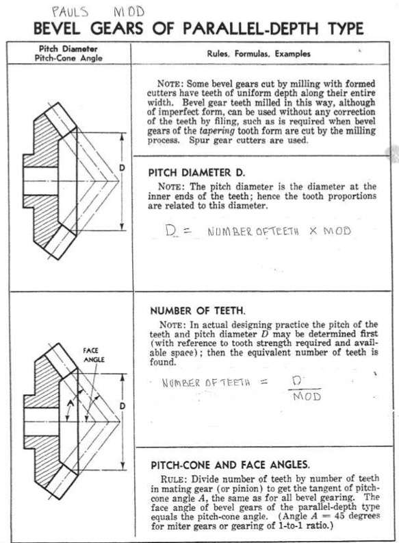
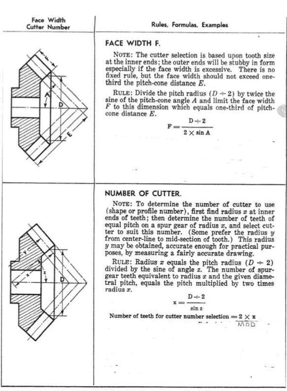
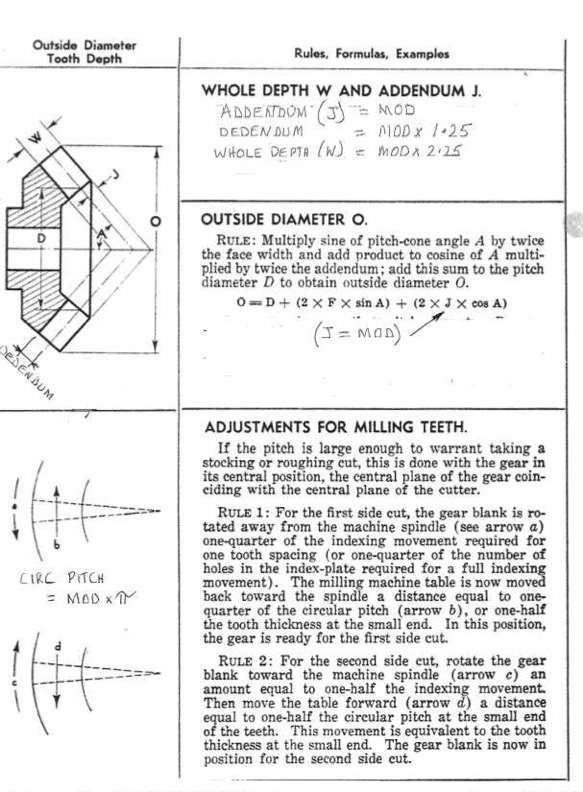
      Cutting 49 and 20 tooth gears as per ogiginal 1 to 1 scale loco, to get them onto 100mm dia wheels need to use 1.25 mod cutters, could not find any info on “mod parrallel depth info” but plenty on DP gearing, so plagerised DP info sheet to MOD, thought Id post it here in case anyone else was looking.

      I forgot where I downloaded it from so if anyone can tell me Ill credit the original producer.modamodbmodc

      Advert
      #697136
      Diogenes
      Participant
        @diogenes

        It’s from ‘Gear Design Simplified’ by Franklin Jones & Henry Ryffel, published by Industrial Press of New York 1961.

        Still available – ISBN 978-0-8311-1159-5

        Incidentally they offer a smaller multiplier for calculating the dedendum (1.157) rather than 1.25 but I’m sure you knew this and deliberately opted for modification given the pinion size.


        #697367
        DC31k
        Participant
          @dc31k
          On Diogenes Said:

          …smaller multiplier for calculating the dedendum (1.157) rather than 1.25

          That is the convention between DP and MOD gears. DP generally used 1.157, MOD used 1.25.

          To the OP:

          I guess you have seen this thread:

          https://www.modelenginemaker.com/index.php/topic,9935.0.html

          Another good source for cutting the gears is this (page 113)

          https://archive.org/details/handbookformachi00halsrich/handbookformachi00halsrich/

          #698965
          conrod
          Participant
            @conrod

            Hi DC31k

            I got the 1.25 from this site.  “GEAR SOLUTIONS,,,Pitch perfect gear design”,,,,they said “”For a DP gear, the addendum is equal to 1/DP, the dedendum is equal to the whole depth minus the addendum, and the whole depth is equal to 2.157/DP. When dealing with module, the addendum is equal to the module, the dedendum is equal to 1.25 times the module, and the whole depth is equal to 2.25 times the module.””


            #698979
            DC31k
            Participant
              @dc31k
              On conrod Said:

              I got the 1.25 from this site.  “GEAR SOLUTIONS, Pitch perfect gear design”…

              What you have is correct, conventional and in particular un-remarkable.

              My comment above was addressed to Diogenes, who appeared to think you were doing something out of the ordinary.

              More about parallel depth bevels on page 161 of the pdf (144 of the printed book) here:

              https://archive.org/details/americanmachnis00logugoog

              and here:

              https://archive.org/details/sim_american-machinist_1891-09-10_14_37 (page 6 of both pdf and printed work)

              #699079
              Neil A
              Participant
                @neila

                The question of the depth of gear teeth has come up before. The clearance value has increased over the years.

                For spur gears the value of 0.157 is now generally associated with gears having a 14 1/2 degree pressure angle. The value for gears with a 20 degree pressure angle was increased to 0.25 in BS 436 : 1932. This was to accommodate a larger root radius. For gears that are finished by grinding this is usually increased to 0.4. This applies to DP, Circular Pitch and Module designated gears.

                On bevel gears Gleeson Works gave a value of 0.188 for use with their standard cutters. BS 545 : 1945 increased this value to 0.25 the same as spur gears. The book ‘Gear Engineering by H.E.Merritt’ suggests a better value is 0.2, as the cutter point width and fillet radius can become rather small toward the inside of the gear where the tooth forms converge.

                These things are rarely simple and straight forward. It really all depends on the method of manufacture. At the end of the day it is only clearance we are talking about.

                Neil

                #699113
                DC31k
                Participant
                  @dc31k
                  On Neil A Said:

                  …It really all depends on the method of manufacture.

                  Do any of your references have anything to say on additively-manufactured (for example, 3D printed) gears?

                  On those, the root geometry is not dictated by the swept path of a cutter removing material so can be optimised for strength.

                  See this paper from 2009 that touches on the subject:

                  Gear Tooth Fillet Profile Optimization

                  #699131
                  John Hinkley
                  Participant
                    @johnhinkley26699

                    Having merely skipped through this thread, I have had a quick play with bevel gears in Fusion 360.  Using the GF Gear Generator add-on, I produced a couple of bevel gears in metric/MOD form.  Taking measurements from the resultant models, they appear to be parallel cut gears.  Could equally easily be produced in Imperial/DP.  I guess you could also get it to print out 2D views although I have no experience with Fusion in doing this.

                    I realise that this has no bearing on the OP’s question, but is another addition to our armoury of tools.

                    John


                    #699172
                    Neil A
                    Participant
                      @neila

                      In answer to DC31k, I’m afraid that all of my references are for the manufacture of gears by cutting the tooth space. The size of the fillet radius is defined in the BS as being between 0.25 and 0.39 for a unit metric module basic rack. My understanding is that this is the radius as applied to the cutting hob, the curve generated for the fillet is no longer a true radius but a trochoid. I think that plain gear milling cutters would probably have a true radius for the fillet, but I’m not sure which end of the cutting range the manufacturer might choose.

                      I fear that we have drifted off the OP’s subject a bit, I think that it is now time to resume the original thread on uniform depth bevel gears.

                      Neil

                      #699187
                      conrod
                      Participant
                        @conrod

                        Great to see some interest in my post, thanks to all for comments and the book references are great, goig to do some reading tonight.

                        Hope to start cutting this weekend, will post photos of progress and final results.

                        #702421
                        conrod
                        Participant
                          @conrod

                          Have finally turned down a blank and ready to cut gears,,,BUT,,,,second thoughts on Addendum/Dedendum/Whole Depth.

                          WHOLE DEPTH equals Addendum plus Dedendum

                          Happy with Addendum equals MOD,,,and happy with Whole Depth equals 2.25 times MOD

                          but not happy with Ded=1.25 mod. Thinking back to High School maths,,,,,MODx2.25 does not equal Mod+MODx1.25

                          Should I have said in first post:

                          Whole Depth equals MOD times 2.25,,,,ADDENDUM equals MOD,,,,DEDENDUM equals WHOLE DEPTH minus MOD????


                          #702467
                          conrod
                          Participant
                            @conrod

                            Or did I get my maths wrong ans Dedendum equals Mod times 1.25????


                            #702481
                            DC31k
                            Participant
                              @dc31k
                              On conrod Said:

                              Thinking back to High School maths, MODx2.25 does not equal Mod+MODx1.25


                              The dish was well-cooked on the initial pass through the brain. Further marination in the grey soup has not improved the flavour.

                              1 orange added to 1.25 oranges gives me 2.25 oranges.

                              Pick a number for MOD (e.g. 10). 10 plus 12.5 equals 22.5

                              #702483
                              Pete Rimmer
                              Participant
                                @peterimmer30576
                                On conrod Said:

                                Thinking back to High School maths,,,,,MODx2.25 does not equal Mod+MODx1.25

                                According to the rule of BODMAS it does, because the multiplication is always done first.

                                MOD + (MOD x 1.25)


                                #702487
                                Michael Gilligan
                                Participant
                                  @michaelgilligan61133

                                  Succinct, Pete

                                  MichaelG.

                                  #702512
                                  conrod
                                  Participant
                                    @conrod

                                    Thanks fellas,so I got it right first time

                                    been a long time since high school,,,54 years to be exact,,,or is that 55 years??,,

                                    You were correct DC31k,,,I should not overthink.

                                    #702605
                                    Neil Wyatt
                                    Moderator
                                      @neilwyatt

                                      Has anyone tried designing gears using Filengrene yet?


                                      Link to video that accompanies Jacques Maurel’s article:

                                      Neil

                                      #702833
                                      conrod
                                      Participant
                                        @conrod

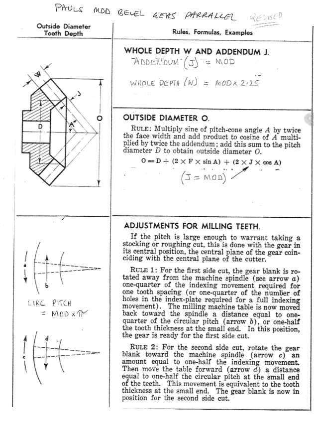
                                        Sorry DC3 I have been thinking again,,,to design the gear I dont need the Dedendum. Just Addendum and Whole Depth. Using the Dedendum is just “chain dimensioning” and my High School Tech Drawing teacher Mr Smith would be horrified! he said “there is a special place in Hell for people who chain dimension, its across the hall from where they put people who confuse Helix’s and Spirals”.

                                        So here is the REVISED PAULS WHOLE DEPTH AND ADDENDUMmodanoded

                                        #703780
                                        conrod
                                        Participant
                                          @conrod

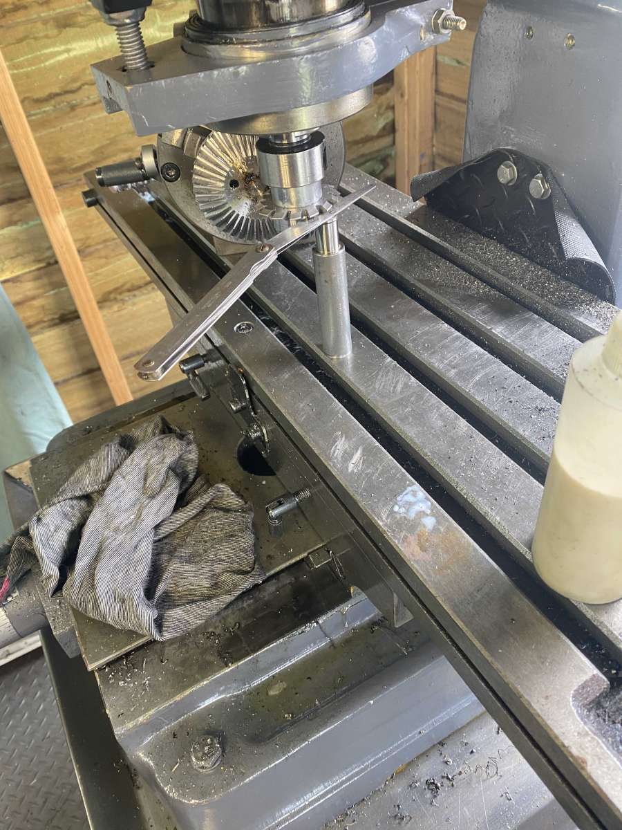
                                          Cut a gear today for third time, had trouble with the lowering and raising of cutter from centre line just couldn’t get it right.

                                          After sleeping on it I hit on the idea of making a “spacer” from round stock. Centre height is 100mm (sorry have to use that stuff, all Aussie is mm unfortunately) The thickness of cutter is 4.4mm and the required offset is 1.17mm up and down from centre.

                                          So at the lowest position the spacer is 96.63mm long (underside of cutter is 100 centre minus 2.2mm (half the cutter) minus 1.17 offset)

                                          At centre height I use the spacer plus 1.17 feelers

                                          At higest position it the spacer plus2.34 feelers,,,,strangely enough it worked,gear


                                          #704004
                                          DC31k
                                          Participant
                                            @dc31k
                                            On conrod Said:

                                            Cut a gear today… …it worked.

                                            Well done. I like the spacer idea.

                                            It struck me that there might be opportunity to use the quill depth stop in a similar way. Set the stop for the lowest position and then insert spacers between the stop nut and whatever it touches for the other two positions.

                                            Being mean, it would save me nearly 100mm of material. It also means you do not have to move the table around to find a place for the spacer to rest on.

                                          Viewing 20 posts - 1 through 20 (of 20 total)
                                          • Please log in to reply to this topic. Registering is free and easy using the links on the menu at the top of this page.

                                          Advert

                                          Latest Replies

                                          Viewing 25 topics - 1 through 25 (of 25 total)
                                          Viewing 25 topics - 1 through 25 (of 25 total)

                                          View full reply list.

                                          Advert