So the question is, is there a way to adjust the quill?
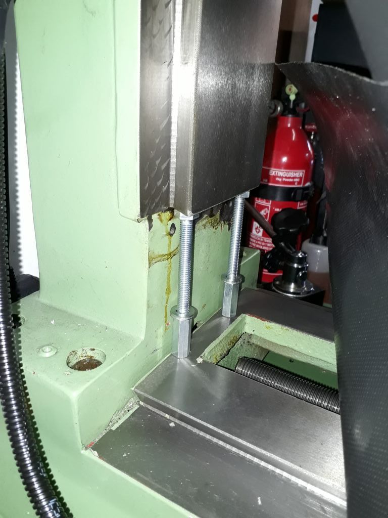
To be able to swivel the head, you have two parts – the base casting that moves on the dovetailed column & the quill carrier / spindle motor mount casting. One of these will probably have a spigot to locate in a hole in the other to act as the swivel bearing & a couple of tee bolts to hold the two parts together. From your description, it would seem that one or other (or both) of the faces on these parts that bolt together is out of alignment. You will have to dig deeper to find out where the error lies in order to determine how to improve the situation
I would proceed like this :
Firstly, completely separate the two castings, thoroughly clean both faces of paint, swarf etc. and deburr. Might be worthwhile to blue up one part & offer it up to the other to see how well the two faces fit together. Re-assemble and recheck the head / quill / spindle alignments to see if the test results have changed. Bear in mind that to separate the two parts to work on them you may need to disconnect wiring & that the quill carrier casting is probably heavy. If your alignments were OK before you set the head at an angle, it might be just contamination of the joint that has caused the current issue – you might get lucky !
If the results are still not acceptable, split the castings again and carry out a check on the base casting joint face to make sure that it is parallel to the dovetail ways / column. Put a dial gauge magnetic base on the table, adjust to touch the joint face at , say, the 3 o'clock position. Zero the dial gauge after locking the Y axis, then manipulate the X and Z axes to move the dial gauge around the joint face to the 6, 9 & 12 o'clock positions. If the 12 & 6 o'clock readings are different from the readings off your square, it would suggest that the joint face is not parallel to the dovetails. To keep track of the numbers, use a marker pen to write directly on to the casting face – saves messing about with scraps of paper.
If you have a surface plate, place the quill carrier casting joint face down on the plate – if there is a spigot to centre the casting preventing the joint face sitting on the plate, use parallels. Fully extend the quill & lock it. With the dial gauge mounted on a surface gauge (or use a magnetic base on wide parallel) slide the dial gauge back & forth across the top of the quill nearest the casting & set zero. Repeat the check at the outermost end of the quill – the quill should be parallel to the joint face. If you don't have a surface plate, there may be room to do this on the table top, which should be flat.
It would probably be worth while to check that the outside of the quill is parallel & check the fit of the quill in the casting bore with the return spring & pinion removed. Bit difficult to sort a loose quill, though, as you need a "putting on" tool ! At the last employment we sent them (and tailstock barrels) out to a specialist firm who honed the bores, hard chrome plated the quill & ground back to get the correct fit. As you might expect, not a cheap option.
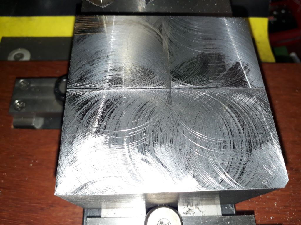
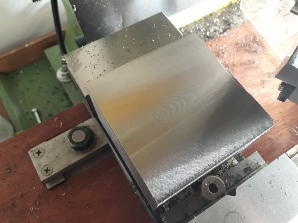
I would probably scrape out any errors in the joint faces, as the amounts to be removed are probably not that great, though it may be possible to machine them – depends on your equipment etc. It is worthwhile double checking your readings before putting scraper to metal – it is easy to knock the dial gauge, so I always go back to the initial zero setting position to check it is still zero. If you don't get reliably repeatable results, re-assess your methods.
HTH
Nigel B
ChrisB.


