Stepper Motor Identification

Advert

Stepper Motor Identification

Home Forums General Questions Stepper Motor Identification

Viewing 25 posts - 1 through 25 (of 50 total)
  • Author
    Posts
  • #376570
    Alan Charleston
    Participant
      @alancharleston78882

      Hi,

      A couple of years ago I bought a second hand stepper motor with the intention of using it to position my vertex dividing head and speed up cutting gears. I have a StepDuino to control it. It is a KH56 series motor with the first part of the serial number being KH56KM2. I have found a spec. sheet on line for this model but the last three numbers quoted are -911, -912 and -913 whereas the last part of the serial number on the motor is U037. I presume the U stands for Uni-Polar (there are 6 wires coming out) but the 037 doesn't correspond to what's on the spec sheet. The difference between the last three digits seems to be the motor voltage which changes from 2.3V (3.0A) to 3.6V (2.0A) and 6.71V(1.0A) with the power being about 7 watts for the three options.

      Can anyone help me determine what voltage I should be applying to the motor? I'm a complete novice with these so don't assume I can see the obvious.

      Regards,

      Alan

      Advert
      #26248
      Alan Charleston
      Participant
        @alancharleston78882
        #376573
        John Haine
        Participant
          @johnhaine32865

          The first thing is to use a multimeter to check the windings. I would guess that it has two centre tapped windings, which can be used with unipolar or bipolar drives. You want to use the latter nowadays. For this you need to find the centre taps, and then not connect them but use the ends of the windings as a1, a2, b1 and b2 as in the stepduino guide.

          The motor voltage is a red herring, what matters is the current. If you use a modern driver it will typically need around 24 volts upwards and will allow you to set the drive current to what your motor needs. The Stepduino has two such drivers installed. I assume it has a facility to set the maximum current. If you start at 1 amp you can't go wrong. If you don't get enough torque and the motor isn't getting too hot then turn it up. Forget the voltage, that will be taken care of by the driver.

          Can you post a photo of the motor?

          #376576
          Alan Charleston
          Participant
            @alancharleston78882

            Hi John,

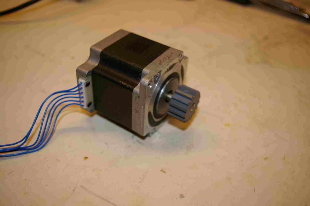
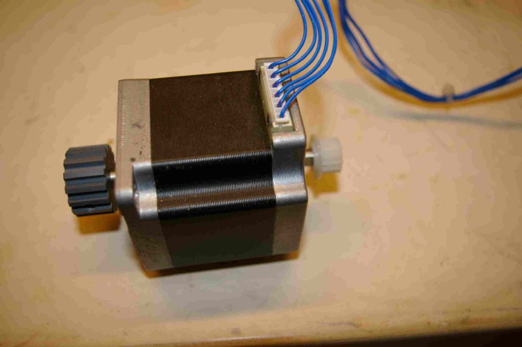
            Thanks for your reply. I haven't got as far as learning how to use the StepDuino yet as I thought I would need to know the motor characteristics first.I didn't realise you set the current instead of the voltage. I have attached a couple of pictures of the motor. The body is about 55mm across. I will go through the training exercises for the Arduino (again – I wish the information would stick) and then try using the stepduino.

            Regards,

            Alan

            stepper1.jpg

            stepper2.jpg

            #376578
            not done it yet
            Participant
              @notdoneityet

              You will need to convert your metric to imperial as the nema system works on inches. Searching for nema system motor sizes should find you more info.

              #376581
              John Haine
              Participant
                @johnhaine32865

                That's a NEMA 23 motor – 2.3 inches.

                Looking at the Stepduino schematic and the driver IC datasheet the current is set by two sensing resistors on the board and a potentiometer which allows adjustment. It doesn't say anything about what that should be adjusted to, but from the component values and the driver datasheet the maximum current is about 2.5 amps. So if you could find VR3 on the PCB and adjust it to about half-way the current would be ~1.25A which would be about right.

                #376730
                Alan Charleston
                Participant
                  @alancharleston78882

                  Thanks John. I've measured the resistance across the coils and figured out the configuration which happily coincides with the data sheet. Now for the bit I'm not looking forward to – relearning how to use the arduino. I wish people wouldn't keep on about how easy it is to use – it's not.

                  Regards,

                  Alan

                  #376762
                  John Haine
                  Participant
                    @johnhaine32865

                    Alan, there was an article on a divider controller using Arduino in MEW a while ago. I believe the code is downloadable somewhere. Though written for the standard platform it would probably be easily adaptable.

                    #377364
                    Alan Charleston
                    Participant
                      @alancharleston78882

                      Hi John,

                      You seem to know a bit about the Stepduino so I'd like to pick your brains if I could.

                      I've managed to get the Arduino IDE talking to the Stepduino.

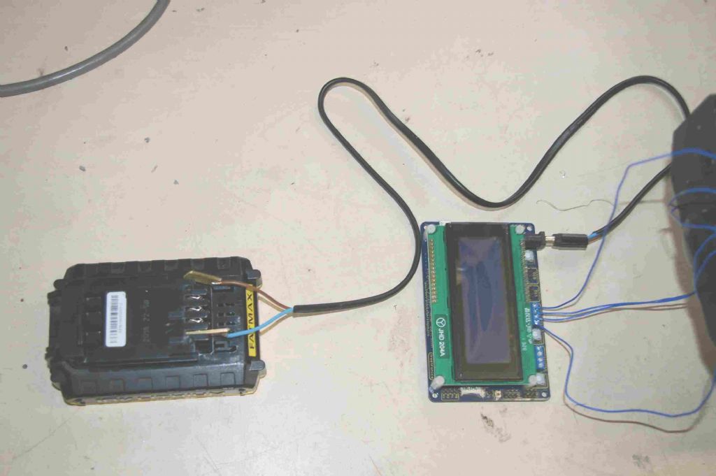
                      As I understand it, I'll need to provide an external power supply as the USB supply hasn't got the power required. I was intending to use the spare battery for my drill which is 18V. Is this OK? From what I can gather, the Input voltage can be 7 – 28V.

                      Can this power supply be connected when the Stepduino is connected to my PC via the USB port? I need the USB connection to download a sketch which will start to operate as soon as it is uploaded which will need the external power supply.

                      Do you know what the display screen is for? I can't see the point of it.

                      I may have made a mistake getting a StepDuino instead of using a basic Arduino with the required add-ons. There is virtually nothing around explaining how to use the StepDuino but heaps of information on how to run stepper motors using an Arduino.

                      If I can get the external power supply sorted out I may be able to run one of the sample sketches on the Freetronics website and maybe proceed from there.

                      Regards,

                      Alan

                      #377369
                      Michael Gilligan
                      Participant
                        @michaelgilligan61133

                        Alan,

                        I had not heard of the StepDuino until I saw this thread, but it looks to be quite well documented on the freetronics site: **LINK**

                        https://www.freetronics.com.au/pages/stepduino-quickstart-guide#.W9AlTtHTWhA

                        MichaelG.

                        Edited By Michael Gilligan on 24/10/2018 08:59:15

                        #377387
                        John Haine
                        Participant
                          @johnhaine32865

                          Alan, to make the stepper driver work as it should you need to supply it with a higher voltage than 5V. In the schematic they show it connected to 12V, but the quickstart guide says 7 – 28 V and there is a switched mode PSU to derive +5 V for the logic. So 18 V should be UK.

                          Yes you can connect the higher voltage supply while the unit is connected to your PC.

                          IMHO for your purpose the Stepduino is difficult to use as it has TWO AVR processors. One handles comms via USB and probably other stuff, the other the stepper motor itself and the display. I don't know anything about the Stepduino other than what it says in the quickstart guide and from reading the schematic. Personally I'd use a standard Arduino and the off the shelf design from MEW.

                          The display is needed since if the controller stands alone it needs an MMI to control it.

                          #377517
                          Alan Charleston
                          Participant
                            @alancharleston78882

                            Hi Michael,

                            I've been to the Freetronics site but for a beginner like me it's not much use. I bought the Stepduino because I thought it would be easier to use for controlling a steeper motor because that's what it is designed to do. That doesn't seem to be the case.

                            Thanks John. I think I'll try hooking up the battery and using the sample sketch on the Freetronics website. If it works I'll have at least managed to get a stepper motor shaft to turn which will be a great leap forward. After that I think I'll use my standard Arduino and follow the multiple tutorials around on how to run stepper motors.

                            Thanks again,

                            Alan

                            #377518
                            Michael Gilligan
                            Participant
                              @michaelgilligan61133
                              Posted by Alan Charleston on 24/10/2018 23:57:39:

                              Hi Michael,

                              I've been to the Freetronics site but for a beginner like me it's not much use. I bought the Stepduino because I thought it would be easier to use for controlling a steeper motor because that's what it is designed to do. That doesn't seem to be the case.

                              .

                              I think you're right, Alan

                              I only pointed you to that page because (a) you already have the board, and (b) it seems to answer several of the questions that you asked.

                              StepDuino is probably ideal for those who want to develop interactive, multi-axis gizmos; but for what you are doing, I think John is right [best to just use an Arduino].

                              MichaelG.

                              #377524
                              Alan Charleston
                              Participant
                                @alancharleston78882

                                Hi again,

                                Thanks to Michael and John.

                                I've managed to get the shaft of the stepper motor to spin using the example sketch shown on the Freetronics website!

                                The sketch wouldn't compile but I think the problem was at the end of the sketch where there was a section which froze the shaft in one position. I deleted that part of the sketch and the bit that was left which turned the shaft one revolution forward followed by one revolution in reverse compiled OK.

                                I had a bit of a hiccup when connecting the motor to the controller. There are six wires coming from the motor so it can be used as a unipolar motor. The controller has only four connectors so the motor needs to be connected in bipolar mode. I assumed that the centre tap wires would be ignored but the motor data sheet showed the connections to be from the centre taps to one end of each of the windings for bipolar operation. I tried this and the motor just buzzed so I connected the ends of the windings and left the centre tap wires loose. The motor then did what it was supposed to and rotated back and forth. I had a bit of a play with the sketch and changed the speeds.

                                Anyway, at least I've got the motor to turn, I know the motor works and how to connect it to a controller so I'm making progress. I think I'll take John's advice and revert to using a standard Arduino for the time being. When I get more proficient I may be able to make use of the Stepduino.

                                Regards,

                                Alan

                                #377528
                                John Haine
                                Participant
                                  @johnhaine32865

                                  Sounds like good progress Alan. You can get standalone stepper drivers ready mounted on pcbs for not much.

                                  #377530
                                  John Haine
                                  Participant
                                    @johnhaine32865

                                    Like this one.

                                    **LINK**

                                    #377705
                                    Alan Charleston
                                    Participant
                                      @alancharleston78882

                                      Hi John,

                                      I think I've come up with a working digital dividing head. I stripped out most of the Freetronics example sketch, leaving me with only the instructions required to run one motor a specified number of steps in one direction. The modified sketch is:

                                      const int Stepper1Step = 5;

                                      const int Stepper1Direction = 2;

                                      const int StepsPerRev1 = 4800;

                                      /**

                                      * Set pin assignments

                                      */

                                      void setup() {

                                      pinMode(Stepper1Step, OUTPUT);

                                      pinMode(Stepper1Direction, OUTPUT);

                                      }

                                      /**

                                      * Main loop

                                      */

                                      void loop() {

                                      for(int i = 0; i < StepsPerRev1; i++)

                                      {

                                      stepper1Forward();

                                      }

                                      delay( 1000 );

                                      for(int i = 0; i < StepsPerRev1; i++)

                                      delay( 1000 );

                                      }

                                      /**

                                      * Rotate stepper 1 forward by 1 step

                                      */

                                      void stepper1Forward()

                                      {

                                      digitalWrite(Stepper1Direction, HIGH);

                                      digitalWrite(Stepper1Step, HIGH);

                                      delayMicroseconds(500); // 1uS minimum pulse duration for DRV8811

                                      digitalWrite(Stepper1Step, LOW);

                                      delayMicroseconds(100);

                                      }

                                      I slowed it down by increasing the pulse duration to 500 uS and set the motor to rotate 3 revolutions by setting the steps/revolution to 4800. I disconnected the USB connection to my PC and the external 18V supply to the controller. I found that when the external power supply was reconnected, the stepper motor rotated three revolutions and stopped. This is what is needed to turn my dividing head.

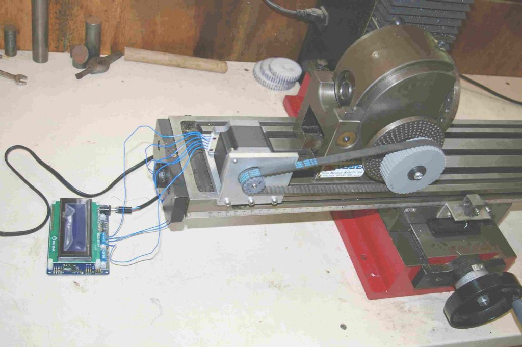
                                      I connected the motor to the dividing head using a toothed belt and a 15 tooth pulley on the motor and a 45 tooth pulley on the dividing head. The gearing in the dividing head is 40X so the three revolutions of the stepper motor resulted in the dividing head rotating 9 degrees. I've included a couple of photos of the setup.

                                      There is a indexing plate on the head with holes every 10 degrees which can be engaged by a pin on the main body. After setting the dividing head to 0 degrees, I applied the power to the controller from the battery 10 times and found the pin engaged the indexing plate perfectly at 90 degrees. The same thing happened at 180, 270 and back to 0 degrees again so the stepper motor is as accurate as the indexing plate.

                                      This setting enables a 40 tooth gear to be cut. I can of course change that to any number of teeth I want by connecting the Stepduino to my PC and changing the number of Steps/Revolution in the sketch. This is probably not much more time consuming than setting it using the LCD screen with all the complications with the sketch and the hardware this would entail.

                                      One thing worries me a bit. Given that it takes 1600 pulses to rotate the stepper motor 1 revolution and the gearing between the stepper motor and the business end of the dividing head (120:1) it requires 192,000 pulses to rotate the work one complete revolution. If, for example, I wanted to cut the ever popular 127 tooth gear, the number of steps/tooth required would be 1511.8 pulses. As the input to the sketch needs to be an integer, the StepsPerRev would need to be set at 1512. 1512 X 127 = 192,024pulses which is 24 pulses too many. This doesn't sound much but is 1.6% of the 1512 pulses/tooth. In other words, the final tooth will have 1.6% of its thickness removed and this will be worse if multiple passes are made when cutting a gear or if the decimal is closer to 0.5 rather than the .8 in this example.

                                      One way around this would be to cut 103 teeth at 1512 StepsPerRevolution, then cut the remaining 24 teeth at 1511 StepsPerRevolution which would reduce the error to 0.07% for the last 24 teeth which is probably negligible. This can be done by reprogramming the sketch after cutting 103 teeth or, since I have the dual output stepduino, reactivate the Stepper Two output with the StepsPerRevolution set at 1511. After cutting 103 teeth the motor would be unplugged from output one and plugged into output two.

                                      I hope this crude way of doing things doesn't cause too much offence.

                                      Regards,

                                      Alan

                                      divhead1.jpgdivhead2.jpg

                                      #377711
                                      Joseph Noci 1
                                      Participant
                                        @josephnoci1

                                        And therein lies the Devil!

                                        There are two typical ways to cope with this dilemma.

                                        To make the error as small as possible you would want to increase the number of stepper pulses per blank revolution. This either by increasing the gear ratios considerably, or by increasing the stepper controller microstepping count. The latter with the disadvantage that the stepper torque diminishes considerably when microstepping. Already at 1600 microsteps the torque is well down from full step mode, so lost steps become an issue.

                                        Increasing the gear ratios is better, as torque is multiplied, so maybe a balance between increased microstep count and greater gear ratios.

                                        I understand from your setup you are not doing continuous rotation hobbing, ie, the blank just indexes from position to position and halts each time, so stepper max RPM is not an issue.

                                        However, with microstepping, and esp when increasing the microstep count, you may need to apply an acceleration profile to the command index so as to not loose steps due to poor motor torque.

                                        The 'normal' or better approach to the integer issue is to 'spread' or interpolate the error evenly over the full index profile – crudely put, for your example above:

                                        For 127 teeth, cut 2 teeth at 1512 pulses, then 1 tooth at 1510 pulses, and repeat – this gives 84 teeth @ 1512 pulses interspersed with 42 teeth at 1510 pulses, with a last tooth cut at 1512 pulses. The error per tooth will then be between 0.8 and 1.2 stepper pulses, spread over a 1:2 ratio.

                                        Again, this is a crude representation of a typical DDA algorithm – Google the DDA and you should get a good understanding of its application.

                                        In essence – View the stepper motor individual steps as a staircase, starting graphically at x=0, y=0.

                                        The X axis represents 0 to 192,000 steps ( the steps required for a full blank revolution).

                                        The Y axis represents actual steps given to the stepper, ie, an increment in Y is a step pulse, no increment, the stepper stays where it was. The DDA generates outputs which then give the step or no-step command.

                                        If you zoom in on the slope of the line in this mental graph, you will see steps, like a staircase – however, you will see anomalies in the step shape – some risers will be more than one step tall, and some treads will be more than one tread long. This pattern repeats at regular intervals, spread evenly over the full 192,000 steps.

                                        You may need to massage it a little for your specifics, but it works well. Basically it is simple linear interpolation, and is used in many applications, a useful one being an Electronic Leadscrew for lathes. It is also used in the CNC world – to move the tool to a specific place at constant velocity in both x and y axes – but I digress..

                                        If you hack it, spread the error over the full blank, not over a few teeth at one end – else the gear will impose the same error on the driven leadscrew on your lathe, and on any thread you cut with it – a cyclic wobble..

                                        So, if the need is to cut a small handful of gears, hack it, but if the need is one of challenge , DDA it!

                                        Joe


                                        Edited By Joseph Noci 1 on 26/10/2018 08:39:05

                                        #377717
                                        Joseph Noci 1
                                        Participant
                                          @josephnoci1

                                          Alan, a little more thought yields a better approach – The DDA algorithm is in fact better suited to CNC applications, where two or more axes are driven from a specific point to another endpoint. The strength of the DDA is the generation of the stepper pulses at frequencies that ensure the axes, and thereby the cutting tool, move at constant velocity, that is, constant feed rates. – needed when cutting metal!

                                          A better method is Bresenham's line draw algorithm. This is in fact the way I did my Lathe ELS system.

                                          My description of the staircase alone the line's slope holds for Bresenham's as well and will sort your issues out elegantly.

                                          Joe

                                          #377751
                                          SillyOldDuffer
                                          Moderator
                                            @sillyoldduffer

                                            First, I wouldn't be too quick to discard the StepDuino. Looking at it, it seems to be no more than a board consisting of an Arduino Uno clone with two built-in stepper drivers, an SD-Card slot, and an LCD Display. You could assemble the equivalent from an actual Uno and the equivalent modules, but StepDuino does all that for you.

                                            The SD-Card, second stepper driver, and LCD display are all features. If you don't write code to explicitly use them, they will be ignored.

                                            Given that Alan started with an unknown motor, I suspect his problems are more to do with wiring it up and getting its parameters right in the code than a fundamental problem with Stepduino, especially as he has made progress with it. May not be a good idea to hack lumps out of Freetronics examples. Generally with computers you have to proceed logically. It's not like fault finding a mechanical problem where poking about often flushes out what's wrong.

                                            Secondly, dividing error. Joseph's suggestions are most interesting. I have my own stepper software, and am up for improving it if it's worth the effort. But is it?

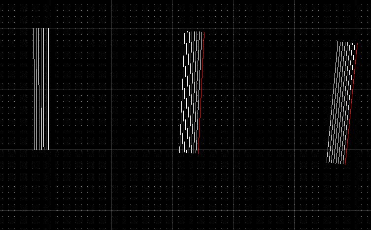
                                            Here's a perfect 127 'toothed' 100mm diameter circle:

                                            metric127errorperfect.jpg

                                            This is the same 127 'teeth' generated from 8 turns with Alan's rounding error (1512 for 1511.8)

                                            metric127errorx8.jpg


                                            In the second image there are still 127 'teeth' but the lines are thicker because the 'cut' is displaced slightly each time the wheel is rotated. Zooming in shows that the effect of the error is to turn the whole gear in a negative direction.

                                            metricerrorzoom.jpg

                                            Whilst the gear isn't perfect, the error doesn't accumulate at one end! Rather it is distributed around the entire gear wheel. My question is, does this matter in practice? Also, are the errors due to step rounding any worse than the errors that occur during cutting with a conventional dividing head?

                                            Dave


                                            Edited By SillyOldDuffer on 26/10/2018 12:11:13

                                            #377760
                                            Michael Gilligan
                                            Participant
                                              @michaelgilligan61133
                                              Posted by SillyOldDuffer on 26/10/2018 12:06:35:

                                              Here's a perfect 127 'toothed' 100mm diameter circle:

                                              metric127errorperfect.jpg

                                              .

                                              An excellent post, Dave yes

                                              But one question, if I may be so bold: … In what sense is that division 'perfect' ?

                                              So far as I am aware, very little to do with circles can be perfectly represented in the digital domain.

                                              MichaelG.

                                              #377765
                                              Joseph Noci 1
                                              Participant
                                                @josephnoci1

                                                Whilst the gear isn't perfect, the error doesn't accumulate at one end!

                                                That is true in part; the error is added to each subsequent tooth, not just to the end, but the net effect is as Alan describes – Imagine cutting 100 teeth of 1mm pitch onto the periphery of a blank 100mm in circumference. If you rotate the blank precisely 1 circumferential mm all the teeth fit fine, and start and end are in place. But step , to exaggerate, 1.1 mm, and the Final Cut ( Floyd, again..) will destroy the first few teeth.

                                                The first tooth is in place – zero steps, the second is at 1.1mm from that, the third 1.1mm from the second and so on. The hundredth ( 100 teeth worth of stepper steps..) tooth is 100*1.1mm from tooth zero – 110 mm, instead of at 100mm, ie, back at tooth zero . So we just destroyed the first 10 teeth..

                                                Obviously I have exaggerated the step per tooth error grossly to illustrate the point, and that is the effect of Alan's current integer problem – pedantic perhaps, since thinning the last tooth ( remember its opposite flank was cut in the first cut and so fixed in place) by 1.6 percent is probably irrelevant for the intended use. I have not checked the math to see if the 1.6% is correct – seems low at first , but if correct, ignore it perhaps.

                                                The spread of the CONSTANT error is not the (only) problem – the final end point is – all the errors have added to themselves along the way.

                                                The effect is made worse if the blank does more than one rotation – the error simply adds the integer excess onto the last position so it will accumulate all the way, thinning every tooth as it goes, UNLESS Alan's software can reset the pulse generator count accumulator back to zero at the zero tooth position, in which case the errors remain the same for each blank rotation.

                                                Interpolation such as with Bresenham's still spreads the error, but adds or subtracts it from the pulse stream so that it does not accumulate sequentially on itself. At some point the count error with be fractionally ahead, then behind, and occasionally spot on.

                                                Joe

                                                Edited By Joseph Noci 1 on 26/10/2018 13:07:30

                                                #377766
                                                SillyOldDuffer
                                                Moderator
                                                  @sillyoldduffer
                                                  Posted by Michael Gilligan on 26/10/2018 12:44:01:

                                                  Posted by SillyOldDuffer on 26/10/2018 12:06:35:

                                                  Here's a perfect 127 'toothed' 100mm diameter circle:

                                                  metric127errorperfect.jpg

                                                  .

                                                  An excellent post, Dave yes

                                                  But one question, if I may be so bold: … In what sense is that division 'perfect' ?

                                                  So far as I am aware, very little to do with circles can be perfectly represented in the digital domain.

                                                  MichaelG.

                                                  I've got a good lawyer, and he says I obviously meant this definition: 'loosely, To bring nearer to perfection' – as per the Shorter Oxford Dictionary.

                                                  Truth is, I've been rumbled again! The circle is far from perfect, it's an approximation.

                                                  A better description: the circle is the best that can be drawn in QCAD using ISO 60559:2011 double precision floating point arithmetic, but then it was crunched by me into a 1024×728 pixel JPEG image for storage on the forum. When displayed the Browser and the Forum rescale it again, on my big screen it appears at 495× 371 pixels, you probably see something different.

                                                  Sort of makes my point about rounding error though. If you can't detect the effects rounding may not matter.

                                                  Dave

                                                  #377772
                                                  John Haine
                                                  Participant
                                                    @johnhaine32865
                                                    Posted by Michael Gilligan on 26/10/2018 12:44:01:

                                                    Posted by SillyOldDuffer on 26/10/2018 12:06:35:

                                                    Here's a perfect 127 'toothed' 100mm ….

                                                    So far as I am aware, very little to do with circles can be perfectly represented in the digital domain.

                                                    MichaelG.

                                                    Or indeed in the analogue!

                                                    #377777
                                                    SillyOldDuffer
                                                    Moderator
                                                      @sillyoldduffer

                                                      Posted by Joseph Noci 1 on 26/10/2018 13:07:03:

                                                      The spread of the CONSTANT error is not the (only) problem – the final end point is – all the errors have added to themselves along the way.

                                                      The effect is made worse if the blank does more than one rotation – the error simply adds the integer excess onto the last position so it will accumulate all the way, thinning every tooth as it goes

                                                      Interpolation such as with Bresenham's still spreads the error, but adds or subtracts it from the pulse stream so that it does not accumulate sequentially on itself. At some point the count error with be fractionally ahead, then behind, and occasionally spot on.

                                                      Joe

                                                      Edited By Joseph Noci 1 on 26/10/2018 13:07:30

                                                      Thanks Joe, that makes sense.

                                                      While I was aware rounding can cause errors, I'd persuaded myself not to compensate for them on the basis that the effect would always be trivial in practice. Now I'm not so sure, particularly now you've pointed out that blanks may be cut with several rotations. If Alan's example were continued indefinitely, his teeth would be removed entirely, never a happy event!

                                                      While there are plenty of times when rounding error wouldn't matter, I think this is worth fixing. Once the algorithm is decided the Arduino doing a bit more arithmetic to compensate is neither here nor there, and far better that the user doesn't have to worry about the possibility of having his gears seriously thinned.

                                                      Not quite sure how best to go about it. Bresenham can't be applied directly as I understand it. I shall have to get my thinking cap on.

                                                      Problem:

                                                      Given a stepper motor, micro-step and gear ratio combination, and the requirement to divide by 'n', what is the best way of compensating for rounding error by finessing the number of microsteps taken to move a blank to the next division such that any error cannot accumulate. Hmmm.

                                                      This is why I never finish anything. I'm easily distracted and my 'to do' list is already 3 pages long…

                                                      Dave

                                                    Viewing 25 posts - 1 through 25 (of 50 total)
                                                    • Please log in to reply to this topic. Registering is free and easy using the links on the menu at the top of this page.

                                                    Advert

                                                    Latest Replies

                                                    Home Forums General Questions Topics

                                                    Viewing 25 topics - 1 through 25 (of 25 total)
                                                    Viewing 25 topics - 1 through 25 (of 25 total)

                                                    View full reply list.

                                                    Advert

                                                    Newsletter Sign-up