‘Stent’ T&C Grinder Queries

Advert

‘Stent’ T&C Grinder Queries

Home Forums Manual machine tools ‘Stent’ T&C Grinder Queries

Viewing 16 posts - 1 through 16 (of 16 total)
  • Author
    Posts
  • #717801
    Nigel Graham 2
    Participant
      @nigelgraham2

      I am presently engaged in completing a ‘Stent’ Tool-&-Cutter Grinder and have been preparing some new detail-drawings from the Blackgates-published drawings. I do not have any original text for this project – I bought it unfinished from a club-member who’d decided to go all-carbide. (Wealthy ‘erbert!)

      In preparing some decimal copies of the remaining details, the more I studied my now-fragile, yellowing copies the more puzzled I became.

      Quite a lot of these machines have been built, successfully too, and I have a copy of Model Engineer’s Workshop ((No. 108, Aug/Sep 2005) that shows a basic but major improvement by putting the wheel inboard of the column, nearer the table centre.

      Nevertheless, parts of the General Arrangement drawings are vague and there seem some peculiar things about the design!

      Has anyone built or bought one of these machines so can help me, please?

      .

      1) The Bearing Housing is designed as 3.00″ wide and hangs by a single 3/8″ diameter stud on a slide that is a full 3/8″ wider.

      The stud is well above the axis of the spindle so tilting the unit even a few degrees would move the highest and lowest points of the wheel considerably both horizontally and vertically. There is no degree-scale as is specified on other parts.

      There is no positive lock, second stud, rebate, dowel or other means either to set the assembly to tilt angle or to keep it horizontal.

      Why the different widths?

      Is the angle of the spindle designed to be adjustable out of horizontal, or not? I am not sure why it might, except perhaps for sharpening taps and reamers, but the plans do not suggest any such feature deliberately.

      .

      2) The GA apparently shows the motor mounting sandwiched between the Bearing Housing and Vertical Slide, sharing that one stud, with no positive way to ensure the motor and wheel spindles are, and stay, parallel.

      This assembly invites you accurately to fold 3″ wide X 1/8″ thick steel sheet into a channel 5″ across, and weld lumps of bar to it, without introducing distortions in the “sandwich” that would render the housing / slide alignment very inaccurate and liable to work disastrously loose.

      Can this be right? How is all that steelwork and motor held to the slide and/or bearing housing? Whether the spindle is intended to tilt, how do the motor and spindle stay parallel?

      .

      3) The Bearing Housing places two ball-bearing races in recesses in the casting, with the outer races abutting the bore profile and the inner races held to distance by a spacer the same length as the casting’s inner wall.

      That necessitates measuring the distance between two bearings to well within a “thou”, and making the Bearing Spacer to exactly the same length. Any difference could throw very unfair axial strains on the races as the unit is assembled.

      So how does one overcome that possibility? Is that inner spacer really necessary? (The axial load in service should be extremely small.)

      .

      4. The end-covers of the Bearing Housing “may” need cutting back to avoid fouling the Vertical Slide… It says that on the drawing! It will foul, by 1/8″, according to the drawing’s own dimensions. I suspect a mistake worked-round rather than corrected, but these covers hold something more important. Their inner diameter is not related to the shaft diameter. They are not bearings so should not be running fits, but there is a sizeable annular gap at the wheel end. The pulley end holds a bush that can be made to a close but loose fit.

      Why this gap? How does one stop grinding dust finding its way inside?

      I have for it two sealed metric bearings, 15mm X 35mm X 11mm, the size specified (by what looks like an addition on my copy, perhaps a later edition of the all-inches plan set), but have made my shaft too loose a fit. I am never quite sure where a bearing is meant to be gripped – every reference seems to have a different idea – but I will need make a new shaft, using 15mm silver-steel or stainless-steel so it fits properly, and fitting the wheel hub to that.

      I do  wonder how many model-engineers had equipment for such relatively heavy steel-fabrication as that motor mounting when this machine was published in the 1980s. I suspect very few do even now, other than builders of large-scale road steam vehicles; and most of the tooling offered to us by our regular suppliers is on its limit at only 16swg (1.5mm). I have heavier bar-benders, from WS Neal. If Blackgates offer these parts ready formed there is no hint of it on the drawings.


      Advert
      #717810
      noel shelley
      Participant
        @noelshelley55608

        Many standard series ball races eg 6205 though used in imperial equipment and machines going back over 50 years are of metric dimensions. Others may comment but I would  seek advice on the use of angular contact ball races. Noel.

        #717869
        JasonB
        Moderator
          @jasonb

          There is a long thread on here somewhere about milling spindles and placement of bearings and spacers

          #717893
          Nigel Graham 2
          Participant
            @nigelgraham2

            Thankyou.

            Noel –

            I didn’t know that but the way the bearings’ specification is written on the drawings’ own parts list suggests that the metric form was added after first issue. It’s not a problem as the casting was already bored out to take 35mm o.d. bearings, though not quite deeply enough.

            The difficulty is having somehow to ensure the two recesses are exactly parallel and co-axial, and you are hampered by the housing’s design. Luckily its original builder seems to have managed that.

            It is tempting to bore right though and seat the bearings against an insert, but this item is not designed for that, and it would give a thin wall on the load-bearing side. (Had the axis been placed 1/8″ further out, that may have been safe to do, and would have avoided cutting segments from the bearing covers, too.)

            I don’t think angular-contact bearings are necessary on this provided the bearings are properly in line. They seem to be using the shaft I have made, which is slightly too small so slides through the bearings.

            .

            Jason –

            Ah, a matter of finding it!

            I don’t think there is anything wrong with the basic arrangement, but the detail design makes it harder to achieve the necessary accuracy. (Or precision? I can never remember the difference!)


            #717895
            bernard towers
            Participant
              @bernardtowers37738

              Having made my Stent over 30 years ago I cant say i recall having the problems that Mr. Giles had, surely its just working on the other side of the wheel. In his configuration the the rotation of the wheel would have to be a/clock to stop grinding sparks going upwards!!!. In the original configuration which I built mine to has the wheel going cl/wise making the sparks go d/wards. As the design seems to be a baby Clarkson it cant be that bad can it?

              #717906
              Nigel Graham 2
              Participant
                @nigelgraham2

                The aim of turning the column and spindle assembly round is to centralise the grinding over the middle areas of the table and its slides. Yes, it may mean reversing the motor’s direction, but that should not normally be a problem.

                I have seen a Clarkson T&C grinder, on which the Stent is approximately based, but cannot recall its general arrangement, though it is a larger and more robust machine anyway.


                The MEW article was by a Mr. Parkes not Mr. Giles (he is Giles Parkes).

                He tells us how he had identified the source of accuracy problems as the original layout placing the tool being ground well over to the left. This creates a long table overhang not good for stability and accuracy.

                He is careful to say the modification was not his idea, but he had seen it already made on a Stent grinder at a model-engineering exhibition. Unfortunately, he admits, he did not note the exhibitor’s name so could not credit it properly.

                Mr. Parkes additionally arranged his example so the column can be turned back to as-original to enable using the circumference of the wheel, but adds not envisaging needing that very often. If I understand his photograph correctly he had made the spindle double-ended to allow that.

                His grinder also has a long, ball-ended handle on the bearing-housing stud, suggesting that the plane of the wheel can indeed be angled from its normal vertical. You’d need use a protractor, or fit the machine with a scale, to set it.

                One detail I picked up in his article is that the original design had bearings of differing diameters on the spindle. My edition, published by Blackgates in 1987, uses the same size both ends.


                #717949
                Bazyle
                Participant
                  @bazyle

                  Part of the fun is improving designs with the benefit of second sight.

                  1) The forces on the spindle are not like milling so a single bolt can work though perhaps a taper pin 90degree alignment might help. The bigger problem is the vibration & weight of the motor turning it. The slot size discrepancy if I understand you might be to accommodate a shouldered T-nut that the designer happened to use on his milling machine.

                  2)Many of the builders originally might have been able to do the bending at work but it also (going from pictures on lathes.co.uk) has weldments again often not regular ME equipment at the time. Easy enough to fabricate but I would attach the motor to the vertical slide block if not having it completely separate.

                  3)Inner spacer on bearings was common on cars and back in the day most makers would know about pick-off shims. Are these still around? Google didn’t immediately deluge me with hits.

                  4)The endplate is in a fixed position not screw-in so just file off a flat. Either make a secondary close fit brass disc attached to the endplate or perhaps a felt washer holder. It will pick up dust and grind a groove in the spindle over time but doesn’t really matter back there. (I think I have an obsession as I’m now thinking of 3D printing felt holders and I don’t even have a Stent)

                  #718036
                  Michael Gilligan
                  Participant
                    @michaelgilligan61133
                    On Bazyle Said:

                    3)Inner spacer on bearings was common on cars and back in the day most makers would know about pick-off shims. Are these still around? Google didn’t immediately deluge me with hits.

                    Occasionally, it helps to know a trade-name:

                    http://www.shimpack.com/shimlammetals.html

                    MichaelG.

                    #718054
                    bernard towers
                    Participant
                      @bernardtowers37738

                      No 2.  My motor mount was made from 3mm bright plate and the corners have 3/8 x 3/8 ms angle inside and riveted together the old fashioned way but does ensure no distortion. Angle was skimmed on mill to be square.

                      #718083
                      Nigel Graham 2
                      Participant
                        @nigelgraham2

                        Thankyou Bernard.

                        I was wondering about doing that, but I was not really clear just how this thing goes together and keeps its alignment where there seems a lot of heavy metal hanging off just one stud.

                        Perhaps the answer is to secure the plate to the back of the bearing-housing with 4 countersunk screws – they don’t need be very large – to maintain alignment, and as

                        Bazyle suggests,

                        also fit an alignment-pin for the normal position.

                        On Point 4) the drawing does indeed call for a flat on the bearing covers to cope with their overhang. This problem arises because they are 2″ diameter but the back of the bearing housing is 7/8″ from the axis.

                        I’m not clear what you mean by “slot size discrepancy”. The assembly is secured (ish) by a simple 3/8″ dia stud and ordinary nut – though adding a spring washer might by a good idea..

                        …..

                        I’ve not done anything about the motor mounting yet as that is pending obtaining a motor. Since the Stent was designed in or before the 1980s (the copyright date on the drawings is 1987) it’s just possible the modern versions of the 1/6HP motor (125W) specified might be smaller and lighter than available to the machine’s designer.

                        That’s a point – whom do we credit for designing it? He’s not named on the drawings.

                        Blackgates still sells the drawings and castings although with a significantly different arrangement that places the motor much closer to the vertical column, at some cost of extra height. The photograph in the down-loaded catalogue is poor but seems to show a rather better version of the bracketry too, so the machine has undergone refinements over the years.

                        That MEW article illustrates this pattern, built by A. S. Gray. His is of otherwise “standard” layout so the cutter-holder is on the end of the table, and completely overhanging the bed – though to be fair I think he may have moved it further than normal so as to show the wheel more clearly. Another difference is that his grinder’s table has just one T-slot, offset to the front. Mine has two, symmetrically disposed.

                        By contrast, Mr. Parkes’ Stent has its motor mounted quite low down and well out to the back of the machine.

                        However you do it leads to large cantilevered loads on the column, but they all seem to work very well!

                        #718586
                        elanman
                        Participant
                          @elanman

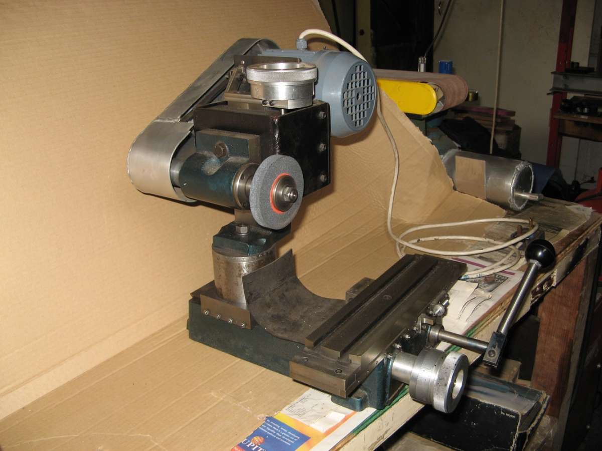
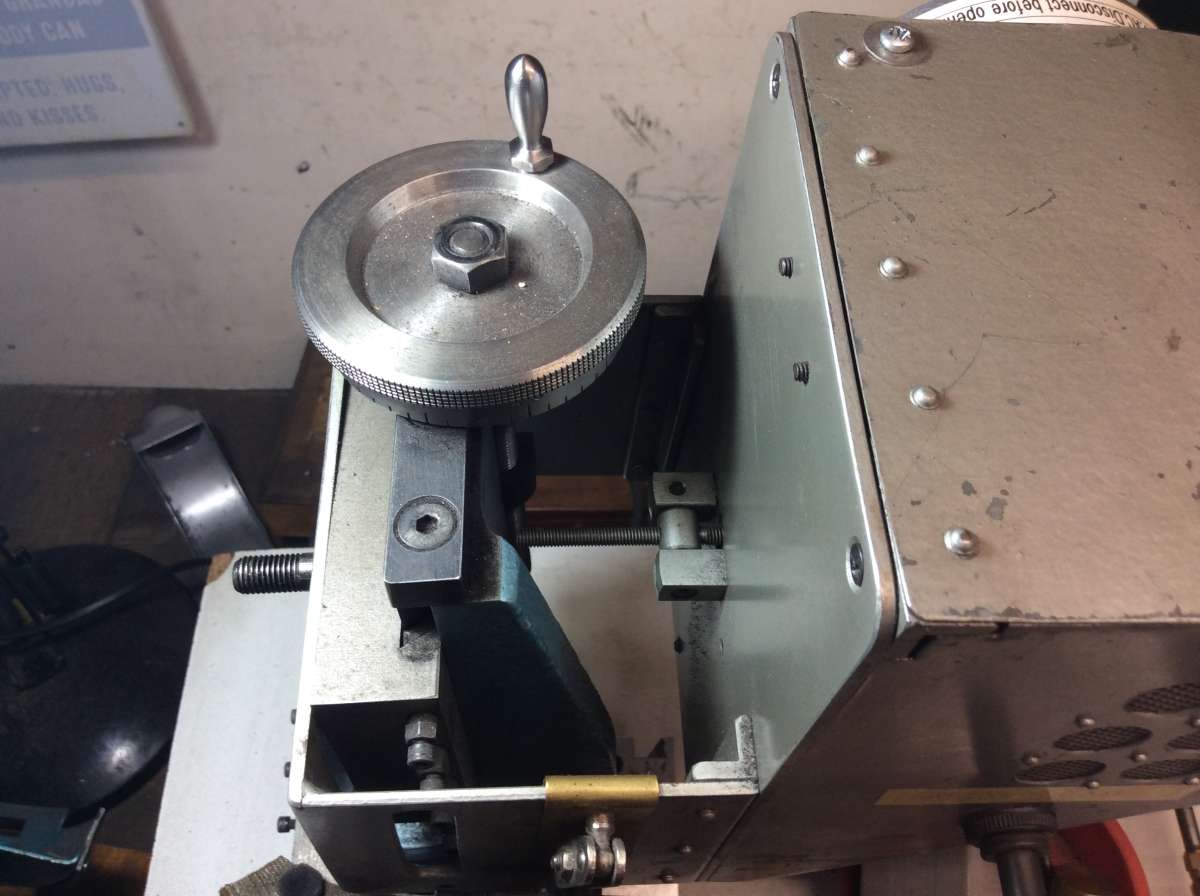
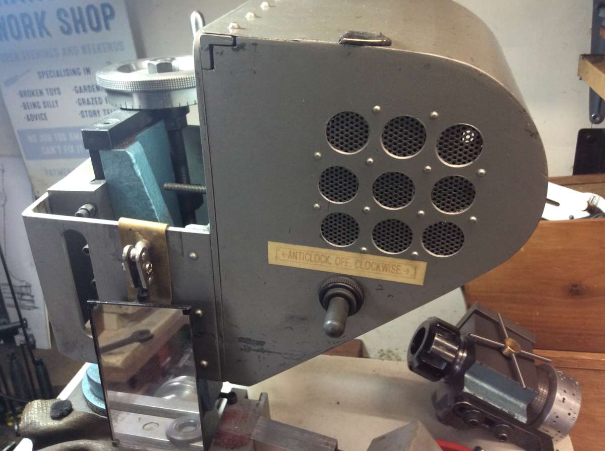
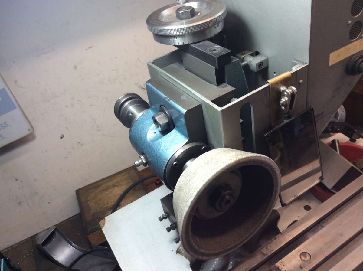
                          Here’s how I made mine. I have made a “box” that keeps the motor and spindle in line. Also a raising block to enable a magnetic chuck for ginding tappet shims and other thin plate.

                          Yes it can be made with the spindle to the left or the right of the column. Which is correct??

                          Cheers

                          John

                          IMG_0765rs

                          #718593
                          Bazyle
                          Participant
                            @bazyle

                            I think the original design was with the wheel on the left because it was a sort of copy of the Clarkson but that has the ability to slew the table round to the left of the column. So later builders thought it would be better on the right more above the main bed. However that is not necessarily good if you have a long tool mounted say in an air bearing on the right end of the table.

                            #718599
                            Nigel Graham 2
                            Participant
                              @nigelgraham2

                              John –

                              I would not like to say which is “correct”. It may depend on what you envisage sharpening.

                              As Bazyle says, the original does have the wheel to the left of the column but that can lead to the table having to be well over the end of the bed in ordinary use, so some constructors have reversed the layout so the wheel is roughly over the middle of the bed.

                              That right-hand version would probably suit most users, including me, sharpening ordinary milling-cutters, reamers and the like. If you are likely to be servicing more exotic tooling such as his air-bearing mounted ones, you might well want to modify the machine further to suit your own needs.

                              .

                              I note the protective rubber cover on your grinder. I have found butyl pond-liner good for this, having a sizeable piece left over from making luxury accommodation for my garden’s frogs. I used a piece rather as you have, on my milling-machine.

                              That’s a neat box for the motor mounting: a welded fabrication?

                              .

                              I am going for the right-hand version in completing my grinder, and made a couple of small parts tonight.

                              I also completed the Guide & Guide Arm – two pieces glued together. Well, glued if you don’t accidentally make them a bit slack as I had. Slight countersinking and peening, plus the recommended ‘Loctite’ , sorted that, then a light touch on the the lathe and some modest draw-filing gave it a tidy finish.

                              It then raised an interesting question.

                              I have assembled it to plan, but it is not symmetrical, and if I turn the column 180º from original, will the Guide assembly including its mounting-block then be all the wrong way round in the wrong place?

                              After waving it around the part-assembled machine I concluded the best approach is to carry on and assess what if any changes it needs, once all the major parts are together.

                              .

                              One detail that surprises me is the massiveness of the hand-wheels. These could probably be of aluminium alloy, and the steel ones as designed are very heavy lumps for what they do. I may hollow mine out more than they are, to reduce their weight a bit.

                              The 3/8″ x 20tpi screws seem a bit thin. I’m looking at using 1/2″ UNF which would keep the same 20tpi and hand-wheels, and not require significant alterations to anything else. The latter for I have already made them including the graduations, but not yet the numbers. I might have those engraved professionally rather than try to stamp them.

                              #718666
                              elanman
                              Participant
                                @elanman

                                Nigel,

                                “That’s a neat box for the motor mounting: a welded fabrication?”

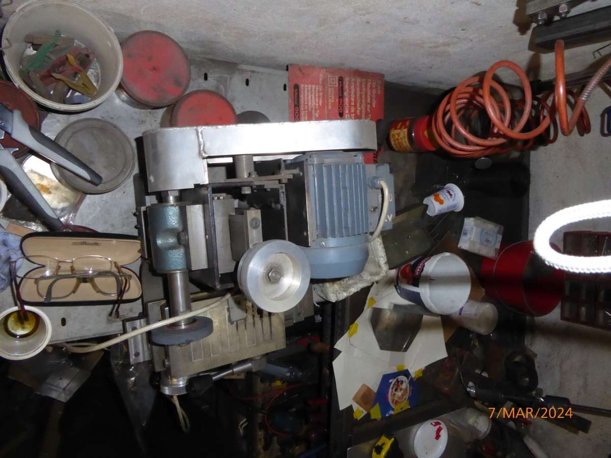
                                The U section is welded plate and the part across the top is a flat plate with angle bar welded each end to allow it to be bolted together. It is fixed to the spindle bearing mount by countersunk screws.

                                I also use a revesible motor and I have two spindles, one LH thread and the other RH thread. And another spindle which is extended to reach the mag chuck.

                                Here’s another pic from the top. And yes the bench does need a clear out!

                                John.

                                P1050969rs

                                #718722
                                bernard towers
                                Participant
                                  @bernardtowers37738

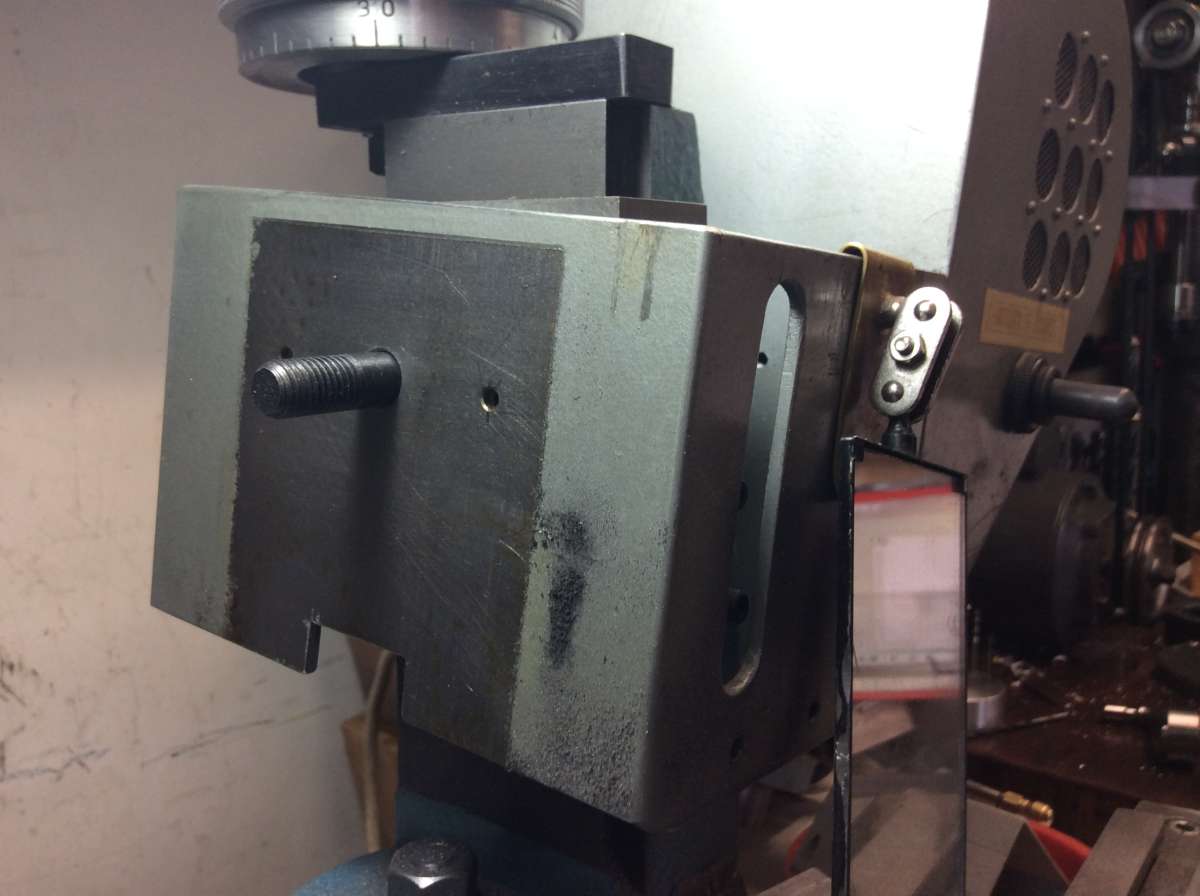
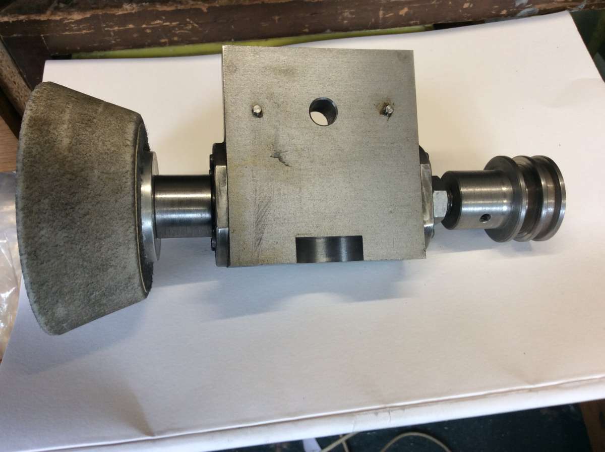
                                  Going back to my post on the 4th I said about using angle but mine only has angle on the right hand side (motor side) the left hand is sif bronzed to allow more tilt of the wheelhead if necessary . The bearing block has two pins added to keep the relationship between the head and motor.IMG_3486IMG_3485IMG_3487IMG_3488IMG_3489

                                  #719451
                                  Nigel Graham 2
                                  Participant
                                    @nigelgraham2

                                    That’s very neat and impressive work, Bernard!

                                    I now have the motor, sitting on the table on one side of the computer.

                                    The grinder is slowly taking loose-assembly shape on a stool on the side side.

                                    .

                                    The original design has the motor way out to starboard of the column, on the opposite side to the spindle and approximately level with it. As I am making mine with the central spindle, the motor will be off to port. That basic layout seems to make the machine very unbalanced with a large overhung load on the column mounting, so I see other you and other constructors have inclined the drive to bring the motor closer to the column.

                                    I’m catching up on finishing all the bits up to column-top, then once I have assembled the basic machine I can decide on how to mount the motor, and your approach is a valuable guide!


                                  Viewing 16 posts - 1 through 16 (of 16 total)
                                  • Please log in to reply to this topic. Registering is free and easy using the links on the menu at the top of this page.

                                  Advert

                                  Latest Replies

                                  Home Forums Manual machine tools Topics

                                  Viewing 25 topics - 1 through 25 (of 25 total)
                                  Viewing 25 topics - 1 through 25 (of 25 total)

                                  View full reply list.

                                  Advert