Hi chaps, from memory I bought two needle rollers with their external sleeves OD 1.625 inches. They were 0.625 ins long each and were a perfectly standard catalogue item at my local bearing factors.
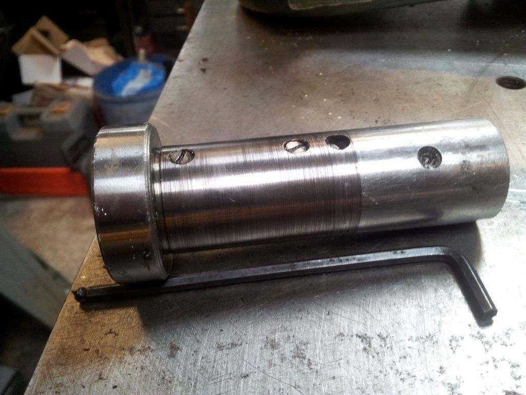
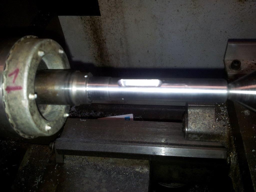
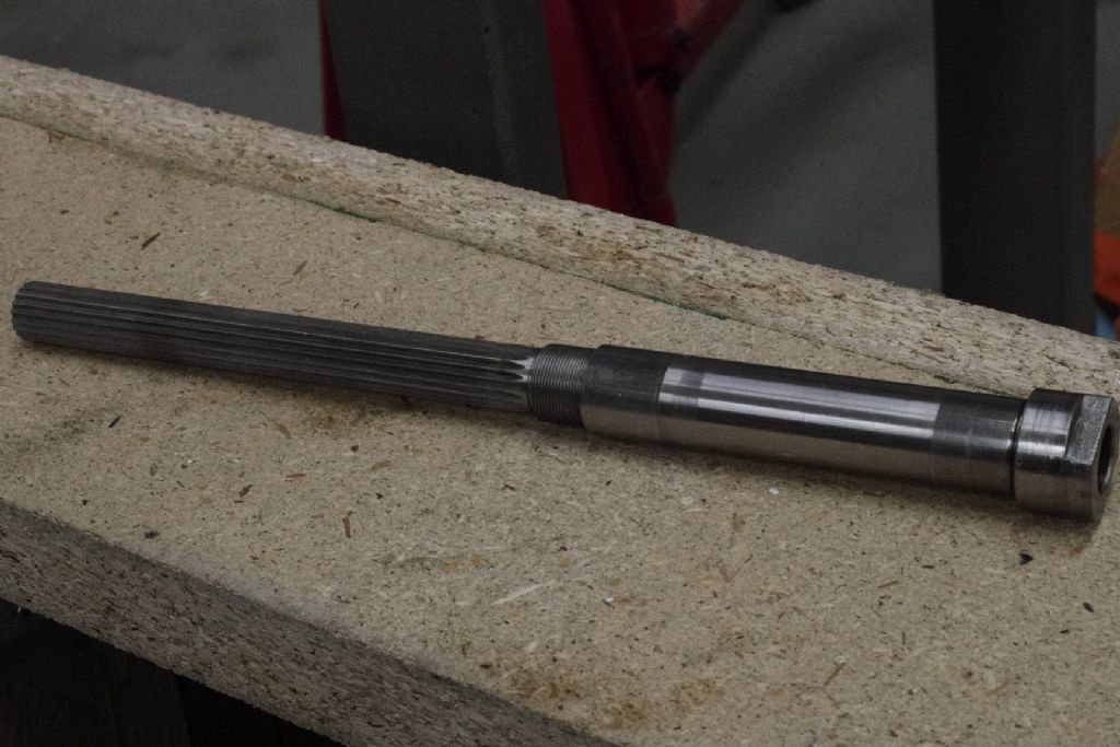
I also bought two matching hardened inner sleeves, the internal diameter of which was (from memory) 1.000 inch. I chose these because that was the outside diameter of the driver sleeve – with the key way up its middle.
All of these proprietary parts came from my local bearing stockist, but they had to be imperial dimensions because the starting point is that the hardened inner sleeve must be a snug fit over the original (damaged) drive sleeve.
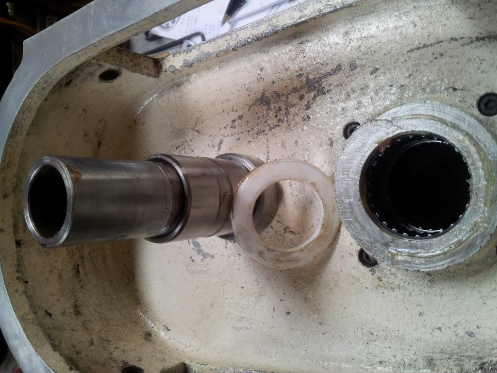
I then made a short spacer 1 inch ID by approx 1.3 OD and 0.25 thick which went between the two bearing inner sleeves to space them vertically, and a PTFE washer which was about 2 inches OD which went over the outside of the needle roller outer below the pulley to make sure the pulley and casing couldn't contact each other. This PTFE washer was about 2 mm thick, it had to be slim enough that the bearings were left with some endfloat when the driven pulley was correctly positioned on the drive sleeve. I know PTFE is self lubricating, but I greased this liberally on assembly. I can't remember what ID this washer was, but it was to clear the OD of the inner bearing hardened sleeve.
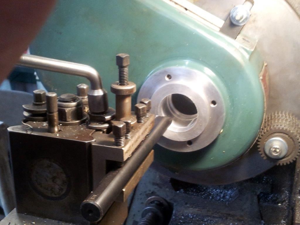
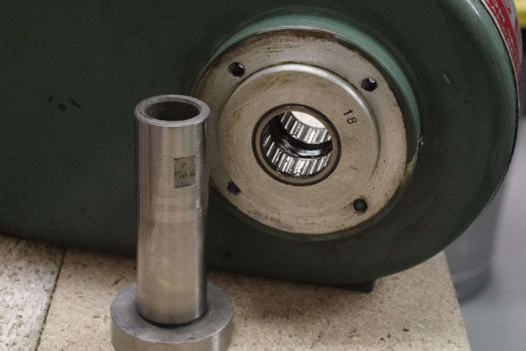
Now I bored out the original milling machine top casting to accept the OD of the bearing assembly – I wanted it to be a nice snug fit so bored it out to 1.624 as close as I could get it. This stage is shown in the pictures above.
Now I assembled the bits, bearing (no pun intended) in mind that the driven pulley is an interference fit over the drive sleeve and needed heat to expand the bore. The two hardened inner bearing sleeves were loctited onto the damaged outer of the driven sleeve (with the keyway up the middle) with the 0.250 thick spacer between them.
Pop the casting and driven pulley back on top of the milling machine head, and replace the motor, drive belt and anything else I've forgotton, switch on and admire.
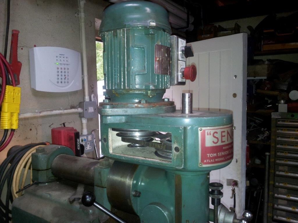
I rather fancy that the factory version of this as shown above uses a double row needle roller bearing, but I used two separate bearings with a spacer to get the same result. I didn't know that there was such a thing as a proper factory fitted bearing, I was making it up as I went along.
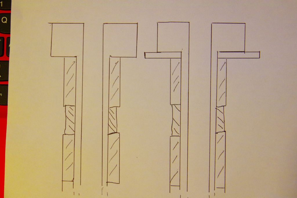
HTH, hopefully I kept some sketches of the bits I made in my notebook (and I can find them) so if they would help I go looking for them. It's all pretty obvious once you've got the bearings in your hand.
My modification is still going strong 3 years later, it's done quite a bit of work in the interim though I don't use it every day. I'm reluctant to take it to bits to see if it's holding up – it's not making any inappropriate noises so I've left well alone. I'm a sucker for taking this to bits to see how they work – and a devil for not quite getting round to putting them back together.
Best rgds Simon
Edit – The ID of the PTFE washer must have been a shade over 1.00 diameter as it only needs to clear the outside of the original driven sleeve, not the OD of the inner bearing as described above. My apologies.
Edit 2 – There is a circlip in the bore of the machined top casting to hold the bearing outers down so they can't "walk" upwards under load, and there must have been another 0.25 inch spacer in this bore between the two outer bearings, though I can't for the life of me remember making or fitting it. I hope I did!
Edited By Simon Williams 3 on 23/01/2020 19:36:25
Edited By Simon Williams 3 on 23/01/2020 19:39:37
Edited By Simon Williams 3 on 23/01/2020 19:41:39
old mart.


