Myford super 7

Myford super 7

Home Forums Beginners questions Myford super 7

Viewing 25 posts - 1 through 25 (of 26 total)
  • Author
    Posts
  • #121711
    Harry Wilkes
    Participant
      @harrywilkes58467

      Hi just joined a looking for a little advice not long aquired a Myford Super 7 and today I was looking at the lub points and on the diagram I have it show a lub point (12) as front shear point and (13) as rear shear point but I dont have No13 on my lathe on the rear of the saddle I have the bolt to clamp the saddle and one other hole which appears to be tapped 7/32 BSF (I think) and does't look if the nipple should fir there anyway.

      It's one of those little things that you must have a answer to so suggestiond please.

      #6741
      Harry Wilkes
      Participant
        @harrywilkes58467

        oil nipple

        #121726
        S Deakin
        Participant
          @sdeakin73134

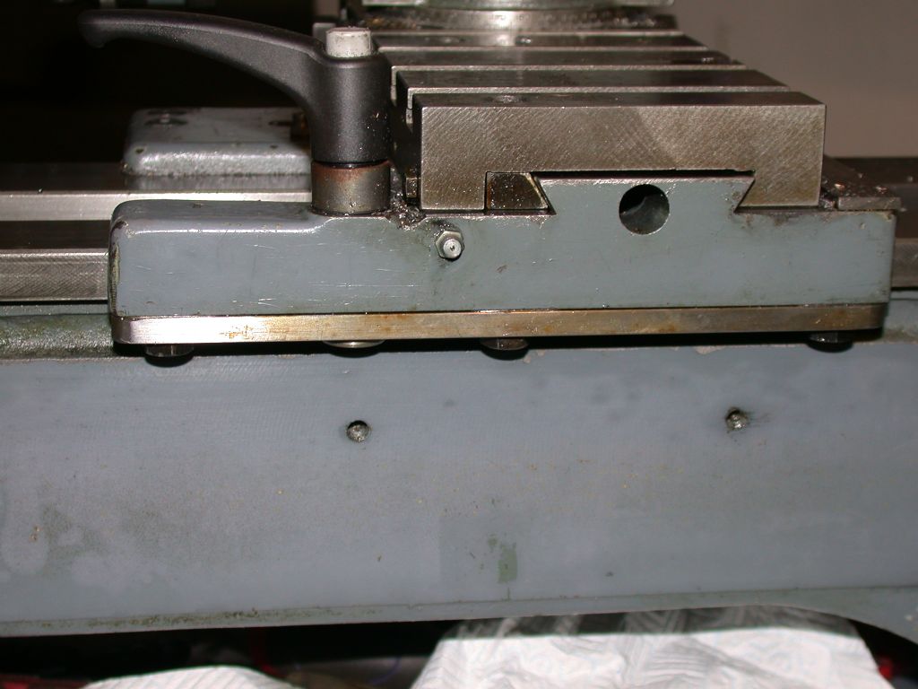
          Look around the rear of the saddle, with the cross slide wound towards you (if you are standing at the front of the lathe) until it gives a clear view of the vertical face of the saddle. There should be a nipple about four inches to the left from the rear shear right hand edge. If thats where you have a threaded hole, it should be 2BA. Nipples are available from Myford.

          #121760
          Robbo
          Participant
            @robbo

            To back up previous post, here is a pic of the rear of the saddle showing the nipple.

            Happen to have a S7 in part dismantled state on movable cabinet, so easy to take pic.s7 rear saddle.jpg

            #121813
            Harry Wilkes
            Participant
              @harrywilkes58467

              Hi and thanks for reply must admit I've been looking on the top of the saddle will look tomorrow for the one in your pic thanks for posting

              #121832
              Robbo
              Participant
                @robbo

                Harry, that other tapped hole on the top rear of the saddle is "spare". It's where they fix the coolant supply base when fitted at the factory. You can use it for what you like! Mine just contains a grub screw to prevent it getting full of gunge.

                #121851
                Robbo
                Participant
                  @robbo

                  The tapped hole should be ¼" BSF. If it seems to be 7/32", it's probably bunged up. Only us smart-arses plug holes when not in use!

                  Also, the hole is not present on all S7s, depends when they were made, earlier ones may be without it.

                  Find I can't edit the post after it's been up a while, or would have added this to previous.

                  #121859
                  Nobby
                  Participant
                    @nobby

                    Hi Harry
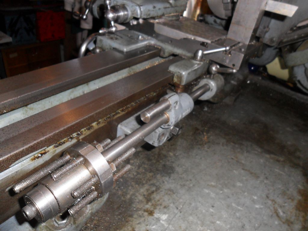
                    On my the S7 the tapped holes line up the casting to hold the 6  way stop i dont know if this helps
                    Nobby


                    6  position  stop

                    Edited By Nobby on 08/06/2013 12:40:07

                    #121866
                    Harry Wilkes
                    Participant
                      @harrywilkes58467

                      Hi Guy's many thanks for your replies have checked out the rear of the saddle as Robbo suggested there is a taped hole there but the grease nipple is missing, the hole is 2BA and quite deep about 1" into the saddle. the hole on top of the saddle could well be 1/4 BSFit is as suggested full of gunge !

                      Cheers H

                      #121873
                      roy entwistle
                      Participant
                        @royentwistle24699

                        Harry Please note it's an OIL nipple not a grease one

                        Roy

                        #121879
                        Robbo
                        Participant
                          @robbo

                          Can only emphasise Roy's post, it's an oil nipple, don't put grease in it, it won't get where it's needed and will bung up the oilways, needing a dismantle to clean it out.

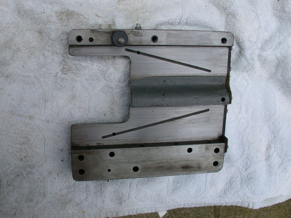
                          About 1" into the saddle is right for the oil hole, at it's end it meets up with another hole drilled from the underside of the saddle, at rt angles to the first one. This 2nd hole is in the middle of a channel milled into the underside of the saddle, diagonally across the width, so the oil is spread over the full surface between the saddle and the bed.

                          #121886
                          Harry Wilkes
                          Participant
                            @harrywilkes58467

                            Sorry guy's slip of the tounge like calling a vacume cleaner the hoover !!!

                            cheers H

                            #121961
                            Robbo
                            Participant
                              @robbo

                              Hi Harry et al,

                              Think we've beaten this one to death, but as I had the saddle off the S7 today thought I may as well include a shot to show the oil distribution.

                              Memory a bit faulty as to the location of the hole into the oil channel, but 'nowt new there.

                              dscn4802.jpg

                              #121967
                              Harry Wilkes
                              Participant
                                @harrywilkes58467

                                Thanks for the pic shows the oild distribution well smiley

                                Cheers H

                                #122013
                                Harry Wilkes
                                Participant
                                  @harrywilkes58467

                                  A couple more questions if it's ok to add onto this thread ! 1. am I correct in thinking the grub screws for adjusting the slide are 3/16 BSF, 2. I have a number of gears wheels and I,m wondering if I have a full set ? I have 30,35,38,40,45,50,60,65,70,75 there are two gear wheels on the 1st stud I have yet to identify so dhould I be looking for any more to make up a 'set' ?

                                  Cheers H

                                  #122024
                                  Harry Wilkes
                                  Participant
                                    @harrywilkes58467

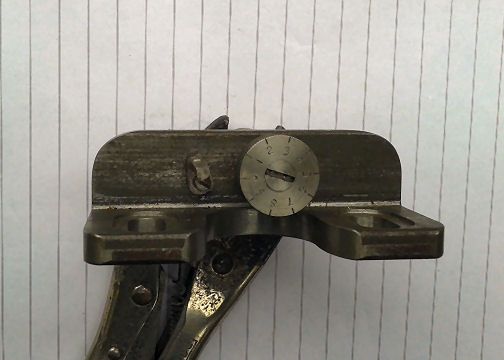
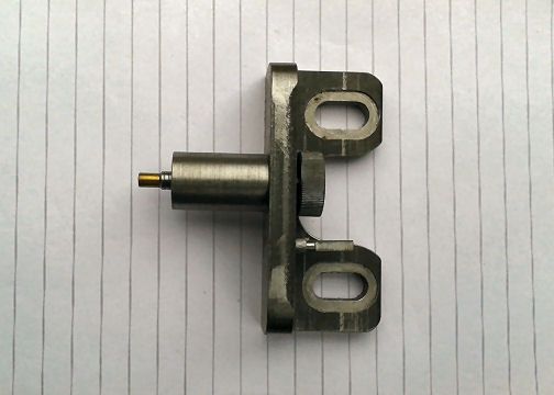
                                    found this part in box that came with lathe any idea what it is ?

                                    pic 3.jpgpic 2.jpg

                                    #122027
                                    Robbo
                                    Participant
                                      @robbo

                                      Hi Harry,

                                      The grub screws and lock nuts for adjusting the gib strip on the cross and top slides are 2BA, originally they were headless with a socket end, taking a 3/32" hex key. Modern replacements I have seen have slotted ends. Sometimes they get replaced with screws intended for the ML7, which are shorter, so there's no room ror the locknut. The screws on the saddle are 1/4"BSF.

                                      Change wheels: the normal set is of 14 gears, there are 2 x 20T, and one each of 25, 30, 35, 38, 40, 45, 50, 55, 60, 65, 70, 75, teeth. So you seem to be missing the 55T. In addition there is a 30T on the end of the spindle, which drives the three tumbler gears, 30T and 28T (I think, can't be sure without counting!)

                                      Phil

                                      #122051
                                      Sub Mandrel
                                      Participant
                                        @submandrel

                                        Hi Harry,

                                        That looks like a mcrometer stop of some sort.

                                        Neil

                                        #122056
                                        Harry Wilkes
                                        Participant
                                          @harrywilkes58467

                                          Phil

                                          Thanks for the reply need to check out the grub screws I have 2 that are longer than the others in so much as they protude out of the casting a 2BA nut will not screw on so I conclude they were BSF having (around) 32 TPI . I'll take one of the shorter ones out see if they are the same.

                                          Cheers H

                                          #122060
                                          Harry Wilkes
                                          Participant
                                            @harrywilkes58467

                                            think may have sorted it they could be the 'locking' screws AK30 AK31 which are M5x0. enlightened

                                            #122062
                                            Neil Greenaway
                                            Participant
                                              @neilgreenaway71611

                                              Hi there

                                              That item in your photo wouldnt happen to be the makings of a filing rest. Two rollers could be mounted on pins through the slotted holes with the pillar being mounted off the cross slide?

                                              Neil

                                              #122064
                                              Robbo
                                              Participant
                                                @robbo

                                                I think Harry's teasing us by having two views of the same thing in one picture.

                                                If the holes in the bracket match up with the slots in the cross-slide then I would go for a micrometer stop, especially if turning the dial makes that "sticky-out bit" (excuse technical term) move in and out.

                                                Phil

                                                #122527
                                                Harry Wilkes
                                                Participant
                                                  @harrywilkes58467

                                                  another quick question the thread dial indicator on my lathe is easily moved which as I plan to screw thread is of concern, it sits on a stud abount 1/4 " dia with a couple of fiber washers and a nut to tighten it. So is this setup the norm is it suspossed to be moved in and out of mesh when needed ? I have noted from pic on ebay the one Myford now supply as three small holes around the center one and the the write up they say supplied with fixing screws and firber washer ! Comments please

                                                  H

                                                  #122537
                                                  NJH
                                                  Participant
                                                    @njh

                                                    Hi Harry

                                                    Quite correct the TDI pivots on the bolt and can be moved in and out of mesh with the lead screw and held in position by tightening the nut ( with fibre washer underneath).

                                                    Cheers

                                                    Norman

                                                    #122538
                                                    Robbo
                                                    Participant
                                                      @robbo

                                                      Harry,

                                                      Second what Norman has said. If you tighten the nut the fibre washers will provide some friction, do it until it is just moveable by hand and it will be firm enough to stay in position.

                                                      Phil

                                                    Viewing 25 posts - 1 through 25 (of 26 total)
                                                    • Please log in to reply to this topic. Registering is free and easy using the links on the menu at the top of this page.

                                                    Latest Replies

                                                    Home Forums Beginners questions Topics

                                                    Viewing 25 topics - 1 through 25 (of 25 total)
                                                    Viewing 25 topics - 1 through 25 (of 25 total)

                                                    View full reply list.