Myford ML4 question.

Advert

Myford ML4 question.

Home Forums Workshop Tools and Tooling Myford ML4 question.

Viewing 18 posts - 1 through 18 (of 18 total)
  • Author
    Posts
  • #19127
    Nick Wood
    Participant
      @nickwood81857

      How to change the belt?

      Advert
      #379253
      Nick Wood
      Participant
        @nickwood81857

        Hello to all,

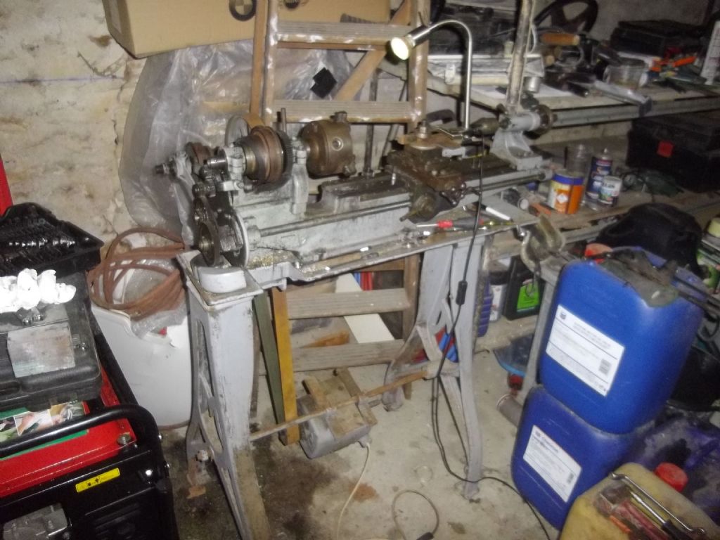
        I bought a Myford ML4 lathe and I wonder if there is a simple way to change the belt on it.

        First a picture of the lathe:

        imgp2415.jpg

        As you can see it's the model with the motor hanging under it.

        Now, I loosened up everything I could find but the spindle is not budging.

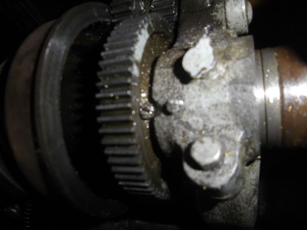
        Grub screws at the front side:

        imgp2417.jpg

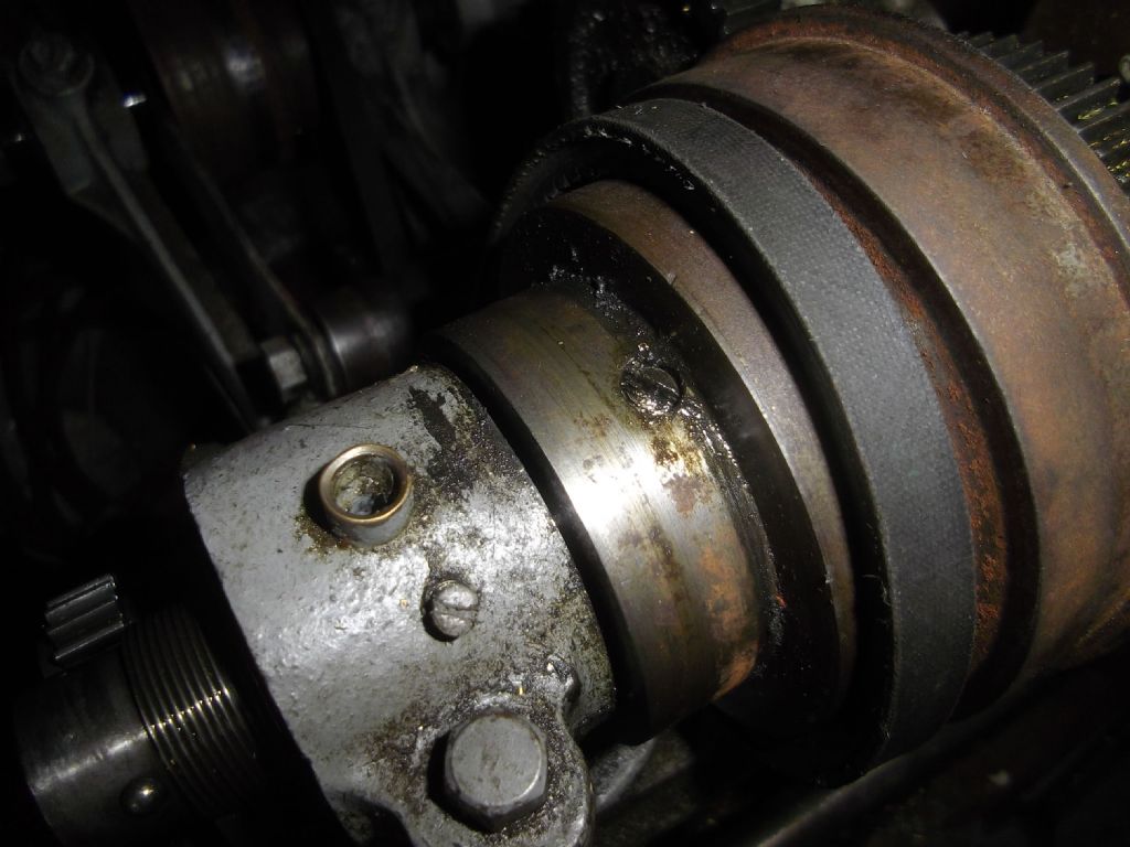
        Grub screws at the back side:

        imgp2419.jpg

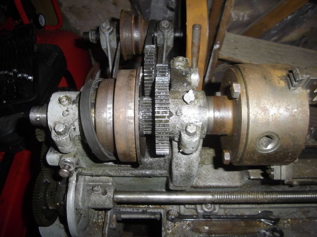
        And a picture of the whole gear:

        imgp2416.jpg

        What am I missing here?

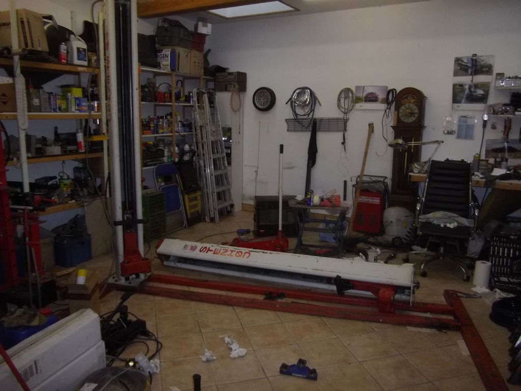
        Later on I will do a full restoration because I think it deserves it. For the moment it needs to produce some parts for my car lift which I'm restoring right now.

        imgp2420.jpg

        Any help and/or suggestions are very welcome!

        Thanks in advance,

        Nick.

        #379274
        Brian Wood
        Participant
          @brianwood45127

          Hello Nick,

          Make sure the motor is propped up to keep the weight off the spindle.

          Nip up the grubscrew for the 65T bull gear, engage the back gearing and take off the chuck, it will all be much easier with that added weight off the spindle. Undo that grub screw again and disengage back gear.

          Slacken the spindle bearing cap screws so that they no longer squeeze the bearings and with either a rubber faced hammer or wooden mallet tap the spindle forward from the change wheel end to withdraw it over the bed.

          That should be sufficient to remove it. Don't lose the thrust bearing or it's washer once it is out and remove the stepped pulley cluster as it comes free. There is a woodruff key linking the spindle and pulley bore and also needs to be pulled out, it won't go through the bull gear. A pair of nail pincers will extract it cleanly with a good grip and a little leverage from one side.

          After that the spindle is clear to pass through the bull gear and out of the chuck end bearing

          Regards

          Brian

          #379341
          Nick Wood
          Participant
            @nickwood81857

            Thank you so very much Brian!

            I figured out some things myself but your post was a big help.

            Now I just got one problem, the gear with the grub screw … this one:

            is stuck to the axle. I think the previous owner ran it without it being properly locked in place, from the friction possibly been produced it welded itself to the shaft. I can tell it was not locked by looking at the grub screw, it's worn on the top side telling me it was turned all the way out when he turned the power on.

            There is no way at this very moment I can get it loose. I do assume it has to turn free when that grub screw is loosened up.

            Please correct me if I'm wrong here.

            #379390
            Brian Wood
            Participant
              @brianwood45127

              Hello Nick,

              Oh dear. You are quite right in your assumption, the grub screw normally grips on a rather insubstantial flat on the spindle and the gear should be free to turn when the grub screw is loosened. With the gear having turned with the grub screw over-riding the flat the spindle will be chewed up to some extent below. The gear will not be welded on, it is in cast iron and the rough surfaces in contact are giving you the trouble you report.

              You can still knock it through, you will just have to grit your teeth and shut your eyes to do so !!

              Perhaps better might be to feed a length of studding [ all thread, I suggest M10 ] down the spindle to a thick washer at the change wheel end with an M10 nut outside it and find a suitable section of hefty tube to contain the nose of the spindle and at least a couple of inches more, fit a good section bridge with a hole for the thread over that and another M10 nut and use the arrangement as a drawbar to pull it through.

              Once the damaged section of the spindle is free of the gear you now need to protect the white metal bearing shell in the bearing cap as much as you can. I suggest you remove the clamp bolt for the bearing and push a wedge into the gap to spring the bearing open a little for added clearance. Be careful with this, the bearing caps are cast iron and will only tolerate a little of that treatment. Try if you can see the damage to align ridging with the gap in the bearing shell or if you can with a little flat Swiss file dress of the worst of it before to push or pull it through the bearing.

              Now you should be able to extract the spindle as I described before. The gear bore may well be jiggered but the spindle will dress with care to get the high spots down and it should be OK. I have a replacement gear if you need it

              Pictures please of the damage.

              Regards

              Brian

              #379401
              Nick Wood
              Participant
                @nickwood81857

                Thank you very much Brian, I will make a "pulling tool" like you suggested. I do have bearing puller for my BMW which may just do the trick.

                I'll make pictures of the tool and the process of getting the spindle out. I already loosened up the bearings, there is a nice bit of play available now so all should work.

                Many thanks!

                Nick.

                #379414
                Nick Wood
                Participant
                  @nickwood81857

                  Well …. That worked!

                  I had some M14 studding laying around which just fits, here it in inserted in the spindle with a big nut and washer at the end.

                  At the other side I placed a cap which is from my BMW bearing puller, fits perfectly as well.

                  Then started to pull.

                  I couldn't get the spindle to move using the ratchet, I had to call in help from Big Bad John.

                  Am I the only one who gives names to certain pieces of tools? Anyway, that worked but it was extremely tight.

                  Eventually it came out, you can see the mark on the shaft where the grub screw did some damage.

                  This is the inside of the gear.

                  I didn't measure the damage yet but it's very obvious I won't put it back together like that.

                  Here are pictures of the bronze bearings, seems quite fine to me. There was minor damage done to them by removing the shaft as far as I can see. The front bearing is in the second photo.

                  Well, that concludes this operation. Now I'm going to polish the shaft and see what I can do the that gear.

                  Again, many thanks for your help Brian! It's highly appreciated.

                  Nick.

                  #379421
                  Brian H
                  Participant
                    @brianh50089

                    Hallo Nico, you've probably already thought of this but I would bore out the gear and make up a sleeve with a through hole for the screw.

                    Brian (a different one)

                    #379426
                    Nick Wood
                    Participant
                      @nickwood81857

                      It crossed my mind Brian, I can run the lathe without that gear for the time being and just machine it. After that I can make a sleeve like you mentioned.

                      Thanks for the input!

                      Nick.

                      #379437
                      Brian Wood
                      Participant
                        @brianwood45127

                        Hello Nick,

                        Well done, it took more effort that I imagined it would

                        Fitting a sleeve to the damaged gear would work but it really needs pressing in and I would pin it as well, the bore should be a snug fit on the spindle which allows for rotation without slop as it is an important part of the back gearing for low speed turning when you need it. Brass would be better than a steel sleeve.

                        It's a long time since I owned an ML4 and I think I may have misled you with the presence of a Woodruff key. There isn't one on an ML4

                        The pulley cluster runs on the spindle when the grub screw in the smallest step in the cone is slackened and taking that grub screw out allows access for oil into the bore of the pulley cluster. The grub screw in the damaged bull gear should normally be screwed tightly into a dimple made in the spindle to receive the pointy end of it. Swinging the back gear cluster into engagement directs the drive from the pulley cluster through the back gear reduction and back to the spindle through the bull gear. The reduction is about 6:1 if I remember correctly

                        If you would rather replace the damaged gear, I have spares having made a few for sale [all to Myford spec]

                        Regards

                        Brian

                        #379462
                        Howard Lewis
                        Participant
                          @howardlewis46836

                          The Change Gears on ML4s and their predecessors are pinned (3/32 pins) and are easily damaged by trying to use them to lock the Spindle for removal of the chuck I made a few replacements for a friend who used to use this technique on his ML4.

                          Take a look at lathes UK website for ML2, 3, and 4 info. There is a specific warning about engaging Back Gear without loosening the Grubscrew, forecasting damaged gears if you do this to lock the spindle to remove a chuck.

                          This months M E W (274 ) has an article on a simple tool and way of locking the spindle on a the ML7 for chuck removal, without risk to the gears, and this could probably be applied in a similar manner to the earlier ML lathes.

                          Gripping a piece of timber or steel bar between the chuck jaws, and administering a sharp downward whack on the end of the timber often works as a fairly low risk means of slackening a chuck.

                          Another way is to grip a fair sized hexagon in the 3 jaw chuck, and apply a socket and a long bar, to slacken a sticking chuck. Again, a suddenly applied torque, via a mallet will be effective.

                          My 8 inch 4 jaw chuck has a 5/16 hole in the rear flange into which a bit of 5/16" silver steel, clamped to a piece of 1" x 5/16" x 12" flat bar is placed, ready for the impact of a copper/hide mallet. Has worked every time for the last 15 years!

                          Prevention is better than cure: make sure the threads, male and female are clean and undamaged, and don't spin the chuck on under power , or even fast by hand. Light lubrication may prevent rusting, if that is a concern.

                          Howard

                          #379466
                          Nick Wood
                          Participant
                            @nickwood81857

                            Hi Brian,

                            Absolutely! It took quite a bit of force to separate the spindle from that gear, having good tools around is an absolute must for me. Yesterday I understood knocking it out was no option, I hate hitting tools with hammers. Although I had a block of hard wood in between it I was very aware that it was the least favorable option. I could have slapped myself this morning when I read your suggestion to just pull it out. Why didn't I think of that myself? Anyway, I'm very happy you put me on the right track.

                            I polished up the spindle this afternoon and got it smooth for like 98%. That automatically means I had to take some material away. In case you wonder, no, I didn't get the groove out. That would have taken away far to much.

                            I think I will make a sleeve for the gear, I do have a 20-tonns press so getting it in place won't be a problem. Fact is the spindle has worn over the years and being it perhaps a few thousands of a mill I can make it fit perfectly again. I rather not use brass, temperatures in my shed/workshop can vary from below zero up to 40 degrees, having a different index on expansion and contraction I rather go for steel. Yes, there is a slight difference in between cast iron and mild steel as well but not as much.

                            I didn't pay any attention to whatever Woodruff key might have been in there, it was clear it had to come apart in a straight line so it wouldn't have made any difference. And no, I didn't find any.wink 2

                            I did put the headgear back together without that gear in place, it will most certainly be put back when I got time to fix it. Happy to say there is no slack in the bearings at all although the front one is on the limit of the gap to tension it. In other words, there is practically no gap left.

                            Measured up how long the belt I wanted to put on it (what this whole story started) and went to the local car parts supplier, bought a multi-rib V-belt (5 ribs and 910mm long) and installed it. De-greased the running faces on the lathe and the increase of torque is impressive!

                            I'm afraid you all have to wait for photo's till tomorrow because this afternoon I didn't take any.

                            Cheers,

                            Nick.

                            #379474
                            Nick Wood
                            Participant
                              @nickwood81857

                              Hello Howard,

                              Thanks for letting me in on your experiences. I just jammed a thin piece of scrap wood in between the gears and used my 6-foot crowbar to get the chuck off. It was not stuck on or anything, in fact it came loose quite easily.

                              I do understand one can damage things when real force is needed.

                              Thank you very much for sharing this!

                              Nick.

                              Edited By Nick Wood on 06/11/2018 17:47:04

                              #379478
                              Chris Trice
                              Participant
                                @christrice43267

                                I'd be inclined to bore out the bull gear and press in an Oilite bush with a hole carefully drilled in the right position for the grub screw. Obviously you need to clean up any burrs on the spindle before refitting but the surface area lost by that graunched groove is negligible. Being sintered bronze, an Oilite bush will be more gentle on the spindle and if it ever gets to a stage where it has worn to the point of needing replacing, you simply press a new one in.

                                #379484
                                Howard Lewis
                                Participant
                                  @howardlewis46836

                                  Hello Nick!

                                  I would be interested in any of your experiences with the ML4. Am trying to help someone who has bought a ML4 but with bits missing! He won't want to use the machine to its full capacity, but I want to help him to make it as versatile as possible, for minimum effort and cost. As he finds what can be done on it, he will gain confidence

                                  The Lathes UK website has answered one or two questions already, by showing what this casting with a steel pin sticking out was for. It should be bolted on to carry the missing cover for the Changewheels!

                                  One of the problems is going to be obtaining the BSW and BSF fixings that will be required, and then getting them to him from 140 miles away!

                                  Hopefully, between us we will make some of the parts needed so that he can do more work on it.

                                  Just to complicate conversations, he works in Metric, whilst I am a Luddite in Imperial!

                                  So any tips or information will be most welcome.

                                  The technique shown in MEW 274 for the ML7 was to drill/tap the Bull Wheel and fit a short capscrew. To remove the chuck, The capscrew is brought to bear against a steel bar extending to the mandrel. In this way the mandrel is locked without risking gear teeth, whilst torque is applied to the chuck. On the ML4, the risk is then to the grubscrew, but suitable relatively minor "fettling" can reduce the risk.

                                  Typical! You solve one problem and create another! But overcoming challenges is what makes the hobby so absorbing.

                                  Howard

                                  #379559
                                  Brian Wood
                                  Participant
                                    @brianwood45127

                                    Hello again Nick and Lewis [for information]

                                    I'm glad to have been of some help Nick, I rather suspect you are quite capable of solving them for yourself but if you need more help specifically for this old lathe please ask.

                                    I do still have a copy of the handbook and a whole bunch of new gearing tables I can make available. These cover a much wider range than the simple Imperial and metric set ups that Myford put in their handbook, the BA range 0-18 is covered for example, as well as DP and Module pitches

                                    Regards

                                    Brian

                                    #379865
                                    Nick Wood
                                    Participant
                                      @nickwood81857

                                      Brian, your help was highly appreciated and yes, I will ask if there is something I need to know. I will bear in mind you got spares, even beyond the standard stuff and a whole lot of info and experience behind you!

                                      Lewis, if I can be of any help just feel free to ask me things. Being it pictures of how it should be of whatever. I know very well what a lathe can do for you (me), on the other hand I'm not going to make pieces that are very complicated or are worth making the guinies book of records. I do work in metric myself but imperial is not an issue to me. The Myford ML4 is in imperial sizes and that's just fine with me.

                                      Anything I can do to help, please ask. Having said that, I think your best go is to ask Brian! He knows a lot more about this specific lathe than I do.

                                      Chris, I fully agree. I did polished the burrs and the shaft is as smooth as it should be. How do you say it? "As sweet as a baby's bum"? LOL!

                                      Yes, I rather go for an insert but in steel, keeping everything in the same kind of expansion rates while heating up or cooling down.

                                      The essence of this topic was to get the belt changed for a multi ribbed belt and I do owe you all a photo. Well… here it is!

                                      And an overview.

                                      This conversion, like I stated in a previous post, is giving me so much more torque! The main drive belt is not slipping anymore and the turning I have to do became so much easier. Yes, there is a piece of M14 sticking out. I just have to get the spacers which are going to be used to secure my car lift into the floor to size. The Myford ML4 works like a charm.

                                      Again, many thanks for helping me out!

                                      Nick/Nico.

                                      #379867
                                      Nick Wood
                                      Participant
                                        @nickwood81857

                                        Brian, you mentioned a speed decrease when the bull wheel is activated of something like 1:6, actually it's 1:5.9 – and – a -bit. So your memory serves you right.

                                        Edited By Nick Wood on 08/11/2018 22:52:42

                                        Edited By Nick Wood on 08/11/2018 22:53:07

                                      Viewing 18 posts - 1 through 18 (of 18 total)
                                      • Please log in to reply to this topic. Registering is free and easy using the links on the menu at the top of this page.

                                      Advert

                                      Latest Replies

                                      Viewing 25 topics - 1 through 25 (of 25 total)
                                      Viewing 25 topics - 1 through 25 (of 25 total)

                                      View full reply list.

                                      Advert

                                      Newsletter Sign-up