ML7 toolpost – Turns Under Load

Advert

ML7 toolpost – Turns Under Load

Home Forums Workshop Tools and Tooling ML7 toolpost – Turns Under Load

Viewing 25 posts - 76 through 100 (of 119 total)
  • Author
    Posts
  • #507464
    Dr_GMJN
    Participant
      @dr_gmjn
      Posted by Howard Lewis on 14/11/2020 15:17:30:

      Get rid of the spring, or you will never fix the problem.

      That spring cannot generate sufficient clamping force to lock the block, Even with the spring fully compressed, unless the ends have been ground flat, the force is likely to be off centre, so the result may be different each time.

      My fourway toolpost can be set in any orientation, and clamped with the handle, (No spring ) and stays in place, even with heavy cuts.

      I can see no reason why yours should be any different, if solidly clamped..

      Just to satisfy my curiosity, turn up a spacer, to replace the spring, and tell us what happens!

      Howard

      Howard, the spring was there purely to allow me to apply a consistent downward load and still be able to turn the holder slightly (for marking the blue). Rather than applying simultaneous pressure by hand and turning the block, I thought I'd try and remove one variable by letting the spring apply the downward load.

      I don't use it for clamping the block in use!

      Advert
      #507466
      Dr_GMJN
      Participant
        @dr_gmjn
        Posted by Nigel McBurney 1 on 14/11/2020 15:24:23:

        Just a thought,is the thread in the nut square to the locking face of the nut? I once a had a 1960s two stroke engined English built scrambler,it was s/h when I raced it for the first time the centre nut of the clutch kept coming loose,despite someh ard work in the paddock, later found the thread in the nut was not square to the faces,Brand new nut immediatley solved the problem. Various toolposts on my Super 7 have moved but only when taking things to and above the accepted limit, Knurling with single knurls will move a tool post even on my Colchester,though of course a big long ring spanner helps solve the problem,Also intermittent cuts act like an impact driver and will rotate a small toolpost,

        Thanks Nigel. I just checked that and its all good.

        #507470
        Michael Gilligan
        Participant
          @michaelgilligan61133

          Posted by Michael Gilligan on 14/11/2020 09:40:48:

          […]

          … I had always assumed that Myford faced that top surface in a lathe

          … That would certainly be my approach !

          .

          Clearly of no interest to anyone sad

          MichaelG.

          #507471
          Dr_GMJN
          Participant
            @dr_gmjn

            So I've flatted the sharp edges the best I can (I think it is indeed hardened), and chamfered the holes in teh casting.

            Here's what I don't understand about this:

            Block coated, clamped as per use (ie no spring!), to a tightness I can just turn the block a few degrees (pretty tight):

            so contact predominantly around the post.

            Then clean and repeat with the casting face coated:

            Same result:

            Clean, and double-check the first method by coating the block, and:

            Completely different result.

            Am I doing something stupid here?

            Do I just go with the last result, because if it was severely out of flat, I'd never be able to get that result, and assume its somehow my technique for blueing that's at fault?

            #507477
            Howard Lewis
            Participant
              @howardlewis46836

              The stupid thing was that someone inserted the spring before you got the lathe. A spring that is so spindly could never produce a load sufficient to stop the block rotating on the damaged surface that you had.

              Your last picture shows a much greater contact area.

              If you clamp the block with a fair degree of force, you may well find that a ) the block no longer turns under load, and b ) the surface finish improves.

              You now have a block which makes contact over a much larger area, showing that clamping force is what is needed.

              If the hole in the block is much bigger than the 7/16 BSF Myford stud, make up a top hat bush to centralise the block around the stud. (IF you don't have one ) The thickness of the "rim" should be such that with your spacer in place, and clamped hard, the handle does not overhang the workpiece., i.e. is on the operator side of the Top Slide. (Just another of my hobby horses )

              With the block tightly clamped, (You won't strip a 7/16 BSF thread with the forces that you can apply with just a hand )

              Hopefully, two of your problems will be history. Please confirm, when you have time.

              The spring can go into the "Come in handy one day" box to await a new career!

              Howard

              #507479
              duncan webster 1
              Participant
                @duncanwebster1

                photos as promised.

                img_3838 (small).jpgimg_3839 (small).jpg

                #507481
                Dr_GMJN
                Participant
                  @dr_gmjn
                  Posted by Howard Lewis on 14/11/2020 16:36:10:

                  The stupid thing was that someone inserted the spring before you got the lathe. A spring that is so spindly could never produce a load sufficient to stop the block rotating on the damaged surface that you had.

                  Your last picture shows a much greater contact area.

                  If you clamp the block with a fair degree of force, you may well find that a ) the block no longer turns under load, and b ) the surface finish improves.

                  You now have a block which makes contact over a much larger area, showing that clamping force is what is needed.

                  If the hole in the block is much bigger than the 7/16 BSF Myford stud, make up a top hat bush to centralise the block around the stud. (IF you don't have one ) The thickness of the "rim" should be such that with your spacer in place, and clamped hard, the handle does not overhang the workpiece., i.e. is on the operator side of the Top Slide. (Just another of my hobby horses )

                  With the block tightly clamped, (You won't strip a 7/16 BSF thread with the forces that you can apply with just a hand )

                  Hopefully, two of your problems will be history. Please confirm, when you have time.

                  The spring can go into the "Come in handy one day" box to await a new career!

                  Howard

                  There was never any spring in normal use – I explained that already.

                  #507487
                  Dr_GMJN
                  Participant
                    @dr_gmjn
                    Posted by Michael Gilligan on 14/11/2020 16:08:42:

                    Posted by Michael Gilligan on 14/11/2020 09:40:48:

                    […]

                    … I had always assumed that Myford faced that top surface in a lathe

                    … That would certainly be my approach !

                    .

                    Clearly of no interest to anyone sad

                    MichaelG.

                    Michael – please don't be offended. If I tried to take everyone's advice I would get nowhere. It's overwhelming, and occasionally contradictory.

                    One of my other threads (and yes, there are quite a few) outlines the refurbishments and checks I've been doing on the ML7 (wide-guide conversion, filing the bed etc etc etc). One of the checks is across the faceplate to ascertain perpendicularity with the cross-slide. Mine is 0.0005" out from the edge of the faceplate to the middle, convex – which isn't great. It may well be convex to such a small degree over the diameter of the topslide surface as to be insignificant, but anyway, that's why I didn't want to use the lathe for this.

                    I may have misunderstood something, or many things, but my reasoning is that since I knew my lathe could give a convex surface, I used the mill.

                    #507492
                    Les Jones 1
                    Participant
                      @lesjones1

                      Looking at the marks from the engineers blue in your post at 16:09 today the items are making contact more towards the centre. If the same clamping force was applied near the edge of the block it would have more effect at preventing rotation. I think I would be tempted to take a skim off around the centre of the tool post so that the edges were making contact.

                      Les.

                      Edited By Les Jones 1 on 14/11/2020 16:59:21

                      #507493
                      Dr_GMJN
                      Participant
                        @dr_gmjn
                        Posted by Les Jones 1 on 14/11/2020 16:58:41:

                        Looking at the marks from the engineers blue in your post at 16:09 today the items are making contact more towards the centre. If the same clamping force was applied near the edge of the block it would have more effect at preventing rotation. I think I would be tempted to take a skim off around the centre of the tool post so that the edges were making contact.

                        Les.

                        Edited By Les Jones 1 on 14/11/2020 16:59:21

                        Les, don't forget that much of the outer area of the block, on two sides at least, is cut-away, so looking at the last image, if I machined the centre away, I'd be losing more contact than I'd be gaining.

                        #507495
                        Howard Lewis
                        Participant
                          @howardlewis46836

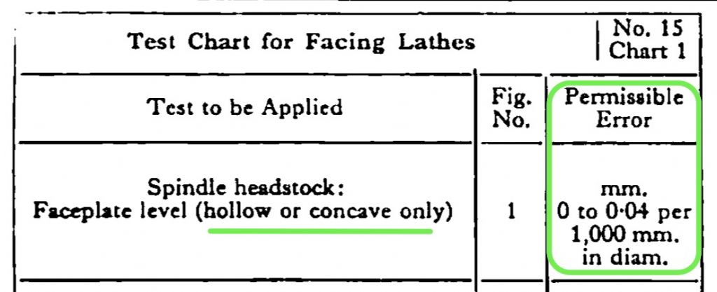
                          Various posts elsewhere on here have suggested that Myford deliberately set the machine to face very slightly concave.

                          On a used machine, half a thou sounds pretty good.

                          You may be in danger of straying into the territory where the repeatability and accuracy of the DTI comes into question.

                          Howard

                          #507497
                          Michael Gilligan
                          Participant
                            @michaelgilligan61133
                            Posted by Dr_GMJN on 14/11/2020 16:51:30:

                            Michael – please don't be offended. […]

                            .

                            Not offended at all …

                            I was merely was surprised that it was of no interest to anyone [not just your good self]

                            … I was expecting to spark some useful discussion.

                            MichaelG.

                            #507499
                            Michael Gilligan
                            Participant
                              @michaelgilligan61133
                              Posted by Howard Lewis on 14/11/2020 17:09:53:

                              Various posts elsewhere on here have suggested that Myford deliberately set the machine to face very slightly concave.

                              .

                              It’s widely accepted best-practice, Howard

                              … Hence my reference to Dr Schelsinger

                              MichaelG.

                              #507503
                              Dr_GMJN
                              Participant
                                @dr_gmjn
                                Posted by Howard Lewis on 14/11/2020 17:09:53:

                                Various posts elsewhere on here have suggested that Myford deliberately set the machine to face very slightly concave.

                                On a used machine, half a thou sounds pretty good.

                                You may be in danger of straying into the territory where the repeatability and accuracy of the DTI comes into question.

                                Howard


                                Howard,

                                Honestly I'm not fussed about the 0.0005" convex. The stuff I'm doing is over a much smaller distance than a faceplate radius; my 10V would not suddenly stop running if it ever found out it had been machined on such a horribly wobbly machine.

                                It's fine, I just thought for this, where it's pretty critical, I might as well use the mill. And I know it might be even less accurate than the lathe, but lets not get into that.


                                ETA it was a finger gauge, each divsion was 0.0005"

                                Edited By Dr_GMJN on 14/11/2020 17:37:23

                                #507509
                                Michael Gilligan
                                Participant
                                  @michaelgilligan61133

                                  Too late to append this to my previous post:

                                  1369c5fb-296e-47a3-b987-ab9ed11749b9.jpeg

                                  .

                                  N.B. __ Some emphasis required when we mention very slightly 

                                  MichaelG.

                                  Edited By Michael Gilligan on 14/11/2020 17:56:05

                                  #507525
                                  Les Jones 1
                                  Participant
                                    @lesjones1

                                    You could try my suggestion by making a washer out of some thin metal. The hole size would be the diameter of the outer edge of the three grub screw holes.

                                    Les.

                                    #507543
                                    Rod Renshaw
                                    Participant
                                      @rodrenshaw28584

                                      The blueing tests on each surface ( block and topslide) seem to show fairly flat surfaces, yet the block still rotates under load.

                                      Is it possible the resurfacing of the topslide has been done before so that the thickness of the casting is now such that when the clamp handle is tightened the surface of the topslide distorts, with the centre belling upwards, until the clamp is tight (at the centre) but there is little clamping force towards the outside edges where it is really needed to prevent rotation?

                                      Not sure how to measure this possible effect, but experiments with a large washer as Les suggests above might be useful to see if this is a possible cause of the remaining problem. A temporary washer could be cut with snips or scissors out of any available thin material.

                                      Thinking again about measuring the effect, one might mount a DTI to touch the top of the toolpost/ pivot bolt from above to measure vertical movement, and see if the reading changes as the clamp handle is tightened.

                                      Interesting experiment!

                                      Not sure about a remedy but just possible re-cutting the surface with a fly cutter might give a shallow hollow surface (hides under tin hat!) or make a more permanent washer from shim and stick it to one of the surfaces to avoid weakening the surface further.

                                      Rod

                                      #507552
                                      SillyOldDuffer
                                      Moderator
                                        @sillyoldduffer
                                        Posted by Dr_GMJN on 14/11/2020 17:23:33:

                                        Posted by Howard Lewis on 14/11/2020 17:09:53:

                                        Honestly I'm not fussed about the 0.0005" convex. …

                                        That's worth investigating. Lathes are set up to cut slightly concave because it means faced work will always sit flat, which is important. If a lathe cuts even slightly concave the resulting face won't sit flat causing big trouble – rocking, stressed bolts, and inability to form seals etc. Although the error is small, it's doubled when two faces from the same lathe have to be mated. In comparison seriously concave cutting is OK.

                                        Not sure what would cause convexity. Bed twist maybe, or possibly the bed is worn near the chuck? Be excellent if it was due to the rounded tool-post allowing the cutter to turn slightly as it moves across the face, because that problem's already in hand.  (Apologies if that's someone else – past my bedtime!)

                                        Dave


                                        Edited By SillyOldDuffer on 14/11/2020 22:04:30

                                        #507553
                                        Dr_GMJN
                                        Participant
                                          @dr_gmjn

                                          Rod, I’ve no idea whether the rotation issue has been cured or not. I was just checking that the surfaces mated, using the blue, and got sidetracked by the inconsistency of the results.

                                          I only loaded the clamp such that I could rotate the block slightly in order to get an impression on the opposing faces.

                                          I suppose it could have been skimmed previously, but visually it looks like all the others I’ve seen online. There’s a fair chunk of metal under there.

                                          Anyway I’ll put it back together tomorrow and give it a go.

                                          #507554
                                          Hopper
                                          Participant
                                            @hopper
                                            Posted by Dr_GMJN on 14/11/2020 16:09:32:

                                            Completely different result.

                                            Am I doing something stupid here?

                                            Do I just go with the last result, because if it was severely out of flat, I'd never be able to get that result, and assume its somehow my technique for blueing that's at fault?

                                            Yes your blueing technique is not best practice.

                                            From the pics it is obvious you are not moving the block enough. You need to rotate it back and forth a quarter of a turn or so at least half a dozen times. This gives the blue a chance to transfer from one surface to the other on the high spots. Just sitting it there, or moving it a degree or two will not work as well and will give inconsistent readings as the job sits up on a layer of that goopy blue liquid/paste.

                                            When checking the block on the surface plate, blue up at least 8" square and move the block around in a figure 8 pattern four or five times.

                                            Be wary of using too much downward force on the block in the process. If you push through the layer of blue you will get metal to metal contact that appears as shiny metal and can be mistaken for a low spot instead of the extra-high spot it really is.

                                            Try to use less blue. Its hard to tell from pictures but I have found if you can see the blue clearly in a photo, you've got too much on there. The thinner you can spread that stuff, the more accurate the reading it gives you. It just means you have to look very carefully at the tested piece in just the right light to see where the blue has left its marks. This helps gives more consistent readings. Thick layers of blue squish around all over the place under pressure and give inconsistent readings.

                                            When reading the blue, look only at the piece that you did not put the blue on prior to assembly. It is the patches of blue that its high spots have picked up from the other fully blued surface that tell the story.

                                            Don't try to interpret anything from where the blue appears to be rubbed off the "master" part that received a full coat of blue prior to rubbing the two parts together. It will tell you lies.

                                            #507560
                                            Dr_GMJN
                                            Participant
                                              @dr_gmjn

                                              Don’t fully follow that Hopper, at least not for two surfaces of unknown flatness like in the image in your quote. imagine the two surfaces are potentially like Pringles, or wavy washers. Surely quarter of a turn could potentially hugely increase the high and low areas that slide into contact, and mask the true initial contact patches, and give the impression contact is over a much larger area.

                                              Not that I’ve ever done it, just seems logical to assume that a small angular movement will give a more realistic result on a part that’s not rotating relative to the other.

                                              #507567
                                              Hopper
                                              Participant
                                                @hopper

                                                Just sharing my personal experience over countless hundreds of hours of using bearing blue at work and at home on jobs ranging from those as big as a house down to the exact thing you are doing.

                                                I never studied on the topic using logic and intellect to develop any kind of underlying theory so couldn't comment on that.

                                                I only know what has worked for me over the years and what hasn't.

                                                #507592
                                                Dr_GMJN
                                                Participant
                                                  @dr_gmjn
                                                  Posted by Hopper on 15/11/2020 01:30:35:

                                                  Just sharing my personal experience over countless hundreds of hours of using bearing blue at work and at home on jobs ranging from those as big as a house down to the exact thing you are doing.

                                                  I never studied on the topic using logic and intellect to develop any kind of underlying theory so couldn't comment on that.

                                                  I only know what has worked for me over the years and what hasn't.

                                                  Fair enough. As I said, I’ve never actually done it, it’s just the first scenario that came to mind as I read it: the more you move two imperfect surfaces, the more chance there is of high and low spots touching occasionally. Maybe as one surface contacts, the initial contact blueing gets wiped off – I don’t know.

                                                  Thanks.

                                                  #507593
                                                  Ramon Wilson
                                                  Participant
                                                    @ramonwilson3

                                                    Okay – lets step back from this for a minute. You need to go back to go forwards

                                                    Put the blue to one side (you are using too much as said) and clean the surfaces.

                                                    I see someone has mentioned this before – ditch that spring washer under the spacer – if neccesary make a washer of equivalent thickness preferably larger in diameter but with clearance milled in to clear around the cams – That should put your lever in more or less the same position. Better still, ditch the lever too and replace with a nut – standard issue on my S7 – 7/16 BSF if I recall correctly, and use a spanner, been working fine for me since 1970.

                                                    Re assemble but with the thin piece of paper as suggested – at first. Clamp up and see if you have any improvement. If so remove the paper and try again. If you can find any kind of slippage then the paper is telling you something – you can investigate further with seeking perfect flatness or continue with the paper – that will only need occasional changing if so.

                                                    Like Hopper and no doubt many others on here trying to help we have a lot of time put in over the years . In my opinion you are now looking for something not there – if you are clamping it with sufficient pressure what you have acheived is more than adequate – any form of 'give' in the system such as that washer will not provide a firm grip.

                                                    Ramon

                                                    T

                                                    #507594
                                                    John Haine
                                                    Participant
                                                      @johnhaine32865

                                                      Skimming back over this thread it seems to me that we don't necessarily know by how much the toolpost was moving or under what load. It looks like there is a good chance that the mating surfaces are reasonably flat.

                                                      My experience with the Dickson toolpost on my CNC-converted S7 is that it did move under load, especially when parting, by amounts that while quite small made it impossible to rely on calibrated tool offsets. Combined with the relative flimsiness of the Myford topslide and the fact that a topslide is redundant for CNC provided one has a means of referencing the Z axis to the end of the work, led me to make a fixed block to replace the topslide and to add a locating pin to the Dickson toolpost to positively locate it with a matching hole in the block. See my album here.

                                                      Since the OP's toolpost does have a dowel hole maybe the simple answer is to drill and ream a matching hole in the topslide, spotting through from the toolpost whilst accurately squared to the chuck surface. If the dowel is made removable it could still be taken out if it's necessary to slightly rotate the toolpost angle (though I have never found a need to do that).

                                                    Viewing 25 posts - 76 through 100 (of 119 total)
                                                    • Please log in to reply to this topic. Registering is free and easy using the links on the menu at the top of this page.

                                                    Advert

                                                    Latest Replies

                                                    Viewing 25 topics - 1 through 25 (of 25 total)
                                                    Viewing 25 topics - 1 through 25 (of 25 total)

                                                    View full reply list.

                                                    Advert

                                                    Newsletter Sign-up