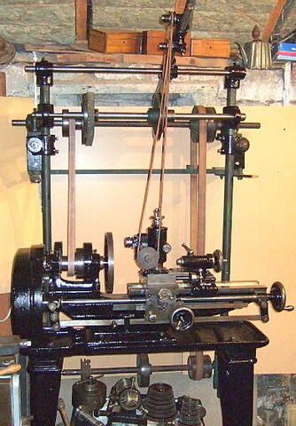
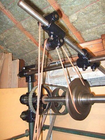
mini overhead drive – opinions please
mini overhead drive – opinions please
- This topic has 48 replies, 14 voices, and was last updated 12 March 2019 at 08:57 by
 Hopper.


- Please log in to reply to this topic. Registering is free and easy using the links on the menu at the top of this page.
Latest Replies
-
- Topic
- Voices
- Last Post
-
-
QCTP for chester lathe
Started by:
Chris12
in: Beginners questions
- 3
-
12 August 2025 at 21:48
Stuart Smith 5
-
Backplate
Started by:
Steve355
in: General Questions
- 5
-
12 August 2025 at 21:45
Howard Lewis
-
How does this power pack work?
Started by:
ell81
in: Beginners questions
- 4
-
12 August 2025 at 21:17
Chris Gunn
-
Cheap DRO
Started by:
Steve355
in: General Questions
- 9
-
12 August 2025 at 21:04
Wink Hackman
-
Things you’d forgotten you had – Volstro Head
Started by:
Peter Neill 1
in: Workshop Tools and Tooling
- 5
-
12 August 2025 at 21:03
Pete
-
smokeless cutting oil
1
2
Started by:
Chris12
in: General Questions
- 16
-
12 August 2025 at 21:02
Chris12
-
What are these?
Started by:
ell81
in: Beginners questions
- 5
-
12 August 2025 at 20:04
old mart
-
Stuart Restoration
1
2
Started by:
Richard Simpson
in: Stationary engines
- 19
-
12 August 2025 at 17:29
Colin Bishop
-
What Did You Do Today 2025
1
2
…
8
9
Started by:
JasonB
in: The Tea Room
- 35
-
12 August 2025 at 17:16
John Hinkley
-
Maxitrak Atkinson Lorry
Started by:
Richard Simpson
in: Miscellaneous models
- 2
-
12 August 2025 at 16:16
Richard Simpson
-
Hex Wrench
Started by:
Vic
in: Workshop Tools and Tooling
- 13
-
12 August 2025 at 15:08
Pete
-
Thermal imaging
Started by:
John MC
in: The Tea Room
- 5
-
12 August 2025 at 15:07
Robert Atkinson 2
-
Who’s to be trusted ?
1
2
Started by:
Michael Gilligan
in: Electronics in the Workshop
- 16
-
12 August 2025 at 13:49
Michael Gilligan
-
How to annotate a group photo
Started by:
Greensands
in: The Tea Room
- 9
-
12 August 2025 at 13:20
blowlamp
-
EW Stringer Lathe Spindle Thread
Started by:
James A
in: Workshop Tools and Tooling
- 8
-
12 August 2025 at 12:57
BB12
-
TurboCAD Snaps and Dimensioning?
1
2
Started by:
Nigel Graham 2
in: CAD – Technical drawing & design
- 9
-
12 August 2025 at 08:55
Zephyrin
-
Rotary table Chuck mounting.
Started by:
John Gray 7
in: General Questions
- 9
-
11 August 2025 at 18:43
old mart
-
Mounting chuck directly to rotary table.
Started by:
old mart
in: Hints And Tips for model engineers
- 5
-
11 August 2025 at 18:14
old mart
-
Mini selfcentering stady rest
Started by:
dk0
in: Workshop Tools and Tooling
- 8
-
11 August 2025 at 16:49
dk0
-
Where to buy Model Steam Engines
Started by:
David Deaville
in: General Questions
- 5
-
11 August 2025 at 14:49
Richard Simpson
-
External Thread Cutting
Started by:
peak4
in: The Tea Room
- 1
-
11 August 2025 at 13:49
peak4
-
Odd RAF Specialist Tool?
Started by:
Martin King 2
in: Help and Assistance! (Offered or Wanted)
- 13
-
11 August 2025 at 11:24
Robert Atkinson 2
-
Whats app
Started by:
duncan webster 1
in: The Tea Room
- 5
-
11 August 2025 at 09:31
Adrian R2
-
New Compressor
Started by:
Andy Brocklehurst
in: General Questions
- 14
-
11 August 2025 at 09:23
noel shelley
-
(help) hobymat md65 lathe z1 and z2 gears
Started by:
johnnyboy11
in: Workshop Tools and Tooling
- 5
-
10 August 2025 at 21:00
Bazyle
-
QCTP for chester lathe


