Lister Drawings

Advert

Lister Drawings

Home Forums General Questions Lister Drawings

Viewing 25 posts - 26 through 50 (of 80 total)
  • Author
    Posts
  • #116096
    HobbyNut
    Participant
      @hobbynut

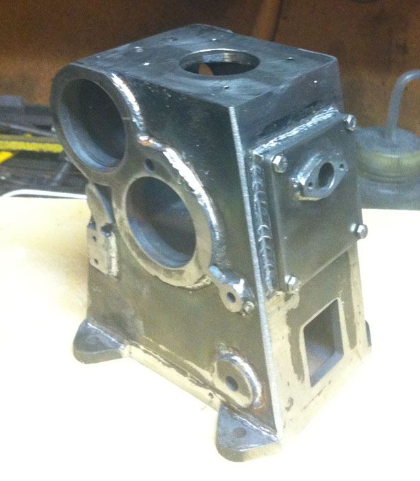
      So I have figured out the drawings, with JasonB and Georges help. The case I started on was incorrect, so I redid it with new sides and cover end.new case all ground.jpg

      Advert
      #116098
      Sub Mandrel
      Participant
        @submandrel

        How did you manage that in less than 25 hours, even with 'machine assistance'!

        Neil

        #116116
        HobbyNut
        Participant
          @hobbynut
          Posted by Stub Mandrel on 04/04/2013 16:08:13:

          How did you manage that in less than 25 hours, even with 'machine assistance'!

          Neil

          Neil, I cut the parts at work, took about 45 mins, went home had supper, went to garage about 6.30pm, took Dremel and cutoff wheel to old assembly, cut all tacks, cleaned up parts, tacked new parts together, welded them, took hot assembly to milling machine, removed vise, clamped down fabrication, took cleanup off base, flipped the case and cleaned up .75mm off top, flipped it sideways and propped it up to face off cover flange, took it back to welding shop and ground it down a bit, took the Dynabraid and did more cleanup, put a carbide bullnose x 1/8 dia. bit in the Dremel and dressed the welds a bit, drilled and tapped the holes for the cover, fitted the cover. Shut down the workshop(shed) and went into house had a shower and head hit the pillow at 11.00pm.

          crook

          #117644
          HobbyNut
          Participant
            @hobbynut

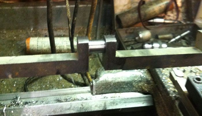
            A couple of parts in progress, the crank and the conrod.crank.jpgcon rod step 1.jpg

            #118355
            HobbyNut
            Participant
              @hobbynut

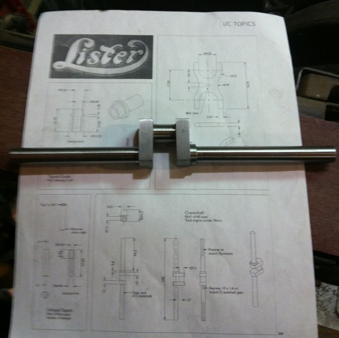
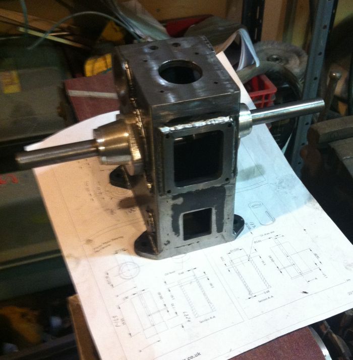
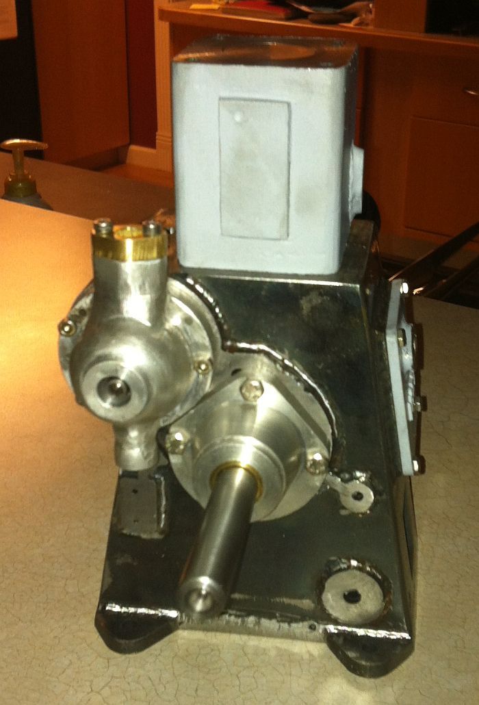
              Just an update on my progress on this. I have now got the crank and main bearings trial fitted.bearing housing.jpgcrankshaft.jpgcrank installed.jpg

              #120050
              HobbyNut
              Participant
                @hobbynut

                Still building away here..Have not found any more missing, or non determinable dimensions.

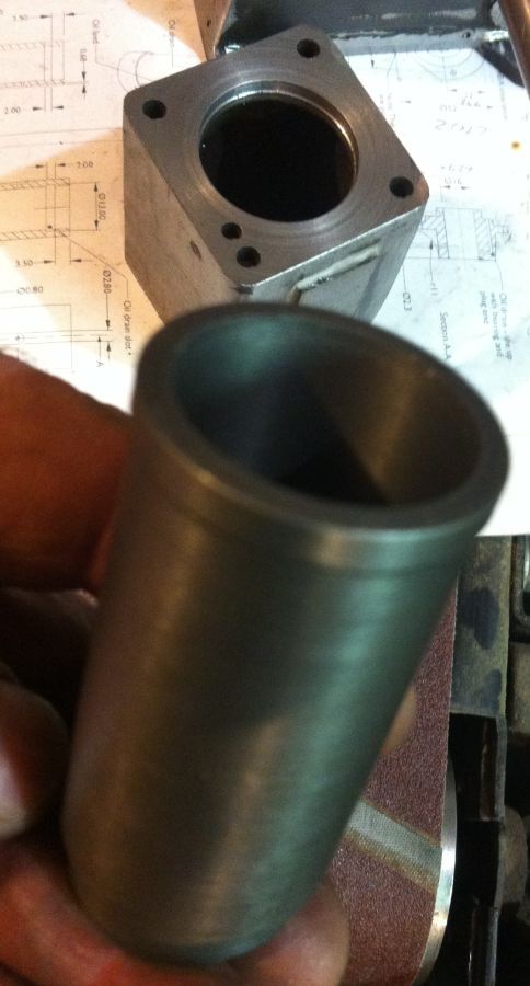
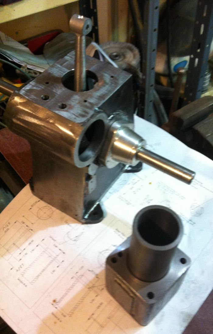
                cyl liner.jpgparts.jpgall parts so far.jpg

                #120467
                HobbyNut
                Participant
                  @hobbynut

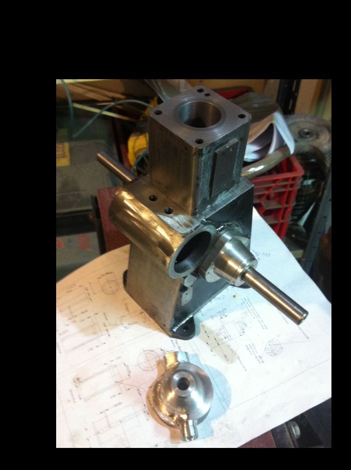
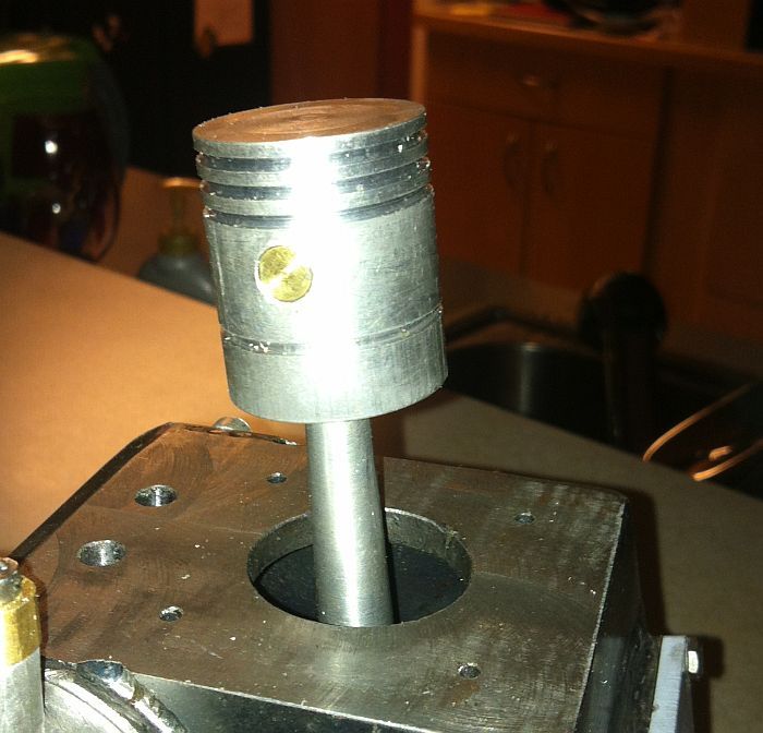
                  piston.jpglatest assy.jpggovernor housing.jpg

                  Some pics of my latest endeavors on the Lister.

                  #120762
                  Jeff Dayman
                  Participant
                    @jeffdayman43397

                    Regarding governor housing and oil pump drawings in ME4453 I have some questions and issues.

                    -“oil pump assembled” drawing across pages 500/501 has a note “spring fits here” on section a-a and in the oil pump body drawing’s section a-a there is a note “seat for o-ring and washer”. In my opinion there should be a spring, washer and o-ring shown in the assembly drawing so it is clear what configuration is intended. A note on washer and o-ring sies would also be useful. My impression from info provided is that the spring pushes upward on the part 4 spring cap, returning it and the part 5 piston after the stroke, and the spring also pushes down on the noted washer which rests on the o-ring which seals the piston shaft. If this is the intent, it is a poor o-ring design, because the ‘squeeze’ of the o-ring to piston fit will be higher when the spring is compressed. This will cause rapid o-ring wear. A better design would use a counterbore in the pump body designed for optimal groove dimensions for the o-ring to make a diametral seal (controlled by seat counterbore dia and piston dia only, not the counterbore height or washer compression). This would give a constant and controlled o-ring compression. The washer would just fit the piston and the pump 7mm ID. The washer would sit on step in the body above the o-ring and would not compress the o-ring. The washer would only support the spring. The “small oil groove” noted on the piston rod dia and should be stoned or filed so its’ edges are not sharp, or the o-ring may be cut by the groove during assembly. The end of the piston should be stoned or filed also, for the same reason.

                    -“oil pump assembled” drawing across pages 500/501 – placing a highly detailed cross section view across the page split is poor draughting and layout practice and could easily lead to misunderstandings of the drawing.


                    -spring length is noted as 7.2mm long – is this compressed length or free length of the spring? The space available for it on the assy looks like much more than 7.2 mm, but maybe I’m confused because the washer, spring and o-ring are not shown on the assembly drawing?

                    -“oil pump body” detail pg 501- 4.9 dimension on middle bottom view – is this the theoretical intersection dimension of the oil outlet boss and the main body turning of the pump? The angle of this fitting is given as “7t” rather than 7 degrees on the right bottom view. Was the “t” a typo or is it a “printer’s cross” to reference a later note?

                    Centre dimension of side bosses shown on different views from the dimension from the end, and this is in a different view than the dimension from pump axis. OD and ID dimensions of the bosses are at 90 degrees to each other in different locations on the view. Boss heights and position relative to central bore are missing from top view. Central bores 4 dia and 7 dia are dimensioned both in top view and section a-a. Note for 3/32 ball in pump body top view is confusing as it is noted in the assembly drawing already and is not part of the pump body fabrication shown in the pump body detail. Very poor draughting.

                    -“governor body” drawings pages 498-499 – The angled view at top right of page 499 (which is a duplicate of the bottom left view page 498) contains 3 notes that could easily have been included on the bottom left angled view on page 498. This would free up room for a scrap section showing full details of the recess called out in the 2 notes shown. In the bottom left view on page 499 a 20 mm dimension is given from the recess to the governor link boss face, but no dimension to either recess or boss face from centre is provided. No dimension is provided from centre to the outside face of the governor link boss either. No dimensions for the cam bearing inside face, main machined flange ID,OD or depth, dowel holes, bolt holes or flange step are provided. Very poor draughting.

                    -“backplate” detail page 500 – It is noted the sleeve is a separate part press fitted. It should be shown as such in the section, which by the way is missing “section a-a” callout. Very poor draughting.

                    Edited By Jeff Dayman on 27/05/2013 15:30:37

                    #121524
                    HobbyNut
                    Participant
                      @hobbynut

                      Jeff, the drawings are definitely confusing.

                      I am redrawing and fitting as I go now, as it seems to be the only way. I find it very difficult to figure out how the 2 pumps go together, as there is not an assembled cross section, or exploded assembly drawing of either.

                      I am concentrating on getting the basic, crank,cam, piston to all work together then hopefully the head details will turn up in the mag.

                      There is no detail of how the oil gets to the main bearings, or am I missing it.

                      #121908
                      Jeff Dayman
                      Participant
                        @jeffdayman43397

                        "HobbyNut" – Despite the poor drawings you are making great progress on your engine. It looks very good. Well done!

                        I just had a look at the injector pump drawings fopr the Lister in a recent ME and they are as bad or worse than the oil pump drawings.

                        I also do not have a good idea what the oiling plan for the main bearings is from the drawings so far. It would have been a good idea to include some detail on this important system rather than wasting space publishing mutliple crankcase views with uneeded dimensions and views (with many important dimensions missing, like crankshaft centre to bottom face dim) early in the series.

                        Unfortunately in the past editors of ME have vigorously defended the illustrator in Greece who transcribes drawings from contributors' sketches or drawings. I can't believe the contributors' own drawings are this bad and as poorly laid out as the ones shown in ME. The illustrator himself has said he is not a trained draughtsman. Not a shame in itself, but I would think having been called up on it numerous times in this forum he would take a course, or at least read a text on basic draughting, maybe!

                        Sorry to be so critical but it is frustrating to see, series after series.

                        Anyway good luck as you carry on with your Lister. JD

                        #121910
                        Sub Mandrel
                        Participant
                          @submandrel

                          Diane and "the illustrator in Greece" have found errors in my drawings!

                          Neil

                          #121925
                          Jeff Dayman
                          Participant
                            @jeffdayman43397

                            Neil-you have a private message. JD

                            #121926
                            Diane Carney
                            Moderator
                              @dianecarney30678

                              The Illustrator copies the author's drawings and the editor checks the illustrator's drawings against the author's original drawings. Only extremely rarely does an error end up in print that was the creation of the illustrator and in such an event it will be bacause the editor has not picked up the illustrator's error. If you regard something the author has drawn as erroneous, that's a different matter.

                              The illustrator does not add anything to or take anything from the author's original. Jeff, when you say:
                              'I can't believe the contributors' own drawings are this bad and as poorly laid out as the ones shown in M.E.' you are doing both a disservice. The illustrator's drawings are very precise copies of the original drawings. Call this vigorous defence if you like. It is simply fact.

                              Diane

                              #121938
                              Jeff Dayman
                              Participant
                                @jeffdayman43397

                                Hi Diane,

                                With respect, did you read my comments and "HobbyNut"'s comments about the Lister drawings in particular? There ARE severe problems with them. As presented, a great deal of insight and guesswork will be required to use them to make a model. "HobbyNut " deserves a lot of credit to have gotten this far.

                                Don't be surprised if you get multiple letters about the injector pump drawings on this model. There are major problems with those drawings and clarification will likely be required.

                                Best regards JD

                                #121948
                                Diane Carney
                                Moderator
                                  @dianecarney30678

                                  Yes, Jeff, I did read your comments.
                                  In a nutshell, again, if there are problems with the drawings, they are not created by the illustrator. I can not put it more succinctly.

                                  You describe the drawings as 'bad and poorly laid out'.
                                  Can I suggest you contact George Punter directly in order to clarify any problems? Having met him I found him a very pleasant, highly intelligent and very approachable gentleman. The work he has produced over many years is quite remarkable both in terms of quantity and quality.
                                  George has contributed to this forum previously.

                                  Diane

                                  #121951
                                  JasonB
                                  Moderator
                                    @jasonb

                                    I think it all comes down to what has been said in the past which is without a technical editor or draftsman who could look over the drawings and spot errors in the submitted work then Diane and the Illustrator can only be expected to reproduce what they are given.

                                    I can't see this changing much as I'm sure most subcsribers would not welcome the price hike that having another editor would add to the cover price.

                                    It is a pain though as there are some glaring errors that could have been picked up easily before the originals were sent to greece or even before submission.

                                    J

                                    #122209
                                    Ennech
                                    Participant
                                      @ennech

                                      Model Engineer the magazine publishes articles the purpose of which is to enable readers with a certain degree of skill to produce the models. I am sure that in English law it is the responsibility of the magazine to supply goods which are "fit for purpose", in this case the magazine article. The magazine cannot duck the issue by blaming either the contributor or their sub contractors.

                                      #122211
                                      Ian S C
                                      Participant
                                        @iansc

                                        I'm sure Diane could put someone in touch with Mr Punter, so thay could offer their services as a draftsman, and the draftsman and the engineer could work together. Ian S C

                                        #122887
                                        JasonB
                                        Moderator
                                          @jasonb

                                          Well the old saying that two heads are better than one may not be true in Issue4459 as we have two different drawings for the cylinder head.

                                          "cylinder head part one" has the O/A sizes dimensioned as 50×55 and thats what its drawn to yet the remaining five other drawings of the head show it as 50mm square.

                                          We also have two different 3D renderings and the recess in the head has two different shapes.

                                          One drawing says "5 holes 5mm dia" the next shows 4 at 5mm and one at 4mm with no indication of depth on the 4 or 5mm lone hole?

                                          I think in the future if ME takes on an almost drawing only subject like this then the drawings want a good looking over before comitting to publication as you don't have th eoption to say "its in the text"


                                          J

                                          Edited By JasonB on 22/06/2013 10:41:34

                                          Edited By JasonB on 22/06/2013 10:43:03

                                          #122897
                                          Sub Mandrel
                                          Participant
                                            @submandrel

                                            Why do I have the sinking feeling that in future issues of ME will have 'for illustrative purposes only' written on drawings and 'this is a fictional account, any resemblance to models living or dead is purely coincidental' on the constructional series?

                                            Neil

                                            #122901
                                            Stewart Hart
                                            Participant
                                              @stewarthart90345

                                              Error 1:- cylinder head part one" has the O/A sizes dimensioned as 50×55 and thats what its drawn to yet the remaining five other drawings of the head show it as 50mm square.

                                              Error 2:-One drawing says "5 holes 5mm dia" the next shows 4 at 5mm and one at 4mm with no indication of depth on the 4 or 5mm lone hole?

                                              Well I guess these bollocks can be put down to me I did check them out but missed them:- but in my defence the first drawing is of the casting so you will end up with whatever the casting comes out as.

                                              As for the four/five holes on the basic cylinder head drawing, there are five holes the four in the corner are obviously for the cylinder head bolts, I’ve no idea what the fifth is for but it is shown on the next drawing down as being 4mm diameter I missed that.

                                              Error3:- We also have two different 3D renderings and the recess in the head has two different shapes.

                                              I can’t spot any major differences Jason there are a view minor differences that are of no consequence or am i missing something important.

                                              Stew

                                              > >

                                              > >

                                              #122902
                                              JasonB
                                              Moderator
                                                @jasonb

                                                If you look at the 3D of the head in "Part1" its clearly drawn 55mm and the head holes are not in the corner, different flange shape, lines shown on the hole above flange on one and not the other

                                                Also on the same drawing the Top View shows the injector hole as 7, other drawings have it 7.2mm and the view from the flange end has a completely different flange shape to the one in teh basic dimension drawing.

                                                There are also 6 other holes in the head that have no size or position shown and a further two that should be there but are not shown atall

                                                Also very bad practice to dimension items from opposite sides of a "as cast" part if that is the case. Better to use one side or a central line as a datum

                                                Edited By JasonB on 22/06/2013 15:31:49

                                                #122906
                                                JasonB
                                                Moderator
                                                  @jasonb

                                                  Neil, I have a different theory. Mytimemedia are slowly combining their other titles into one magazine and the drawings in ME will soon feature in their other publication "Total Puzzels" as part of the spot the difference competitionsmile p I always liked those as I am no good on crosswords.

                                                  #122907
                                                  Stewart Hart
                                                  Participant
                                                    @stewarthart90345

                                                    Jason

                                                    The best way to view these drawings are as a sequence of machining operations, yes there are differences but the differences will iron out as you make the part and yes despite peoples best efforts there will be errors, but you must remember that this is for a model the drawings are not a contractual document as you get in industry, and they are done by hobbyist for hobbyist, and part of the fun/challenge is sorting out problems.

                                                    Error 4:-Also on the same drawing the Top View shows the injector hole as 7, other drawings have it 7.2mm and the view from the flange end has a completely different flange shape to the one in teh basic dimension drawing.

                                                    I read this as 7.2mm being the finished size the 7mm is the as cast size also as the part is machined it will look different>>

                                                    Error 5:-There are also 6 other holes in the head that have no size or position shown

                                                    Put them where they belong it something a builder can work out for himself it’s all part of the fun

                                                    Error 6:- Also very bad practice to dimension items from opposite sides of a "as cast" part if that is the case. Better to use one side or a central line as datum

                                                    As I said it’s a model for hobby model makers just because it bad practice for industry doesn’t mean it can’t be done for a model.

                                                    Stew

                                                    #122910
                                                    JasonB
                                                    Moderator
                                                      @jasonb

                                                      Stew do you honestly think any holes would be cored out in this head let alone a blind one at 7mm dia for a 7.2mm finish?

                                                      Also George said "No allowance has been made on the drawings for Machining or shrinkage"

                                                      J

                                                      EDIT, looks like the head was acutally cut from solid CI as its not listed in the items George said he cast so all those excuses about castings don't apply. I thought that may be the case as not many have the ability to melt CI at home


                                                      Edited By JasonB on 22/06/2013 16:19:08

                                                    Viewing 25 posts - 26 through 50 (of 80 total)
                                                    • Please log in to reply to this topic. Registering is free and easy using the links on the menu at the top of this page.

                                                    Advert

                                                    Latest Replies

                                                    Home Forums General Questions Topics

                                                    Viewing 25 topics - 1 through 25 (of 25 total)
                                                    Viewing 25 topics - 1 through 25 (of 25 total)

                                                    View full reply list.

                                                    Advert

                                                    Newsletter Sign-up