Indexable tool holders

Advert

Indexable tool holders

Home Forums Workshop Tools and Tooling Indexable tool holders

Viewing 25 posts - 26 through 50 (of 57 total)
  • Author
    Posts
  • #129442
    Ian P
    Participant
      @ianp

      Cabeng

      I've had the same thing done to my posts. Its the stoopid editor!

      It likes you to put a space before a closing bracket, OK its not the correct way of doing things but its just something we have to put up with on this forum.

      Onec again I must compliment you on your really good advice, You have an easy to read, style of writing and give good explanations and straightforward advice, thanks.

      Ian P

      Advert
      #129452
      Metalhacker
      Participant
        @metalhacker

        As this thread is about indexabletools, has anyone tried the HSS indexable tips from A R Warner in the US? Any good and do they have a UK distributor? It seems to me that foramatuer use these could be ideal, at least until one had made a decent T&C grinder.

        BW

        Andries

        #129574
        Anonymous

          Cabeng: I turn a lot of aluminium (mostly 6082), generally have few problems, and can get an excellent finish of about 1µm Ra. I have found that inserts specifically for aluminium seem to behave better. Here's a picture of the type of inserts I use:

          insert.jpg

          Note the polished finish, positive rake and sharp edge. In general facing is not a problem, but, as I mentioned, when turning the swarf normally comes off cleanly, albeit in a long ribbon. But sometimes, seemly at random, part way through a cut the swarf will 'birdsnest', and if it gets trapped between the tool and work it obviously scratches the finish. From the information on the box I seem be to pretty much in the recommended areas for doc, feedrate and speed, although at the lower end of the feedrates. For the tip shown, 0.8mm radius, the maximum feedrate is 0.5mm/rev. So may be I should try pushing it a bit and see what happens. surprise I very rarely get any obvious BUE with these tips. However, that is not to say that the swarf going doolally isn't caused by BUE if only temporary.

          On another matter I need to get my act together on setting tool heights. A lot of my turning is on largish diameters up to about 16", so I've been a bit cavalier about setting tool heights in the past. That's one of the little lightbulbs your posts have switched on; I need to look at height setting more carefully. I plan to buy an el cheapo digital height gauge, measure the centre height, and then make a cylindrical square of that height. I can then use the square to set a 'zero' on the height gauge and use the height gauge as a comparator on the insert. That way I'm not relying on the absolute accuracy of the cheapo height gauge. I've got an Etalon height gauge that I can use to make the initial measurement. I need to buy some 1.5" silver steel to make a hob for the worm gear for my traction engine steering, so I can use some of that to make the cylindrical square, and harden it.

          Regards,

          Andrew

          #129581
          JasonB
          Moderator
            @jasonb

            Watch the el cheapo digital ones, Someone bought me one from one of the regular advertisers here, it rocked on the base, the scribe pointed upwards and its the opposite hand to most height gauges which makes it hard to us eif right handed.

            I also use the same type of tip for Aluminium but with a much smaller 0.2 corner, works very well on bronze as well.

            #129604
            Russell Eberhardt
            Participant
              @russelleberhardt48058

              Personally, I've tried some of these height setting gadgets and find the easiest way is to set the tool height by eye against the tailstock centre and then take a trial facing cut across some scrap and make fine adjustments to eliminate any central pip.

              Russell.

              #129625
              Anonymous
                Posted by Russell Eberhardt on 14/09/2013 09:50:41:

                Personally, I've tried some of these height setting gadgets and find the easiest way is to set the tool height by eye against the tailstock centre and then take a trial facing cut across some scrap and make fine adjustments to eliminate any central pip.

                That's basically what I've been doing, except that I find that the pip breaks off at some point before one is exactly on centre height. For larger diameters the method is fine, but it is certainly not going to let me achieve the accuracies quoted by Cabeng.

                Jason: Thanks for the heads up; fortunately I'm left handed. smiley I've been looking at two height gauges; a 4" one from Machine-DRO, and a 6" one from Arc. My lathe swings more than 8" over the cross slide, so if I bought the 4" one I'd have to hack it about anyway. I may well have to modify the 6" one as well, but time will tell. The purpose of making a cylindrical square is to allow the height gauge to be used a comparator, rather than an absolute measuring gauge.

                Regards,

                Andrew

                PS: Forgot to add, I've also got the aluminium specific inserts in 0.4mm and 0.2mm radius. I try and rough with the 0.8mm radius and use the smaller radii inserts for finishing, if I need a sharpish internal corner.

                Edited By Andrew Johnston on 14/09/2013 11:11:48

                #129629
                JasonB
                Moderator
                  @jasonb

                  I'll just say you may be better off with the 4" wink 2

                  #129639
                  Anonymous

                    Looks like it'll be the 4" then, and I'll throw the base away and make a new one – Andrew

                    #129660
                    Bruce Voelkerding
                    Participant
                      @brucevoelkerding91659

                      Perhaps Cabeng could discuss more re tip geometry. It seems many users are not quite aware of the various top rake angles available with carbide inserts. I designed lathes for 12 years and I know the top rake angle was carefull selected for each customer runoff (to the likes of Caterpillar, John Deere, Ford, New Departure,etc). Most steel and iron jobs were run with negative rake insetrs due to it being a more robust insert. Another concern was the BUE. Another big concern was life of the insert.

                      I do not have first hand experience as I still use hand-ground HSS tools in my hobbyshop.

                      Bruce

                      #129662
                      Howard Lewis
                      Participant
                        @howardlewis46836

                        Some VERY informative posts, worthyn of being seen by the world at large, and kept!.

                        Setting the tool to centre heightis, in my view, very important.

                        If you don't all the clearance and rake angles go to pot.

                        Mostly, I use replaceable tips, and have a holder to use the unused corners.

                        HSS for chamfering, and mostly for parting off.

                        Being as careless as I am, there are plenty of damaged tips available for roughing work!

                        And the posts have explained, why, possibly some of my tips don't last very long.

                        My tools are set to simple centre height gauge, (invented by someone else) by adjusting until the tip corner just touches the underside of the blade.

                        The gauge is just three pieces of metal and one grubscrew. (Four and two grubscrews if you use it to set tools in a rear toolpost).

                        The gauge takes very little time and effort to make and saves time and tools, and improves finishes.

                        (On this subject, using a replaceable tip at low speed, on steel, with hand applied neat cutting oil, a really good finish results).

                        You can set a tool to centre height by trial and error, and then set the gauge to the tool, and use that setting for all subsequent tools.

                        If anyone wants to know the complicated /pedantic way that I set the height of the blade on the gauge, I can go into detail. But it does give the exact centre height for a particular lathe, despite any eccentricities.

                        Howard

                        #129790
                        Anonymous

                          After cogitating about buying a height gauge I've decided against it. The 4" one I was looking at didn't have very good resolution, as it was intended for woodworking. Also, the manufacturers' datasheet was confused about resolution and accuracy. If they can't get that right it doesn't give you warm and fuzzies about the product. In due course I'll make myself a simple mechanical height gauge to set tool heights. At least I'll save on batteries.

                          This afternoon I did some turning experiments with a bar of aluminium (6082) and the 0.8mm and 0.4mm radius inserts. The bar was 2" diameter and was running at 800rpm, so about 400sfpm. I started with the 0.8mm radius insert, a doc of 50 thou and a feedrate of 12 thou/rev, higher than I'd normally use. The swarf came off to the left as a nice tight spiral. Increasing the doc to 0.1" caused a bit of a birdsnest. Increasing doc again to 0.2" curled the swarf to the left, but it still got tangled up. Reducing feedrate to 4 thou/rev caused a birdsnest.

                          With the 0.4mm radius insert a doc of 50 thou and 4 thou/rev caused a birdsnest. A doc of 5 thou and feedrate of 2 thou/rev had the swarf coming off in thin spirals, a bit messy, but the swarf was too fine to affect the finish.

                          All in all very interesting. I guess I need to get organised and write the down feeds/speeds and rpm that work so that I can refer back in the future, rather than 'winging' it. As a general point I could probably do to increase feedrates when roughing, and possibly decrease when finishing. I didn't pay that much attention, but I got the impression that the tool was not cutting when returning the saddle. That could make it easier to get parts on size. Ideally if I put on a doc of say 10 thou I expect the part to be 20 thou smaller. But life isn't always like that!

                          I've dug out my copy of 'Modern Metal Cutting' for re-read.

                          Regards,

                          Andrew

                          #129916
                          Cabeng
                          Participant
                            @cabeng

                            After returning late from a long weekend away, I did a reply to postings that had come in during my absence, only to have this bloody system loose it! Too late to re-do it now at 02:50 hrs, I'll get back to you tomorrow. Or later today!

                            #129962
                            Bazyle
                            Participant
                              @bazyle

                              Harking back to my days in education as a materials scientist I recall that metal is not cut but spit apart rather like a wedge splitting a tree trunk. After the initial penetration the wedge tip does not contact the wood but forces it apart such that a split runs well ahead of the wdge itself.
                              A lathe tool causes a crack to form ahead of the tool and no metal is in contact with the actual tip. The point of the crack propogates at the speed of sound (in the metal) and creates shock wave (sonic boom) ahead of it which helps break the atomic bonds between the metal atoms and significantly reduces the energy required. If the tool advances at the speed of the crack it can be kept rolling but if slower the shock wave dissipates and the advantage is lost. Since the crack and shock wave cannot move faster than the speed of sound trying to speed up means enough stress has to be created to produce a new crack ahead of the primary crack in virgin metal. This substantially increases the energy requiement.

                              So for mass production the target is a specific speed through the metal.

                              #129973
                              Russell Eberhardt
                              Participant
                                @russelleberhardt48058
                                Posted by Bazyle on 17/09/2013 13:25:25:

                                The point of the crack propogates at the speed of sound (in the metal) and creates shock wave (sonic boom) ahead of it which helps break the atomic bonds between the metal atoms and significantly reduces the energy required.

                                Ah, is that why I sometimes get something like a sonic boom when I push things too hard? wink

                                Seriously though, what is the speed of sound in, say, mild steel?

                                Russell.

                                #129975
                                Anonymous
                                  Posted by Russell Eberhardt on 17/09/2013 14:23:07

                                  Seriously though, what is the speed of sound in, say, mild steel?

                                  It varies according to the type of steel and wave, but it's normally in the range 3-6000m/s. There's no way my lathe can get anywhere close to those speeds.

                                  Andrew

                                  #129984
                                  Sub Mandrel
                                  Participant
                                    @submandrel

                                    Sounds like an urban myth to me.

                                    Neil

                                    #130027
                                    Cabeng
                                    Participant
                                      @cabeng

                                      Andrew: having tried to get some information on your inserts, I am in some confusion, because I can’t get any consistent information! JTS have the –AK chipbreaker down as medium and heavy cuts:

                                      • Feed Rate = 0.004 – 0.020 ipr
                                      • Depth of Cut Range = 0.050 – 0.200 inch

                                      whilst their link to ‘Triumph Chip Control’ gives:

                                      • Feed Rate = 0.001 – 0.020 ipr
                                      • Depth of Cut Range = 0.004 – 0.200 inch

                                      which happens to be the same as on the Toolmex site, where it’s classed as ‘light to medium’! But according to the Korloy website at:

                                      **LINK**

                                      it sits nicely between the two (for both 0.4 and 0.8mm tip radius) at:

                                      • Feed Rate = 0.002 – 0.010 ipr
                                      • Depth of Cut Range = 0.012 – 0.140 inch

                                      Whilst on another page of the same Korloy data sheet it says max feed 0.020” and max depth 0.160”. So which is it? G.O.K.!

                                      Now I don’t have much experience of aluminium inserts, so I’m a bit out of my comfort zone here, but I think it’s a good guess to say that they will be designed to produce short curly or comma chips, so as to provide easy clearance from automatic machines. Long continuous spirals would not be popular as the machine would have to be stopped to rake it all out, and tangled stringy swarf would be as welcome as a f**t in a lift. Bearing that in mind, together with the Sandvik diagram of chip formation, your recent tests show that everything is going according to plan, and perhaps provides some clues as to why it’s the wrong plan!

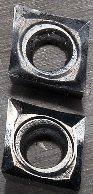
                                      You’ve been working at the left hand edge of the envelope shown on the first page of the Korloy data sheet, perhaps even a bit left of it – marginal conditions for long spirals, so that it only takes a bit of a hiccup at the tool tip to throw it further left and get into stringy mode. Perhaps just build up of aluminium on the surfaces across which the chips must travel, as in this photograph of the Sandvik tip I mentioned earlier – used tip at the top, unused at the bottom:

                                      alitips.jpg

                                      Moving rightwards on the diagram by increasing the feed might serve to get it away from marginal conditions, hence the good spirals at 0.012” feed. That, together with your doc of 0.010” puts the conditions more or less in the middle of the Korloy diagram, so I would have expected it to be forming non-continuous chips – so why is it not doing that?

                                      I don’t know the answer, but suspect a clue might lie on the left axis of Korloy’s diagram – cutting speed might be too low to smash the chips hard and fast enough against the breaker bits of the tip to actually break up the spiral. You’re down at 25% of the recommended cutting speed, so I’d have a go at higher cutting speed.

                                      Of course, if you’re happy with continuous spirals at doc 0.050” and feed 0.012”, then you’ve found your solution. But if not, here’s something else you can try to find, in a logical manner, what would suit you:

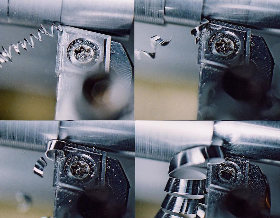
                                      Say you’re happy with doc 0.010” or steps thereof. Turn a bar down in 1” long steps with doc .010” for each step. Whilst doing this, try different feeds for each step until you find a satisfactory chip formation. Set this as your feed. Then turn the whole length parallel at that feed, so doc increases in 0.010” steps as you proceed along the bar. With a bit of luck you’ll hit gold. The following photographs show this process for a Sumitomo tip cutting steel at feed 0.004”:

                                      depth.jpg

                                      Top left – doc 0.005”

                                      Top right – doc 0.015”

                                      Bottom left – doc 0.025”

                                      Bottom right – doc 0.120” feed 0.002”

                                      These piccies also show exactly how the Sumitomo breaks the chips. In the first one the thin spiral is formed by the primary cutting edges, but the spiral runs away from the tip without further contact and remains as a spiral.

                                      For the second two, look at how the chip breaker grooves are working – the thicker spiral from the primary cutting edges first contacts the chipbeaker formations, which deflect it downwards so that the spiral now contacts the leading edge of the chip, where it gets broken into bits.

                                      In the last one, the same thing happens, but the spiral is now strong enough to resist fracture.

                                      #130028
                                      Cabeng
                                      Participant
                                        @cabeng

                                        Bruce:

                                        Perhaps Cabeng could discuss more re tip geometry. It seems many users are not quite aware of the various top rake angles available with carbide inserts.

                                        I'm not sure what you're after here, are you refering to positive and negative rake inserts, or rake angles for specific positive rake tips? Could you clarify please?

                                        #130029
                                        Cabeng
                                        Participant
                                          @cabeng

                                          Re. height gauges for setting tools accurately to centre height.

                                          I made a setting gauge for the S7B, which sufficed until I added the Connoisseur two years ago – which unfortunately has a different centre height to the S7B. I didn't fancy making another gauge, so I bought a 150mm Baty digital height gauge at Harrogate in 2011.

                                          Having determined the centre height of each machine from bed and topslide (sometimes one is more convenient to use than the other ) and stuck the numbers to the wall behind each machine, there's no need to make any other form of gauge.

                                          Has the advantage that as well as setting tools, I can actually do a quick measurement of the height of each tool as it gets fitted to the Dickson, as a check. Or use it to check the height if something isn't going to plan.

                                          Oh, and it can also be used as a height gauge!

                                          #130036
                                          MICHAEL WILLIAMS
                                          Participant
                                            @michaelwilliams41215

                                            http://aluminium.matter.org.uk/content/html/eng/default.asp?catid=147&pageid=2144416182

                                            There is a great deal of information about machining Aluminium on this site . There are many pages and external links to explore .

                                            MikeW

                                            #130050
                                            MICHAEL WILLIAMS
                                            Participant
                                              @michaelwilliams41215

                                              Just a note :

                                              When trying to solve machining problems for a particular metal it is often better to start research based on the metals rather than on the cutting tools .

                                              Most of the various metals industries have extensive machining data available specific to their metals group .

                                              For the common metals there are sites for industry wide organisations and for individual manufacturers .

                                              Some of the sites give links to research groups and archives where primary source information can be found .

                                              Altogether a vast store of information .

                                              MikeW

                                              #130180
                                              Sub Mandrel
                                              Participant
                                                @submandrel

                                                Hi Cabeng,

                                                Excellent series of pictures showing swarf formation!

                                                Neil

                                                #130295
                                                Anonymous

                                                  Hmmmm, looks like I might be making another U turn, and ending up where I started, by buying a height gauge to set tool heights. I might have to spend a bit more than I was intially thinking though.

                                                  I need to stand at the lathe and do some proper experiments with speeds, feeds and doc. I don't follow the comment that I'm at 25% of the recommended speed? Here's a picture of the back of the boxes of inserts I bought:

                                                  cutting data.jpg

                                                  At 400sfm I'm a bit below the recommended rate, but still comfortably within the specified range, unless I'm misinterpreting something?

                                                  Regards,

                                                  Andrew

                                                  #130303
                                                  Cabeng
                                                  Participant
                                                    @cabeng

                                                    Mmmm – the cutting speeds on the boxes are puzzling – have a look at the link I posted, which takes you to a Korloy data sheet for the tips. The cutting speeds thereon are 10 x what's on your boxes, up to 1500 m/min!

                                                    #130515
                                                    Anonymous

                                                      There's no way I can cut at anything like 1500m/min. When time permits I'll have a go at 1700rpm, just over double what I used before, but still not close to the recommendations.

                                                      Regards,

                                                      Andrew

                                                    Viewing 25 posts - 26 through 50 (of 57 total)
                                                    • Please log in to reply to this topic. Registering is free and easy using the links on the menu at the top of this page.

                                                    Advert

                                                    Latest Replies

                                                    Viewing 25 topics - 1 through 25 (of 25 total)
                                                    Viewing 25 topics - 1 through 25 (of 25 total)

                                                    View full reply list.

                                                    Advert

                                                    Newsletter Sign-up