Indexable tool holders

Advert

Indexable tool holders

Home Forums Workshop Tools and Tooling Indexable tool holders

Viewing 25 posts - 1 through 25 (of 57 total)
  • Author
    Posts
  • #17165
    Martin Walsh 1
    Participant
      @martinwalsh1
      Advert
      #129232
      Martin Walsh 1
      Participant
        @martinwalsh1

        Hi

        A while ago I received as a gift a set of 8mm mini turning tools

        thought I would try them out today.

        I tried to turn 1 inch dia free cutting mild steel and got a very poor surface finish

        I was running abt 700 rpm on my Super 7 fine feed 4 thou per rev

        the indexable tool holders where not cheapo ones but a good make

        what im I doing wrong

        #129237
        Thor 🇳🇴
        Participant
          @thor

          Hi Martin,

          Not easy to say without seeing your results. Carbide tools want high speed, have you tried increasing the speed? 700RPM for a 1in. diam. freecutting steel is approximately what you might use with a good HSS tool.

          Carbide tools also need a rigid setup. I use carbide for roughing and turning hard materials (castings), for finishing I use HSS.

          Thor

          #129250
          Clive Hartland
          Participant
            @clivehartland94829

            Hello Martin, Increase the spindle speed 150% and use a good depth of cut as carbide tooling will not cut a fine feed. The carbide tool shears and does not cut like HSS.

            Check that the edges of the tool are not chipped as that will give poor finish. The turnings may come off the job hot and blue and that is situation normal.

            Clive

            #129253
            Martin Walsh 1
            Participant
              @martinwalsh1

              Hi Thanks for the replies I will try a higher speed and coarser feed

              Should I use any cutting oil ?

              Best Wishes Martin

              #129267
              Cabeng
              Participant
                @cabeng

                Martin/Thor/Clive – I might end up regretting starting on this, but here goes anyway…..!

                The comments re speed and rigidity w.r.t use of carbides are commonly expressed, but they're not the whole story.

                Speed is easily dealt with – carbides will cut quite satisfactorily at low speeds. Very low speeds – if they wouldn't do that then they wouldn't be capable of parting off, facing off, or drilling.

                I suspect the idea that they need high speeds originates from manufacturers' recommendations that to improve finish one should increase the speed – someone has heard this in the past, and it's been handed down ever since.

                Well, the recommendation is correct, but it's being taken somewhat out of context. A common cause of poor finish is the formation of a built up edge (BUE) on the tool tip, caused by material from the workpiece becoming welded to the tip. The formation of BUE depends on the material being cut, the material of the tip, and the temperature at the interface between the two. The normal recommendation is to increase the cutting speed, which increases the temperature at the interface and takes it above the region where welding can take place.

                Industry isn't interested in going slower, so that recommendation would not be welcome! We, on the other hand, very often can't increase the speed sufficiently. So do the opposite, and slow down! The interface temperature drops BELOW the welding range, and good finish results.

                To further illustrate this effect, we've all seen it many times, albeit without realising what's happening. Imagine facing off a 4" disc – good finish at the outside where the speed and temperature are high, then it falls off part way across as the temperature enters the critical region and BUE forms, and comes back to good when the speed and temperature falls below the critical region. If you were to double the speed for another cut with identical depth of cut and feed, you would find that the 'poor' finish region now occurred at half the diameter.

                As far as the tendency to produce BUE goes, somewhat crudely and arbitrarily…

                Aluminium/HSS – AAAAGH!

                Steel/HSS – Not so bad

                Steel/Tungsten carbide – Better

                Steel/Titanium carbide – Good

                Steel Titanium nitride – Gooder. Sometimes.

                So the 'need for speed' is not intrinsically linked to the carbide itself, it's linked to the avoidance of BUE. The suggestions to increase speed will have an effect if BUE is the cause of the problem, as long as you increase it sufficiently to get out of the BUE region, and that depends on the actual tips you have. If you're comfortable with the S7 at top speed, go for it, but if you're not used to this, be aware that the carriage does tend to approach the chuck surprisingly quickly!

                Clive's suggestion re increasing depth of cut – yes, try that, as taking more metal off will increase the interface temperature and might help you get away from the BUE region. But as far as not liking fine feed is concerned… well, that depends on the tip. A new Sumitomo CCGT060602 in T1200A titanium carbide will take off less than a thou. at 0.002"/rev, but one designed for turning tyres on 12" scale loco wheels would need a bit more than that!

                You could also try going slower, of course, but not so low as to need back gear.

                But when trying different rpm, keep the depth of cut and feed the same, otherwise you'll be introducing additional variables into the mix, each of which will affect the interface temperature, and possibly the finish that results. Which would lead to confusion.

                Now the website says it was too long, so the bit about rigidity comes in the next posting!

                #129268
                Cabeng
                Participant
                  @cabeng

                  Turning to rigidity (and this is bound to rattle a few cages!) – if a machine/tooling/job setup is rigid enough for HSS, then it's rigid enough for carbides!

                  The need for rigidity depends upon the forces generated at the tool tip, which depend on the force needed to shear the material (referred to as the specific cutting force), the depth of cut, and the feed. For a given material, depth of cut and feed, it is INDEPENDANT OF THE TOOL MATERIAL. Taking ten thou. off steel at 0.004" per rev. will require the same force at the tool tip whether the tool is HSS or carbide.

                  In fact, in certain circumstances, the forces with a carbide tool will be LESS than those with an HSS tool. Say your Myford has a 1h.p. motor and you want to shift the steel as fast as possible, using the full 1h.p. (I'm neglecting power and gear train losses here) An oft-quoted and reasonable figure is 1 cu.in. of steel per minute per h.p., so you can do this in one cut at lowish speed using an HSS tool, resulting in a certain force at the tool tip, trying to deflect it downwards.

                  Alternatively, do it with carbide in 3 cuts at one third depth of cut and three times the rpm, still removing 1 cu.in. of steel in one minute (neglecting time to wind the carriage back, of course!), still using 1 h.p.

                  Now: Power = Torque x RPM

                  And: Torque = Force x Radius

                  Hence: Power = Force x Radius x RPM

                  And since the RPM is now three times greater than before, the force at the tool tip is only one third of that required to shift metal at the same rate as the HSS tool.

                  So, assuming that Martin and his machine can get good finish on FCMS with HSS, speed and rigidity are not the causes of his poor finish with the carbide tools. If his S7 is in good condition, then I know for sure that 700 rpm on 1" diameter FCMS is fast enough, and the machine is rigid enough, to give good results. We need to look elsewhere for the cause of his difficulties.

                  Some questions for Martin:

                  1) Is the machine (bearings, chuck, slides, everything) in good nick? If not, you need to fix it! Not for carbides, but for all cutting tool materials.

                  2) Do you get good results with HSS? If not, put away the carbides until you've sorted out things for HSS.

                  3) Are you an experienced user of your lathe, or still near the bottom of your learning curve? If the latter, see 2) above!

                  4) Do you know the exact details of the tips that are fitted to your tools? If so, please advise. If not, throw them away. Use of an inappropriate tip is, in my experience, the commonest cause of poor results for model engineers.

                  5) How do you set the tool to centre height?

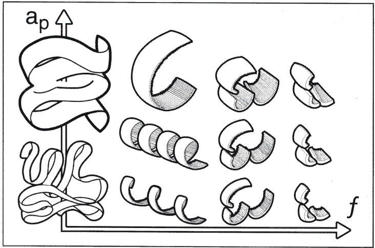
                  6) Can you describe the swarf? Not bothered about colour, it's the form that matters, it will give clues as to whether or not your tool is cutting within it's design envelope. Very short comma shaped chips, short spirals less than say 10mm long, longer spirals, continuous spirals, wirey flat strips with a tendency to wrap themselves around everything?

                  #129270
                  Cabeng
                  Participant
                    @cabeng

                    Martin:

                    Use of cutting oil. No, definitely not. Carbides need either a full flood of coolant, or nothing at all.

                    Dripping/brushing it on risks causing rapid temperature changes at the tip, which can lead to micro-cracking of the carbide and premature failure. Also the temperatures that can result when cutting without full flood can cause the coolant to dissociate into unknown chemicals – better not to risk that!

                    #129299
                    Martin Walsh 1
                    Participant
                      @martinwalsh1

                      Hello thanks for the info these are the answers

                      1 yes the machine is in good nick bearings slides etc

                      very well looked after

                      2 I get a mirror finish with HSS I grind all my hss blanks myself and use a diamond stone

                      to get a nice edge

                      3. Iam a experianced lathe operator been using lathes for nearly 40 years

                      as a hobby and for a living but have never used inserts have used wimet carbide tools

                      for cast Iron

                      4.Yes these are the tools in the set

                      1 turning and facing 90 degrees with 95 degrees approach Right Hand

                      2 same as above but Left hand

                      3 turning with 75 degrees approach right hand

                      4 same as above but left hand

                      5 I use a gauge with a spirit level

                      6 longer sprials

                      Best Wishes Martin

                      #129307
                      JasonB
                      Moderator
                        @jasonb

                        The fact they are in a set makes their quality questionable, all the name brand holders will not be in sets despite you saying they are a good make.

                        Can you say what make they are and what make and spec the inserts are. Photo swould be handy too.

                        J

                        #129313
                        Tony Pratt 1
                        Participant
                          @tonypratt1

                          As has been said already carbide will take a fine feed with no problem and also sets of carbide tools tend to not be of the best quality.

                          Tony

                          #129321
                          Cabeng
                          Participant
                            @cabeng

                            Hello Martin, thanks for the answers. 1 – 3 bode well for success with carbide tools.

                            Re 4 – I was hoping you would be able to provide the designation for the tips themselves, rather than the toolholder shapes. Something like Sumitomo CCGT060202-NSC T1200A. It's the -NSC bit that's of particular interest as this identifies the geometry of the chip breaker arrangements moulded into the tip, which in turn determine the ranges of feed and depth of cut for which the tip is suitable.

                            If you haven't got that information, your answer to 6 provides some guidance – you were cutting on the edge of the tip's envelope, or a little out of it. Have a look at this diagram, cribbed from a Sandvik publication, I think:

                            chipping.jpg

                            Tips are designed to produce comma shaped chips that are easily removed from the machine, and don't clog things up, and they would produce such chips if being used within their intended feed and depth ranges. Longer spirals suggests you're slightly outside the range for the tips you have. That's generally ok, a bit outside the envelope (in any direction) works fine in my experience, but as you are having some difficulties it would be better to have the tip cutting within it's range for now. So adjust feed and depth until you find a combination that gives comma chips.

                            Now to question 5 – mmm, no experience of those devices, but I can see a potential problem if either the lathe isn't perfectly level, and/or the chuck doesn't hold perfectly concentric – the tool tip could be off centre height. Carbides can be VERY touchy about centre height – get them even slightly above and you're in trouble as they'll be rubbing as well as cutting, which gives a poor finish. You might get away with ever-so-slightly high with a sharp HSS tool, but not with a carbide tip, as they don't have sharp edges. Sumitomo specify +0.000"/-0.0015". That's for a front mounted tool of course, reverse them for one in the rear tool post.

                            If you have a height gauge I would suggest that you use that for now, and aim for a thou or so below centre. But one thing NOT to do when setting a tool to height is to use the old trick of trapping a rule between the tool and the work – this kills carbide tips, stone cold dead. Micro-cracking again. Never let a tip contact stationary metal, they don't like up 'em, Mr Mainwaring, they don't like it up 'em.

                            #129334
                            Sub Mandrel
                            Participant
                              @submandrel

                              Pah! Call that swarf?

                              My record is over eight feet of tightly coiled stainless steel, that's real swarf.

                              Neil

                              <who won't mention that it was a somewhat shorter length of swarf that snaked into the control box and blew up the PCB on his mini lathe>.

                              #129347
                              Cabeng
                              Participant
                                @cabeng

                                Pah! Call that swarf?

                                My record is over eight feet of tightly coiled stainless steel, that's real swarf.

                                Neil

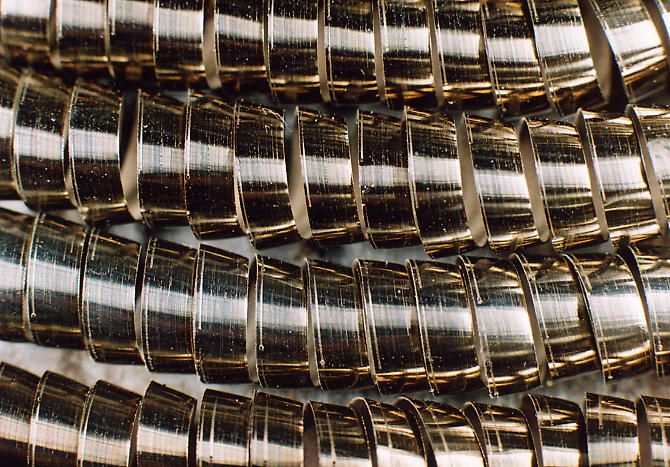
                                Something like this?….

                                6.7.jpg

                                Yes, that's swarf. Nasty stuff, gets into lots of places you wouldn't want it to get into ..!!! I'll stick to chips with everything!

                                Something I forgot to mention, another check for a carbide tip cutting correctly, as intended. Watch the formation of the chips (or swarf, if you haven't got it right!), and you should see the waste material being directed to the left of the tool, in the direction of the un-machined surface. If it's going the other way, right and towards the newly machined surface, then a) something is wrong, and b) it can cause poor finish if it contacts the newly-cut surface.

                                #129377
                                Anonymous

                                  Cabeng: Blimey, those are some of the best posts I've ever read regarding the use of insert tooling, not just on this forum, but anywhere.

                                  I tend to use insert tooling as a matter of course on my centre lathe, with HSS and gauge plate used for specials and form tools. Generally I can get a finish on the order of 1-2µm Ra, but it's not as consistent as I would like. Your posts have certainly illuminated a few lightbulbs for me. I wondered why the finish changed from state to state, and then back again when facing a large diameter. Plenty to think about. I think I need to pay more attention to what I'm doing, rather than 'winging' feeds and speeds, based on experience.

                                  Being a technical pedant I would point out that for consistency of units power (W) equals torque (Nm) times angular velocity (in radians/second), rather than rpm. smiley

                                  Now, a question on turning aluminium (6082) if you don't mind. I use Korloy CCGT-09T30x-AK inserts, specifically for aluminium. Generally the swarf exits stage left, which is good, and I get an excellent finish. But apparently at random the swarf can suddenly create a birdsnest, which gets trapped between the tool and work, giving a dull finish. Any advice?

                                  Regards,

                                  Andrew

                                  #129378
                                  Ian P
                                  Participant
                                    @ianp

                                    Totally agree with Andrew J as what he wrote is almost exactly what I would have said. His turning experiences are exactly what I see too.

                                    Cabeng has put on paper a full treatise of the why's and wherefore's of tipped tooling. Its sensible, balanced, and worthy of publishing to a wider audience. It might silence some of people that slag off carbide and say HSS is all the model engineer should use.

                                    I know that some of the information he passed on is freely available in manufacturers catalogues and data sheets, but often only after you've registered and downloaded massive PDFs do you then discover you have to trawl through scores of pages of parts numbers just to find the odd page or two that mean something in plain english.

                                    Cabeng, it would be great if you could submit an article to one of these two hallowed magazines. it would make the subscription good value on its own.

                                    Ian P

                                    #129381
                                    Anonymous
                                      Posted by Ian Phillips on 11/09/2013 23:32:52:

                                      Cabeng, it would be great if you could submit an article to one of these two hallowed magazines. it would make the subscription good value on its own.

                                      Excellent suggestion – Andrew

                                      #129391
                                      JasonB
                                      Moderator
                                        @jasonb

                                        Yes some very interesting posts there, thanks Cabeng.

                                        The inserts Martin is using are CCMT 060204 but being of far eastern origin the chances of any more info on their spec is unlikely. The holders themselves are not by an industrial maker but one of our hobby suppliers and with the addition of some decent inserts will work fine, I have several of the same make holders.

                                        Would it be possible for Caneng to suggest a few suffixes that we should look out for that would be suitable on hobby lathes

                                        Posted by Andrew Johnston on 11/09/2013 23:05:29:

                                        I wondered why the finish changed from state to state, and then back again when facing a large diameter.

                                        Andrew, variable speed helps here and my suck it and see approach to speeds. Any calculation of cutting rated can only be an average over the ever changing diameter when facing.

                                        J

                                        #129394
                                        Jerry Wray
                                        Participant
                                          @jerrywray14030

                                          I'd like to second(?) the positive comments about Cabeng's guidance on the use of inserts. Very good advice for someone coming from a 'big' machine shop where inserts rule the roost. As my expertise is in the coolant/lubricant side I rarely get to see the results of tip changes.

                                          Thank you Cabeng

                                          Jerry

                                          #129412
                                          Russell Eberhardt
                                          Participant
                                            @russelleberhardt48058

                                            Thanks Cabeng. Some very useful information. I'll have to play a bit more with different forms of tip.

                                            Just one question if I may: Does your +0.000"/-0.0015" tolerance on tip height apply specifically to facing where you are cutting down to zero diameter or to all turning?

                                            The reason I ask is because if I'm turning a 40 thou diameter clock pivot then 1 thou height error will give a 3° change in clearance angle which could be very detrimental while the same error when turning a 5" diameter loco wheel would only change the clearance angle by 0.02° which would seem to be unnecessarily precise. Can you give more guidance, perhaps in terms of the angular error permissable?

                                            Rgds.

                                            Russell.

                                            #129420
                                            Cabeng
                                            Participant
                                              @cabeng

                                              Jerry:

                                              Very good advice for someone coming from a 'big' machine shop where inserts rule the roost.

                                              Who would that be, then? Certainly not me! Strictly amateur at metal cutting, albeit in the original sense of the word amateur, meaning 'lover of'!

                                              But I've been involved with the metal manufacturing trades for 40+ years, as someone who designs bits and pieces and then gets someone else to manufacture them. As my technical education and training included all the metal working processes, my designs could usually be made straight from the paper, but of course they could always be improved for manufacture, so the manufacturer was always welcome to help me refine things. That led to very good relationships with the machine shops, with lots of knock-on benefits for Home Office jobs!

                                              One was helping me to sort out my parting problems and introduced me to carbide parting tools some 25 years ago. They introduced me to a local tool supplier, who in turn introduced me to a manufacturer's technical department, and it all developed from there. Whenever I had a problem, they not only helped me to sort it out, but also contributed significantly to my education in these matters. Provided tips for me to try out, and lots of technical information and back up, even to the extent of visiting a few times. Well over and above what the call of duty required. Sandvik even provided a copy of their book 'Modern Metal Cutting', even though it was officially out of print and unavailable!

                                              Add to that a willingness to turn perfectly good bars of steel into nothing just to find out how things worked out, to photograph it all, then inspect tips under a microscope to look at their wear and failure characteristics to identify what was going wrong, and it all added up to something useful.

                                              Thanks for the favourable comments, very much appreciated, But as far as articles are concerned, well… they were written some years ago, and offered to ME towards the end of David Carpenter's reign. I won't go into the saga here, but let's just say that after some considerable time things did not progress to publication. It wasn't a satisfactory experience, and I don't want to repeat it. Sorry!

                                              Separate postings for replies to other comments/questions.

                                              #129430
                                              Cabeng
                                              Participant
                                                @cabeng

                                                Andrew, re turning aluminium…

                                                I've not done much with Al, only recently done the first serious job, turning and facing an 8" disc of the stuff using Sandvik inserts from Greenwood Tools, and did have a similar problem initially.

                                                Examination of the tip revealed the presence dreaded BUE phenomena. When this builds up, it has several bad effects, listed in no particular order:

                                                1) If it stays in place, it changes the geometry of the cutting edge and the chip forming surfaces of the tip. Chips don't form properly, or in the right direction, or both. Bits of metal stick to the turned surface, giving poor finish.

                                                2) It can break off cleanly, the tip returns to normal functionallity.

                                                3) It can break off and take some of the carbide with it – the tip is wrecked!

                                                In my case, and possibly yours, it was 1) above. I tried the usual paraffin lubricant, but the fumes were most unpleasant, so that experiment didn't last long. The answer that I eventually found was to run very fast – 2500 rpm (the VFD is set to 60Hz) at a high feed rate (the machine has power cross feed, thank God!) whilst standing well back and allowing it to shut the feed off of it's own accord! Excellent finish.

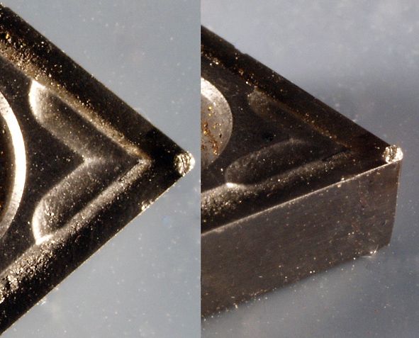
                                                If it happens again, I suggest that you take the tip out and put it under a lens. If you see something like this:

                                                bue4.jpg

                                                then BUE is the problem. The photographs are actually steel on a Sumitomo titanium carbide tip, NSC geometry, which identifies the complex forms of the chip forming bits on tip.

                                                Andrew, re pedantry… feel free! I use the 'correct' equations when calculating things with Mathcad, which tracks units and ensures consistency. But I think the crude 'torque x RPM' version gives a better sense of things to many people who might not be quite so familiar with mathematical rigour. As long as they don't try and do any sums with it, of course!

                                                Russell: the height tolerances are for turning, facing is not so critical, but they're manufacturers recommendations, not mine! Obviously, you're right, as diameter reduces, the tool angles change if not exactly on centre height – rake, as well as clearance.

                                                As diameter reduces it does, theoretically at least, become more important to get closer to centre height, but in my experience it doesn't seem to matter very much, and I can turn very small diameters without difficulty, without getting over-fussy about centre height. As long as it's not above centre height, of course.

                                                However, you need the right tip to do it – have a look at the edges of the Sumitomo NSC tip above, you'll see that, by carbide tip standards, they're quite sharp. Some (many?) tips have rounded edges, which limit their minimum depth of cut and minimum diameter.

                                                Oh yes, whilst looking at that tip – set the tip of the tip to centre height, keep the gauge well away from the chipbreaker parts – the Sumitomo NSC shapes are significantly HIGHER than the very tip of the insert, so sitting the gauge thereon would result in setting the tip far too low.

                                                Ah, could that be Martin's problem with that spirit level height gauge that he uses?

                                                #129431
                                                KWIL
                                                Participant
                                                  @kwil

                                                  I agree with JasonB, when facing across a large diameter I keep one hand on the speed control of the VFD, (I have a geared potentiometer) which allow a variable rate to be applied. Some DROs (and I did not choose this optionsad ) will do this for you as it is measuring radius and hence can calculate the necessary rpm.

                                                  As regards far eastern inserts, the Korloy AK inserts are available as CCGT 060202-AK etc for aluminium. Grade NC5330 works very well on stainless.


                                                  Edited By KWIL on 12/09/2013 13:52:05

                                                  #129438
                                                  Cabeng
                                                  Participant
                                                    @cabeng

                                                    JasonB:

                                                    Would it be possible for Caneng to suggest a few suffixes that we should look out for that would be suitable on hobby lathes

                                                    Blunt answer – no! Each manufacturer has his own designations, new ones are forever appearing, and some are for very specific cutting operations in specific materials.

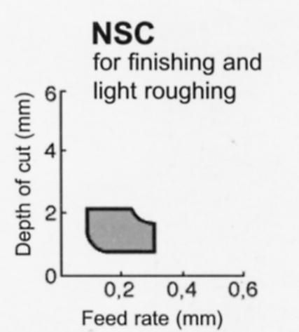
                                                    I can, however, give some guidance based on experience. But before I start, I do not work for, and never have worked for, Sumitomo! I came across their tips umpty-one years ago, and the recommendation to try them out has been so succesful that I've never had any urge to use anything different for most of my work. They've cut steel, hardened steel, HSS, cast iron, stainless steel, copper, phosphor bronze, Tufnol, Floursint, even wood – just about everything except aluminium. All sorts of diameters and shapes, hexagon bar, square bar, rough and hard castings. So they do provide a good basis for identifying what a model engineer might want to write down as a purchasing specification for his tips. Here's the Sumitomo diagram that identifies the cutting region for the NSC geometry:

                                                    -nsc.jpg

                                                    From that we get that the NSC geometry is intended to operate with depth of cuts in the range 0.5 – 2mm (0.020" – 0.080" ) and feed rates of 0.1 – 0.3mm/rev (0.004" – 0.012" ). Within those ranges they will cut and CHIP FORM exactly as their designer intended. However, they will work outside those ranges, albeit without 'correct' chip forming – but acceptable in a model engineering, non-production environment. I've used them down to 0.002"/rev feed (slow feed tumbler gear on the S7) with depth of cut from say half a thou up to 0.125" – that photograph of the swarf was 3mm d.o.c., can't remember the feed, probably 0.004"/rev., but definitely not chip forming correctly!

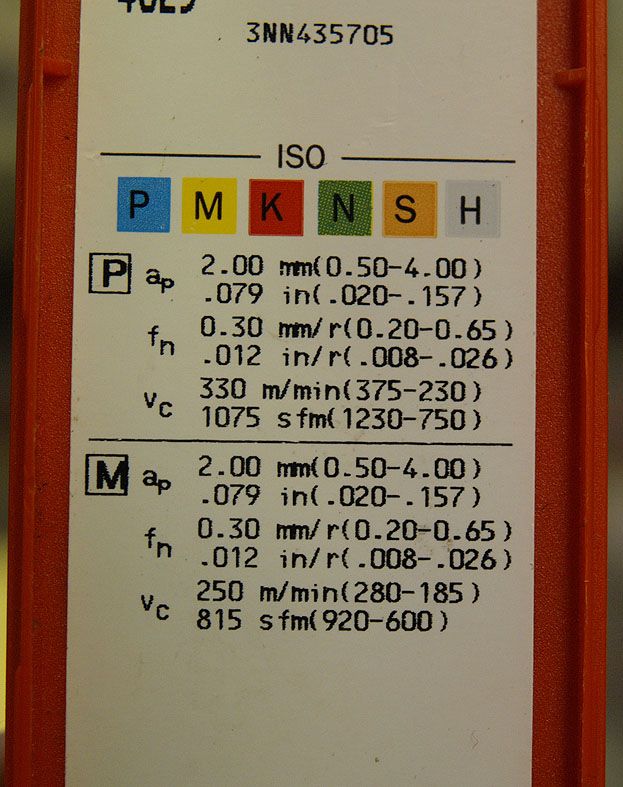
                                                    So a tip that will do d.o.c. 0.5 – 2 mm at feed 0.1 – 0.3mm/rev would be a good starting point. These tips would not be suitable:

                                                    data2.jpg

                                                    ap is the d.o.c., fn is the feed range, Vc is the cutting speed. Don't worry about cutting speed, not significant for model engineers, and they'll all work outside those ranges. The speed ranges are for 15 minute tool life – cut faster and they'll wear out quicker, cut slower and they'll last longer. We're not worried about optimising tool life, and they'll all go faster than we would need anyway!

                                                    The coloured letters are the material classifications for which the tip is designed: P is virtually all 'normal' steels – unalloyed, low alloy, high alloy, cast steels. M are the stainless steels, K are the cast irons, plus aluminium alloys. The others are not relevant to model engineering activities. Well, maybe if you're building gas turbines…

                                                    The presence of cutting data for P and M materials shows that the tool is suited to cutting steels and stainless steels. But it would probably cut K as well, perfectly satisfactorily for our purposes, but not optimised for high performance on cast iron in industry.

                                                    Carbide grade – not something to get hung up on in any detail, we're not in need of optimising everything for production, so we can use less than optimum materials. I would suggest going for titanium carbides (cermets) or coated carbide grades, as these are good for minimising (but unfortunately not eliminating) BUE problems. The gold clour on tips is titanium nitride, so it's obvious that they're coated. But be aware that some coatings (e.g. Al2O3) are not gold, so not being gold coloured doesn't necessarily mean that it's not coated.

                                                    Coatings are also present to reduce things like flank wear on the tips, it's not all about BUE

                                                    Tip radius 0.2mm. Not as strong as 0.4mm, but a lot less trouble on a small machine.

                                                    But one thing you should NOT do is to buy el cheapo tips from a second hand tool dealer at an exhibition. And NEVER buy tips that are just piled up in a box where you rummage about for something that looks right Only buy tips in original boxes, and only in sealed boxes at that – if the seal is broken, don't touch 'em. I did that once, having dropped on a full box of Sumis at a good price – they wouldn't cut properly, and a trip to the microscope showed that every one was worn! Fortunately they were from a decent source and I got my money back. But I've never bought from them since that experience. Plenty of industrial grade suppliers around, better to stick to them as the source for your tips.

                                                    That's about the best I can do on advice, but for recommendations:

                                                    Sumitomo tips in T1200A titanium carbide, NSC chip breaker for turning and facing. For Martin's tool holders, CCGT060202-NSC/T1200A.

                                                    Sumitomo T1200A again for boring tools, but with the W chip breaker, it's brilliant. Beware – the W chip former is assymetrical, you will need the L (left) version for normal going right-to-left boring operations.

                                                    Parting – only ever used Iscar tips and blades. Tried several variants of carbide, coating, chip former, never found much difference between them. Problem with parting tools is that blades and tips are manufacturer specific – an Iscar blade will only take Iscar tips, you can't mix manufacturers.

                                                    Hope that helps!

                                                    Edited By Cabeng on 12/09/2013 15:03:18

                                                    Edited By JasonB on 12/09/2013 15:59:24

                                                    #129439
                                                    Cabeng
                                                    Participant
                                                      @cabeng

                                                      Who or what put those ~@^&^^%$ smileys in after I'd posted that message? Not me! I deleted them, and somthing or other has put them back.

                                                    Viewing 25 posts - 1 through 25 (of 57 total)
                                                    • Please log in to reply to this topic. Registering is free and easy using the links on the menu at the top of this page.

                                                    Advert

                                                    Latest Replies

                                                    Viewing 25 topics - 1 through 25 (of 25 total)
                                                    Viewing 25 topics - 1 through 25 (of 25 total)

                                                    View full reply list.

                                                    Advert

                                                    Newsletter Sign-up