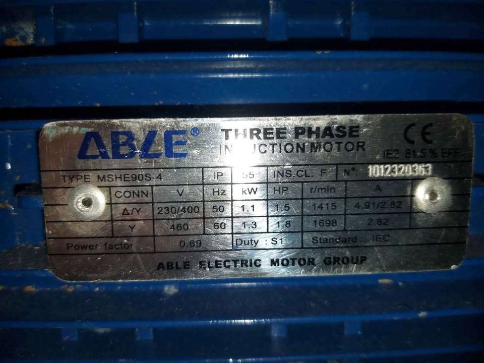
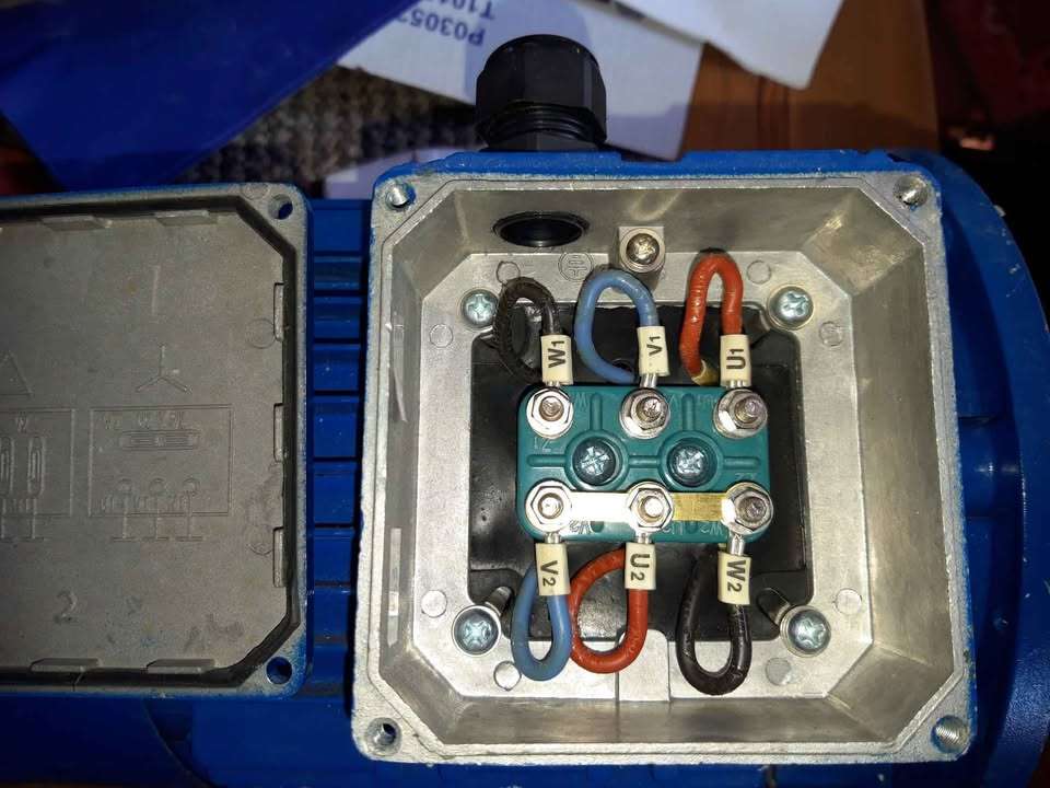
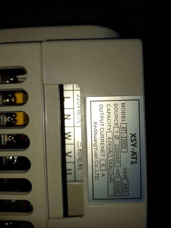
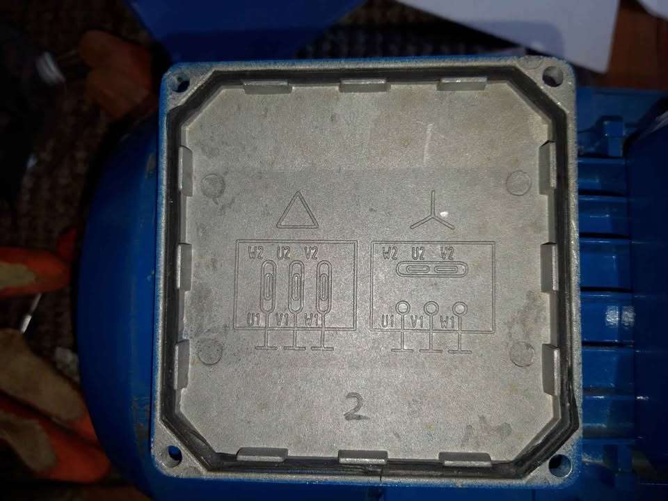
How to wire up 3 phase motor and 3 phase converter?
How to wire up 3 phase motor and 3 phase converter?
- This topic has 15 replies, 8 voices, and was last updated 6 April 2025 at 20:17 by
 old mart.

- Please log in to reply to this topic. Registering is free and easy using the links on the menu at the top of this page.
Latest Replies
-
- Topic
- Voices
- Last Post
-
-
What Did You Do Today 2025
1
2
…
9
10
Started by:
JasonB
in: The Tea Room
- 35
-
27 August 2025 at 16:55
Durhambuilder
-
Marcus Oxen … illustrated notebook
Started by:
Michael Gilligan
in: The Tea Room
- 2
-
27 August 2025 at 16:45
Harry Wilkes
-
Weird electric actuator action
Started by:
ell81
in: Beginners questions
- 3
-
27 August 2025 at 16:41
Harry Wilkes
-
Lathe tool inserts
Started by:
Andy Brocklehurst
in: Beginners questions
- 9
-
27 August 2025 at 14:21
Vic
-
Museum donation
Started by:
Stephen Wessel 1
in: Introduce Yourself – New members start here!
- 4
-
27 August 2025 at 13:06
Michael Gilligan
-
Softening epoxy
1
2
Started by:
John Haine
in: General Questions
- 21
-
27 August 2025 at 12:56
Robert Atkinson 2
-
Granville lathe leadscrew change wheel
1
2
Started by:
JACK SIDEBOTHAM
in: Help and Assistance! (Offered or Wanted)
- 13
-
27 August 2025 at 12:09
cogdobbler
-
Hereward
Started by:
Richard Simpson
in: Model Boats
- 6
-
27 August 2025 at 11:06
cogdobbler
-
Imperial Bearing Surprise!
Started by:
Peter_H
in: General Questions
- 4
-
27 August 2025 at 10:06
tonychap
-
QCTP for chester lathe
1
2
Started by:
Chris12
in: Beginners questions
- 12
-
27 August 2025 at 08:17
Vic
-
Bending copper tube?
Started by:
Bo’sun
in: Workshop Techniques
- 13
-
27 August 2025 at 02:05
cogdobbler
-
Damp engine, Name?
Started by:
sivtek1
in: Stationary engines
- 5
-
27 August 2025 at 00:00
John Purdy
-
The skill of the Victorian woodcut engraver
Started by:
vic newey
in: The Tea Room
- 5
-
26 August 2025 at 22:12
SillyOldDuffer
-
Smart & Brown Model L lathe help required
Started by:
AJAX
in: Manual machine tools
- 4
-
26 August 2025 at 21:40
AJAX
-
Myford VMB mill, head lift.
Started by:
lctikka61
in: Manual machine tools
- 3
-
26 August 2025 at 20:41
Alan Wood 4
-
Raab Style Heibluftmotor
Started by:
JasonB
in: Miscellaneous models
- 3
-
26 August 2025 at 18:53
JasonB
-
3.5″ Derby 4F – First Loco Build
Started by:
mattleicester
in: Locomotives
- 5
-
26 August 2025 at 17:51
paul rushmer
-
Phone Phreaking
Started by:
Michael Gilligan
in: Clocks and Scientific Instruments
- 12
-
26 August 2025 at 15:28
simondavies3
-
3″ Castings – Help/Advice needed
Started by:
Andy Porter 1
in: Traction engines
- 5
-
26 August 2025 at 12:37
parovoz
-
Valve gear problem
Started by:
John Billard 1
in: Locomotives
- 3
-
26 August 2025 at 09:08
Charles Lamont
-
Recommendations for book on clock repairs
Started by:
Andy Stopford
in: Clocks and Scientific Instruments
- 8
-
25 August 2025 at 21:15
Andy Stopford
-
Drain Cock search
Started by:
Speedy Builder5
in: Locomotives
- 4
-
25 August 2025 at 16:48
Diogenes
-
Blackgates 3 Way Toolpost Casting
Started by:
John McCulla
in: Materials
- 15
-
25 August 2025 at 16:06
Nicholas Farr
-
Quartz clock movement
Started by:
duncan webster 1
in: Electronics in the Workshop
- 4
-
25 August 2025 at 10:24
Michael Gilligan
-
Milling for beginners book, Where?
Started by:
andy198712
in: Beginners questions
- 8
-
25 August 2025 at 09:16
andy198712
-
What Did You Do Today 2025
1
2
…
9
10


