help identifying gear module or dp

Advert

help identifying gear module or dp

Home Forums General Questions help identifying gear module or dp

Viewing 25 posts - 1 through 25 (of 28 total)
  • Author
    Posts
  • #518274
    Richard Cox
    Participant
      @richardcox82602

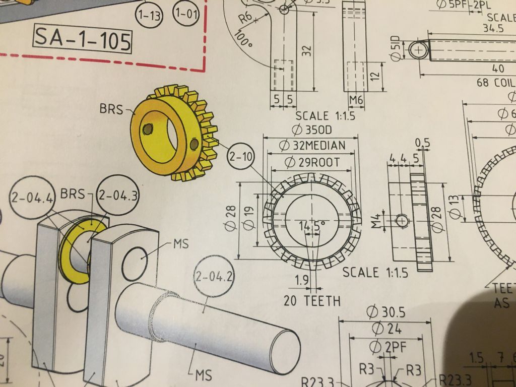
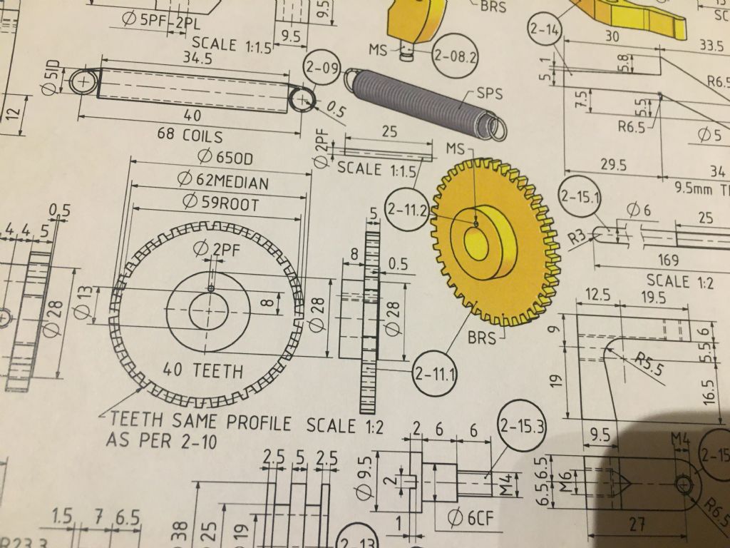
      Evening gents I’m looking over plans of an engine I’m planning to build in the future and unsure on the gears needed see pic, the plans are all in metric however the gears appear to be 16dp also the pressure angle is 14.5, for example the small gear od of 35mm which I think would be the blank size comes out at 1.59 module unavailable obviously or 16dp, can any one shed any light or am I reading it wrong if it is in dp weird that the gears all metric and annoyingly misses out the module or dp on the plan thanks Rich


      4d1a0f1a-4664-479d-8f2d-ab5ada32a53a.jpeg

      Engine

      Edited By Richard Cox on 07/01/2021 21:50:21

      Edited By Richard Cox on 07/01/2021 21:52:36

      Advert
      #27880
      Richard Cox
      Participant
        @richardcox82602
        #518276
        Michael Gilligan
        Participant
          @michaelgilligan61133

          You might find my post near the end of this page useful, Richard: **LINK**

          https://www.model-engineer.co.uk/forums/postings.asp?th=169969&p=2

          MichaelG.

          #518277
          Richard Cox
          Participant
            @richardcox82602
            Posted by Michael Gilligan on 07/01/2021 21:50:43:

            You might find my post near the end of this page useful, Richard: **LINK**

            https://www.model-engineer.co.uk/forums/postings.asp?th=169969&p=2

            MichaelG.

            I will have a read thanks Michael 

            Rich

            Edited By Richard Cox on 07/01/2021 22:00:04

            #518315
            JasonB
            Moderator
              @jasonb

              Which of his engines is it, can you post a link to the plans

              One of the problems is he often scales up the original drawings and combine that with his CAD package not showing many decimal figures errors creep in. Ideally we need to know the gear centres but you may be lucky if that hit & miss engine mounts the cam gear on an eccentric stud as you will get some adjustment of the mesh. For example if the PCD or median of the smaller gear were shown to two decimal places it would be 31.75mm which makes 16DP the ideal size.

              Edited By JasonB on 08/01/2021 07:18:02

              #518361
              JasonB
              Moderator
                @jasonb

                A bit of digging and his engine is a doubled up Kerzel with most sizes rounded to nearest whole mm .This engine used 32DP gears so 16DP would be the best option and locate the position for the regulator arm pivot by using the actual gears to get the spacing which should be in the region of 47.63mm not the 47 on the drawing. That's what you get when two separate diameters are rounded up but the single ctr to ctr rounded downangry!.

                You could also get away with pushing the position of the pivot out to 48mmPCD which would allow you to use cheapish off the shelf 1MOD gears from the likes of beltingonline at 32/64T or 1.5Mod at 21/42 would give PCD of 47.25mm

                Edited By JasonB on 08/01/2021 10:47:23

                #518386
                Anonymous

                  Whoever "designed" this engine clearly knows nothing about gears. The teeth are simply isoceles trapezoids and the included angle is incorrect for the assumed pressure angle. It's half what it should be. As drawn the addendum and dedendum are the same, which is incorrect. There's no clearance allowed. sad

                  There are two choices. One tweak the position of the gears to enable use of a standard DP or Mod value as described by Jason above. Two, stick with the "median" values as shown (treat them as pitch circle diameters) and make special cutters for whatever the value of DP or Mod comes out as. Jason illustrated some simple flycutters with circular profiles for cutting gears in another recent thread. That should be fine in this application. The choice depends upon whether the OP wants to make, or buy, the gears.

                  Andrew

                  #518389
                  Phil P
                  Participant
                    @philp

                    I dont know about anyone else, but I find those drawings with everything crammed onto a couple of sheets are really confusing and unclear.

                    In my job at work I have to produce sets of drawings for complex bespoke machines, and if I issued them in this format I would be shown the door pretty quickly. It is one sheet per part where I work, and that is how I do my own personal drawings as well.

                    I suppose model engineers are more tolerant of this kind of thing than is the case in an industrial background.

                    Phil

                    #518395
                    Nicholas Farr
                    Participant
                      @nicholasfarr14254

                      Hi Phil P, I guess commercial enterprises can pass the cost of multiple drawings on to their customers, model engineers that do things as a hobby can't pass costs on to anyone, and even an all-in-one drawing is not always cheap. (all due respects considered)

                      Regards Nick.

                      #518399
                      JasonB
                      Moderator
                        @jasonb

                        In this day and age the cost is probably less of an issue as they are not being printed and shared but distributed electronically. I suppose the end user may save a bit of paper cost but as Julius tends to draw on A3 his sheets are not that home user friendly. I do feel spacing them out a bit more would make it easier to follow though.

                        Richard if you have not done so already then visit this page and open the links at the bottom to the original drawings and build notes

                        #518403
                        Richard Cox
                        Participant
                          @richardcox82602
                          Posted by JasonB on 08/01/2021 10:43:52:

                          A bit of digging and his engine is a doubled up Kerzel with most sizes rounded to nearest whole mm .This engine used 32DP gears so 16DP would be the best option and locate the position for the regulator arm pivot by using the actual gears to get the spacing which should be in the region of 47.63mm not the 47 on the drawing. That's what you get when two separate diameters are rounded up but the single ctr to ctr rounded downangry!.

                          You could also get away with pushing the position of the pivot out to 48mmPCD which would allow you to use cheapish off the shelf 1MOD gears from the likes of beltingonline at 32/64T or 1.5Mod at 21/42 would give PCD of 47.25mm

                          Edited By JasonB on 08/01/2021 10:47:23

                          yes you are correct jason not had chance to reply at work, I looked into the metric version which is x2 as he easier for me working in metric,

                          #518404
                          Richard Cox
                          Participant
                            @richardcox82602
                            Posted by Phil P on 08/01/2021 12:12:18:

                            I dont know about anyone else, but I find those drawings with everything crammed onto a couple of sheets are really confusing and unclear.

                            In my job at work I have to produce sets of drawings for complex bespoke machines, and if I issued them in this format I would be shown the door pretty quickly. It is one sheet per part where I work, and that is how I do my own personal drawings as well.

                            I suppose model engineers are more tolerant of this kind of thing than is the case in an industrial background.

                            Phil

                            Hi Phil yes agree it’s a bit messy and confusing I don’t see it would of been much hardship to spread it out a bit, the whole engine is on 5 sheets and only two are the actual components

                            Rich

                            #518407
                            SillyOldDuffer
                            Moderator
                              @sillyoldduffer
                              Posted by Andrew Johnston on 08/01/2021 12:00:43:

                              Whoever "designed" this engine clearly knows nothing about gears. The teeth are simply isoceles trapezoids and the included angle is incorrect for the assumed pressure angle. It's half what it should be. As drawn the addendum and dedendum are the same, which is incorrect. There's no clearance allowed. sad

                              There are two choices…

                              Andrew

                              I agree with Andrew in that the teeth are simple trapezoids, not cycloidal or involute curves. But it may be deliberate rather than bad design. In the good old days millwrights and early engine makers didn't understand the maths behind gear shapes so it was common practice to approximate a shape and let the teeth grind themselves in. It's not a good system; at first the teeth are too tight and have to be filed to run at all, then they run inefficiently with much friction and wear out quickly. But it works and crude straight teeth are easy to make with a file. No need to worry about module, DP and gear cutting – the builder just needs to follow the plan, produce a bodged gear, and then fettle the teeth to mesh approximately.

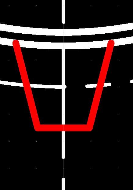
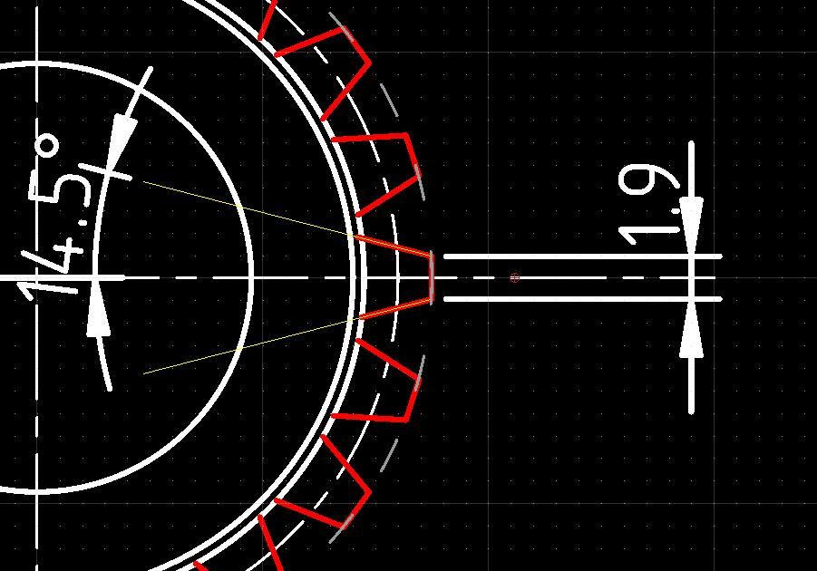
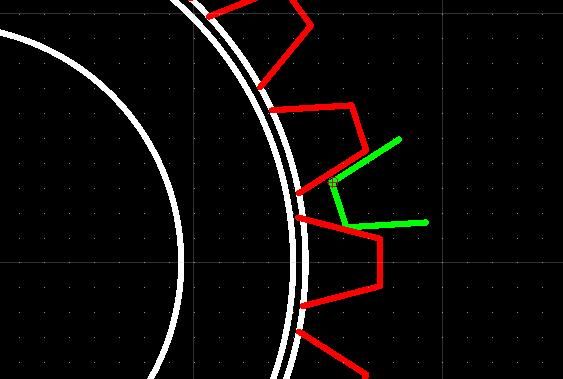
                              Zooming in on the drawing shows all the information is there; I've redrawn it for emphasis.

                              The shape:

                              toothzoom.jpg

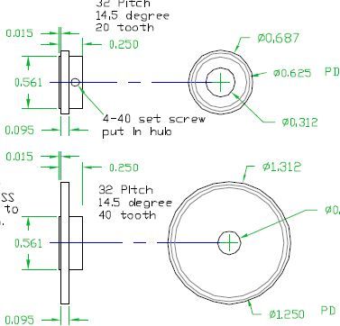
                              With dimensions, 14.5° each side, 29° in total:

                              toothzoomdims.jpg

                              This last image shows how yuk the initial mesh is, and it's obvious the teeth will quickly wear to a more sensible shape at the top.

                              teethmesh.jpg

                              Nice job for a 3D printer. Easy to knock a couple of gears as per drawing and test them.

                              Dave

                              Edited By SillyOldDuffer on 08/01/2021 13:35:26

                              #518415
                              JasonB
                              Moderator
                                @jasonb

                                More likely just down to the limitations of the CAD package used. In the days of pen and pencil and basic CAD you would probably have just got 3 circles much like the original Kerzel drawing. Julius has tried to represent a gear no doubt by drawing a single approximation to a tooth and then doing a circular pattern ( done it myself in the past). Now I'd use a Script in Alibre or FMGears in F360 to get a proper representation with the rounded gear faces..

                                Same with threads, couple of lines has done us for many years, Alibre now gives me the option of "textured threads" on drawings or I can slow the whole 'puter up by doing a helical cut to make the part actually look threaded.

                                One other comment on the gears it does not really matter if you use 14.5 or 20PA so long as both gears are the same so that may open up your choice of bought cutters. 14.5PA will look a bit more like old gears.

                                kerzel gears.jpg

                                Edited By JasonB on 08/01/2021 13:55:25

                                #518423
                                Anonymous
                                  Posted by SillyOldDuffer on 08/01/2021 13:34:59:

                                  With dimensions, 14.5° each side, 29° in total……

                                  Indeed, but that's not what was orginally drawn. The angle dimensioned is the included angle, not the correct half angle.

                                  Andrew

                                  #518432
                                  Anonymous
                                    Posted by JasonB on 08/01/2021 13:54:09:

                                    More likely just down to the limitations of the CAD package used.

                                    Somehow I doubt it. The three circles are not correct and the drawing clearly states that the profile of the larger gear teeth are the same as the smaller gear. It's firmly in the SoD file 'n' fudge camp. Which may be fine for a windmill with wooden gears but I suspect it'll be more of an issue with a hit 'n' miss engine.

                                    Andrew

                                    #518434
                                    JasonB
                                    Moderator
                                      @jasonb

                                      The construction is all a bit hit and miss with them, that's why I suggested spacing the gears on the actual job.wink 2

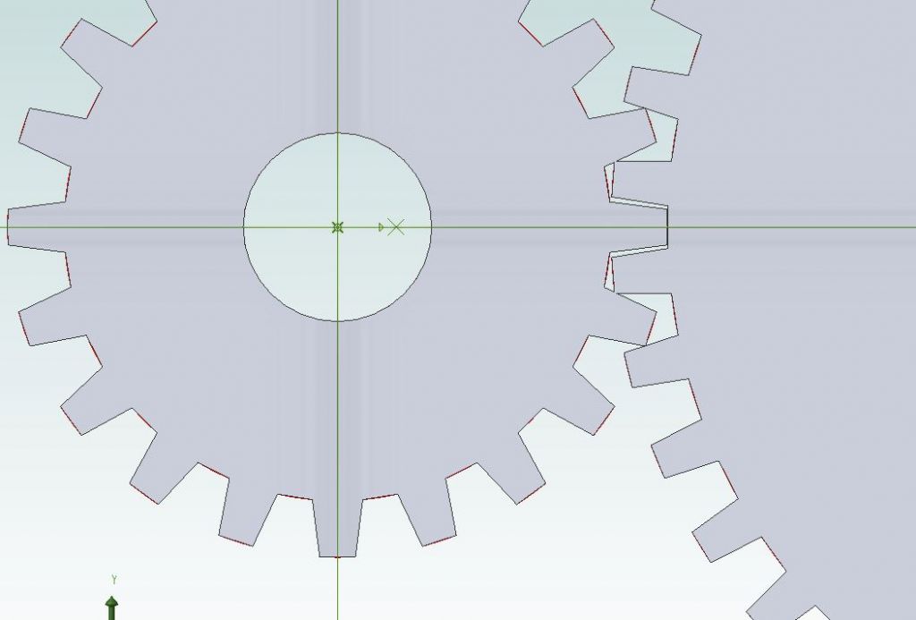
                                      As you say the lack of clearance at the bottom of the cuts will clash and there is also a bit of corner rubbing when actually drawn out to what's on JDW's drawing.

                                      kerzel gears 2.jpg

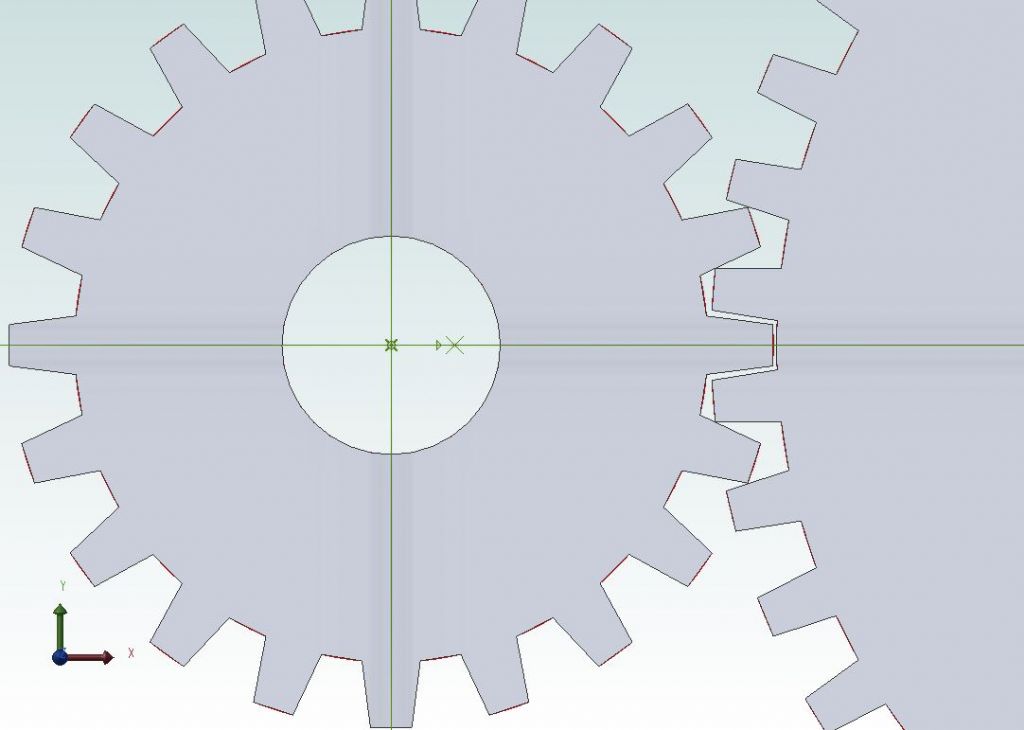
                                      If cogs gears were set with a bit of paper between or set out at 47.15 mm rather than 47mm they will clear but will make a bit of a racket.

                                      kerzel gears 3.jpg

                                      Edited By JasonB on 08/01/2021 15:00:21

                                      #518444
                                      SillyOldDuffer
                                      Moderator
                                        @sillyoldduffer
                                        Posted by Andrew Johnston on 08/01/2021 14:17:14:

                                        Posted by SillyOldDuffer on 08/01/2021 13:34:59:

                                        With dimensions, 14.5° each side, 29° in total……

                                        Indeed, but that's not what was orginally drawn. The angle dimensioned is the included angle, not the correct half angle.

                                        Andrew

                                        Whoops, well spotted sir! Another Silly Old Duffer mistake nailed,

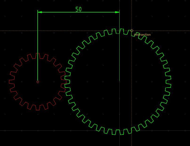
                                        Assuming the design is a deliberate fudge, the sort of thing I do, the redrawn gears work better:

                                        teethboth.jpg

                                        Is it a coincidence my axles end up exactly 50mm apart? I don't have the plan.

                                        Dave

                                        #518448
                                        Anonymous
                                          Posted by SillyOldDuffer on 08/01/2021 15:19:59:

                                          Whoops, well spotted sir! Another Silly Old Duffer mistake nailed

                                          SoD, you're getting paranoid. It's the original drawing that is incorrect, not you.

                                          Andrew

                                          #518450
                                          JasonB
                                          Moderator
                                            @jasonb

                                            47mm cts on the plan Dave, though not given directly it can be worked out either by the part they fit to or using what's in the first post and treating the median as the PCD then it's( PCD A + PCD B) / 2

                                            Moving it 3mm will start to give other problems like the governor arm not engaging with the spool.

                                            #518466
                                            Richard Cox
                                            Participant
                                              @richardcox82602
                                              Posted by JasonB on 08/01/2021 13:03:16:

                                              In this day and age the cost is probably less of an issue as they are not being printed and shared but distributed electronically. I suppose the end user may save a bit of paper cost but as Julius tends to draw on A3 his sheets are not that home user friendly. I do feel spacing them out a bit more would make it easier to follow though.

                                              Richard if you have not done so already then visit this page and open the links at the bottom to the original drawings and build notes

                                              Cheers Jason I have been there yes and downloaded, I’m sure David mentioned metric drawings were available I tried emailing with no response but the original was years old, that’s how I stumbled on the x2 metric version,

                                              thanks for the other comments lads

                                              #518470
                                              Richard Cox
                                              Participant
                                                @richardcox82602

                                                I admire what some of you lads can do with cad I can only dream, I keep toying with the idea of getting into it but not really got the need bit of a catch 22 really to get good at something you need to always do it (keep practising) and not really having the need nothing to practice with lol, I’ve played with fusion360 did a few tutorials, and downloaded free cad,

                                                Rich

                                                #518473
                                                SillyOldDuffer
                                                Moderator
                                                  @sillyoldduffer
                                                  Posted by Andrew Johnston on 08/01/2021 15:41:23:

                                                  Posted by SillyOldDuffer on 08/01/2021 15:19:59:

                                                  Whoops, well spotted sir! Another Silly Old Duffer mistake nailed

                                                  SoD, you're getting paranoid. It's the original drawing that is incorrect, not you.

                                                  Andrew

                                                  Nah, still guilty. When I drew the gear it felt wrong but I carried on regardless thus missing an error I should have noticed. A little embarrassing because redrawing plans to spot mistakes and make sure I've understood properly is one of the main reasons I use CAD…

                                                  Dave

                                                  #518486
                                                  Nick Wheeler
                                                  Participant
                                                    @nickwheeler
                                                    Posted by Richard Cox on 08/01/2021 16:52:45:

                                                    I admire what some of you lads can do with cad I can only dream, I keep toying with the idea of getting into it but not really got the need bit of a catch 22 really to get good at something you need to always do it (keep practising) and not really having the need nothing to practice with lol, I’ve played with fusion360 did a few tutorials, and downloaded free cad,

                                                    I found modelling my projects in Fusion 360 as I made them was a good way of learning what I need to know.

                                                    #518580
                                                    Anonymous
                                                      Posted by Richard Cox on 08/01/2021 16:52:45:

                                                      I admire what some of you lads can do with cad I can only dream, I keep toying with the idea of getting into it but not really got the need bit of a catch 22 really to get good at something you need to always do it….

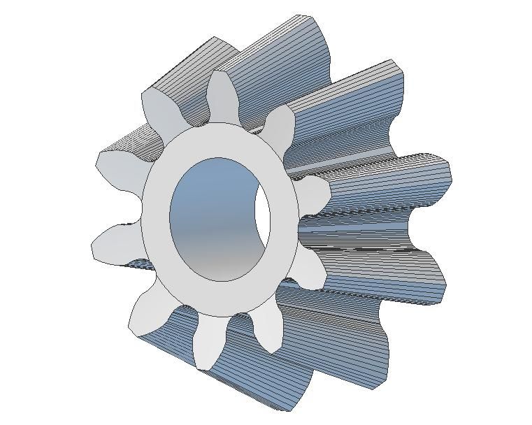
                                                      I'd vote for 3D CAD, it's a darn sight easier than some 2D CAD packages which are are just glorified electronic drawing boards. Practice makes perfect:

                                                      Bevel Gear Pinion 3D Model

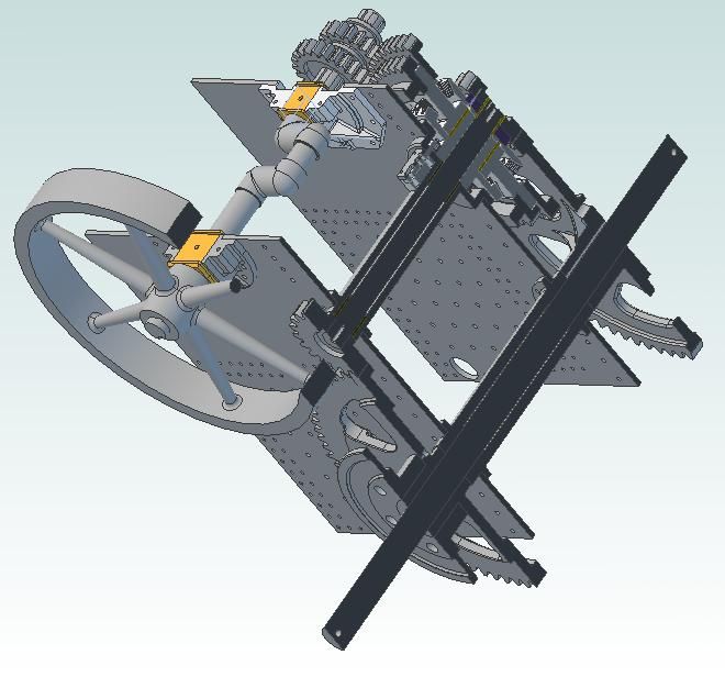
                                                      One big advantage of 3D CAD is the ability to create assemblies and sectional views so that form and fit can be checked before cutting metal:

                                                      Drive Train Assembly

                                                      It is also possible to move assemblies to check clearances at the extremes. On this model of a water pump the minimum clearance between the drive rod and the inside of the ram is 15 thou:

                                                      water pump assembly 2-11-2014.jpg

                                                      And so it proved to be in reality once I'd made the parts. Another plus for 3D CAD is that 2D drawings are simple to create.

                                                      Andrew

                                                    Viewing 25 posts - 1 through 25 (of 28 total)
                                                    • Please log in to reply to this topic. Registering is free and easy using the links on the menu at the top of this page.

                                                    Advert

                                                    Latest Replies

                                                    Home Forums General Questions Topics

                                                    Viewing 25 topics - 1 through 25 (of 25 total)
                                                    Viewing 25 topics - 1 through 25 (of 25 total)

                                                    View full reply list.

                                                    Advert

                                                    Newsletter Sign-up