Hi Pete Rimmer, I'm very happy to hear from you so soon after I joined the group.
I can tell you are very keen to get the HLV going again.
The KL-1 differs from the HLV-H mainly in the pedestal base only. The "top half" stayed the same for both. I worked in the drawing office and was given the job of taking the new American KL drawings and modifying it for manufacture in Exeter, to update our HLV-H (which we referred to as the LH since most part numbers started with that, and it was shorthand) in line with our American bosses. The changes for our build were a new electric panel and cabinet, switches, speed control panel (on top of the headstock), pedestal tray, swing out collet boards, coolant pump and housing (now behind the tailstock). Items such as the 2 speed, reversing, main motor, it's mounting plate driving belts (especially made for Hardinge by Goodyear, so you can't substitute common made stuff, they don't fit. Similarly Hardinge had bearings made to specific sizes – you could buy replacements only from them!), variable speed pulley was the same etc.
The 0.5/1.5 HP main motors made by Newman Motors, Yate, Bristol were the best – I had to reverse the internal parts to allow this motor to be used in the DV/DSM 59 range that I built. This was changed to what we fitters didn't like, a 2 HP Brown Boveri motor that was finicky to align and made an awful yowling sound on startup! Perhaps Newman's were becoming short in supply, I don't know, but I made sure I never fitted Brown Boveri in my much loved DV/DSMs (I built about 300 in my time)!
Our Exeter factory turned out a target average of 32 finished machines per month, with accessories and sub-assemblies too.
Your Feltham factory built HLV. Original specs for headstock alignment was precision testbar looking down over the bedplate, max 0.0005" in 6", looking towards the operator, max 0.0001" in 6", turning test over 2 brass rings of min 2" dia, zero to 0.0002" small at the tailstock end. A facing test carried out on a circular aluminium face block, about 5" dia had to show a 1/2” wide ring on the outside edge of the face, no spokes or inner rings, checked with micrometer blue on a precision face plate. Tailstock height 0.0005" to 0.0010" above headstock, looking up 0.0000" to 0.0002" in 6", looking towards the operator, max 0.0001" in 3", turning tests between 2 solid centres over 2 brass rings of min 2" dia, zero to 0.0002" small at tailstock end with the tailstock spindle IN. With the tailstock spindle OUT the same result but the IN had to be less error than the OUT figure. So a result of 0.0001" IN, 0.0002" OUT was accepted, but NOT the other way around. Carriage shake (slack on the bedplate, both ends of carriage) max 0.0002". Cross slide shake max 0.0005", same as the toolpost. Feedscrew backlash max 2 divisions checked on any dial. I quote these specs only for your interest and to give you an idea of what is important on a new machine.
You will have a good time trying to achieve these goals, I'm sure, since spare parts are no longer made and you will have no access to special test bars and alignment components, but from what you have already done, it sounds like you will be able to get reasonable results.
Best wishes, Barry Stone, clock number HMT35, back in the "good old days". I also spent a few years rebuilding these machines for ZMT Services (just outside Exeter) with Paul Soper and Ken Goddard.
Pete Rimmer.


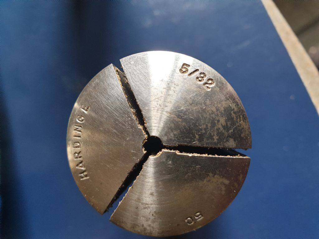
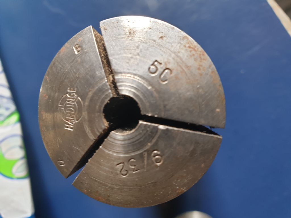
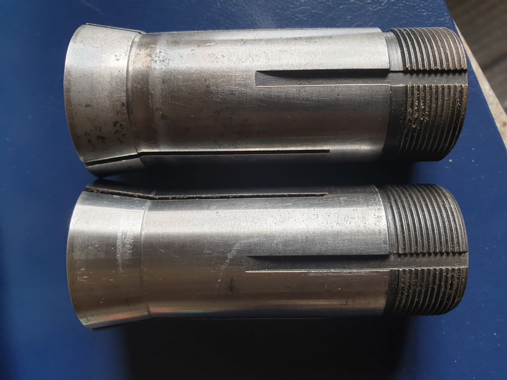
 looks correct but the lower one, 9/32" was not made in UK, in my opinion. It may be an American one, the circular collet design with Hardinge stamped through it is not an English factory 'thing'. It has added stampings "O" and "B" – I'm not familiar with this, it could have been made as elsewhere as a copy (Hardinge lathes were copied by a few foreign companies, including a Taiwan company called Feeler but their parts would not fit the genuine factory built machine). The spindle back bearing diameter is nominally 1.2500" with an exceptionally tight tolerance of +0.0001" if I remember correctly. Collet back bearing (you describe as just before the thread), I believe, has a diameter of 1.2498" tolerance of only -0.0003". The body length measures from the 10 degree head angle. Bore diameter max runout is 0.001" at a point 1" from the front face. The spindle collet key entering the back bearing is locked in place with a short, #10-32 UNF, grub screw, and is set for depth of engagement against a special gauge.

