It would help you gain more specific advice if you tell us what you building, and with what equipment; but I can offer some general points:
.
Yes, model-engineering is predominantly Imperial at least for scale-model designs, but it is not universal, and if as you hint you are designing your own project you can decide metric or Imperial throughout; and choose the gears accordingly.
'
You select the wheel sizes by the torque they need transmit and the space available for the ratios needed; but I would go for the coarse rather than fine for the given diameters, with the proviso that you try to avoid needing make pinions with very small teeth-counts. They seem to start getting awkward below about 15 teeth.
Consequently there is no "typical" size for model gears, any more than there is a "typical" size for them in any machinery, such as your car. They are sized, and the material chosen, for the application.
If your project is a scale model of some fairly common type you could try examining representative examples to see what they use. As a rough guide to power, consider what might be in your machine-tools or powered DIY equipment; but square-laws on scales tend to work in the favour of strength for force.
How big is a gear?
– The DP pitch circle diameter is [Tooth-count / DP number] in inches.
So an 80T 20DP wheel is of 4" PCD.
– Metric module pitches: PCD = [Tooth-count X Module].
So an 80T 1.5 Mod wheel is of 120mm PCD.
– Plus twice the addendum in each case.
'
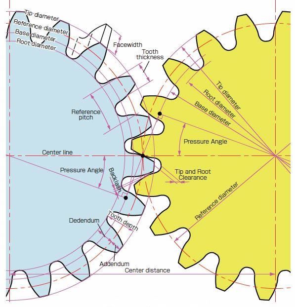
The Pressure-angle on modern gears is usually 20º whether mm or inch sizes: module or circular pitch. The only rule really is that you must not try to mix wheels of different pressure-angles because though they might apparently mesh they will not do so correctly, leading to rapid wear.
.
The cutters, at least in DP sizes, are made in tooth-count ranges; and the geometry dictates the fewer the teeth on a gear, the small the count-range a given cutter can produce; so if you need a large variety of low-count wheels you end up with lots of cutters.
.
Before you start buying costly gear-cutters, study gears and basic gear-cutting! I think you have started that, so please forgive me if I am stating the obvious.
A professional engineers' book on the subject will swamp you in Very Advanced Trigonometry and PhD-level stress-calculations from Page One, not tell you how to make them.
All the theoretical and practical information you or I are likely to need for model-engineering is condensed into books such as:
Law, Ivan; Gears and Gear Cutting; 'Workshop Practice Series no.17', pub. Special Interest Model Books, latest 2003.
Marshall, A.W.; Gear Wheels and Gear Cutting; first pub. 1947; facsimile reprint, TEE publishing, 1994.
Look first in the TEE Publishing's catalogue: TEEpublishing.co.uk.
I happen to own both, hence able to give the formal references, but Law's is the more up-to-date. He also tells you how to make single-tooth (per side) cutters that generate involute-arc teeth. Although I'm not sure I'd make a habit of cutting hefty steel gears with those or any other fly-cutter type tools, thanks to their hammering action on the poor machine-tool.
.
Hope that lot helps!
.
Finally, if you decide for the project as a whole you might be safer buying the gears, they won't earn you Brownie Points but it is common manufacturing-trade practice to purchase stock gears. These have pilot-bored centres and optionally, bosses, amenable to modifying to suit the applications – with very careful machining for concentricity.
 JasonB.


