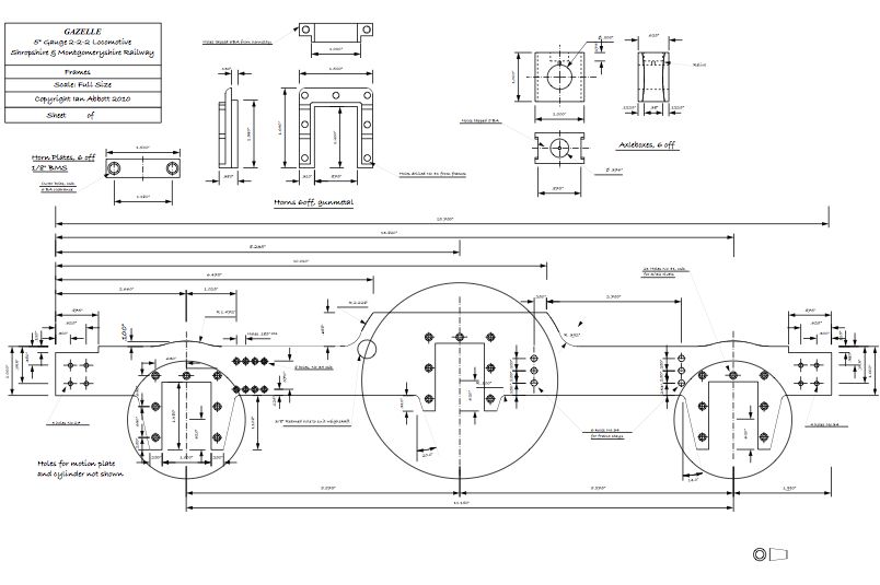
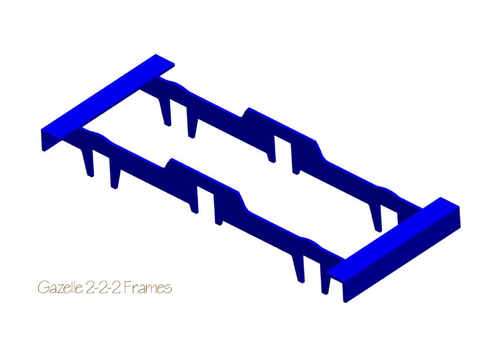
Gazelle 2-2-2 Drawings
Gazelle 2-2-2 Drawings
- This topic has 29 replies, 8 voices, and was last updated 4 May 2018 at 15:32 by
 Ian Abbott.


- Please log in to reply to this topic. Registering is free and easy using the links on the menu at the top of this page.
Latest Replies
-
- Topic
- Voices
- Last Post
-
-
Fobco or a Clarke CMD 1225 milling capabilities? or other recommendations?
Started by:
jacobsmess
in: Workshop Tools and Tooling
- 4
-
7 August 2025 at 20:46
jacobsmess
-
Boiler hydraulic test 4 hours
1
2
Started by:
endckr111
in: Stationary engines
- 13
-
7 August 2025 at 20:30
noel shelley
-
Arc Euro Trade Ltd.
1
2
3
Started by:
Ketan Swali
in: General Questions
- 55
-
7 August 2025 at 20:07
andy198712
-
quality 3 and 4 jaw chucks
Started by:
Steve Huckins
in: Workshop Tools and Tooling
- 2
-
7 August 2025 at 18:23
thisdesignedthat
-
Model Turbines
1
2
…
24
25
Started by:
Turbine Guy
in: Stationary engines
- 28
-
7 August 2025 at 16:44
Turbine Guy
-
Pragotron Slave Clock
Started by:
renardiere7
in: Clocks and Scientific Instruments
- 7
-
7 August 2025 at 16:28
renardiere7
-
Miniature parts maker in Leicester?
Started by:
wilson logan 1
in: Help and Assistance! (Offered or Wanted)
- 2
-
7 August 2025 at 16:11
Michael Gilligan
-
Pratt Bernard Grip true issues
Started by:
teamricky
in: Workshop Tools and Tooling
- 7
-
7 August 2025 at 16:04
teamricky
-
Will iron rivets expand to fill oversized hole?
Started by:
Arthur Jones 2
in: Locomotives
- 6
-
7 August 2025 at 14:41
parovoz
-
UK Steel Supplier? 125 x 125 x 50 BMS
1
2
Started by:
MarkS
in: General Questions
- 14
-
7 August 2025 at 14:03
Journeyman
-
DELL / StarTech [mechanical incompatibilty]
Started by:
Michael Gilligan
in: Electronics in the Workshop
- 3
-
7 August 2025 at 13:11
Michael Gilligan
-
Rotary table Chuck mounting.
Started by:
John Gray 7
in: General Questions
- 8
-
7 August 2025 at 12:31
JasonB
-
Boiler Design – issue 4765
1
2
…
10
11
Started by:
Charles Lamont
in: Model Engineer & Workshop
- 29
-
7 August 2025 at 11:18
JasonB
-
Baumann Buco 1311 clock
Started by:
Clock polisher
in: General Questions
- 1
-
7 August 2025 at 11:10
Clock polisher
-
New member (a young’un)
Started by:
tomread12
in: Introduce Yourself – New members start here!
- 7
-
7 August 2025 at 10:39
parovoz
-
Pre-Setting 4-Jaw Chucks Hack for Quick Centering
Started by:
dbwjbp
in: Workshop Techniques
- 11
-
7 August 2025 at 10:06
noel shelley
-
MD65 leadscrew cross-slide stuck in nut
Started by:
leov
in: Manual machine tools
- 9
-
7 August 2025 at 07:33
Diogenes
-
Bandsaw vs Powered Hacksaw vs Chop Saw?
Started by:
MarkS
in: General Questions
- 18
-
6 August 2025 at 21:53
grubscrew
-
Fobco Star (Universal) Milling capabilities? or a Clarke CMD 1225?
Started by:
jacobsmess
in: Workshop Tools and Tooling
- 1
-
6 August 2025 at 21:26
jacobsmess
-
Save your Swarf!
Started by:
Vic
in: The Tea Room
- 9
-
6 August 2025 at 21:12
Grizzly bear
-
Depth of cut cowells me90
1
2
Started by:
kinross1
in: Manual machine tools
- 14
-
6 August 2025 at 18:39
Richard B
-
Help recommend a milling machine?
1
2
Started by:
richard1989
in: Beginners questions
- 21
-
6 August 2025 at 13:50
Pete
-
Cutting down a linear glass DRO encoder
Started by:
Robin Graham
in: Beginners questions
- 9
-
6 August 2025 at 13:20
Mark Hall
-
Smart Meter Change-over Problems
Started by:
Alistair Robertson 1
in: The Tea Room
- 8
-
6 August 2025 at 11:44
SillyOldDuffer
-
F360 stock from solid
Started by:
Roderick Jenkins
in: CNC machines, Home builds, Conversions, ELS, automation, software, etc tools
- 9
-
6 August 2025 at 10:34
John Haine
-
Fobco or a Clarke CMD 1225 milling capabilities? or other recommendations?
Latest Issue

Newsletter Sign-up
Latest Replies
- Fobco or a Clarke CMD 1225 milling capabilities? or other recommendations?
- Boiler hydraulic test 4 hours
- Arc Euro Trade Ltd.
- quality 3 and 4 jaw chucks
- Model Turbines
- Pragotron Slave Clock
- Miniature parts maker in Leicester?
- Pratt Bernard Grip true issues
- Will iron rivets expand to fill oversized hole?
- UK Steel Supplier? 125 x 125 x 50 BMS

