Facing Error

Advert

Facing Error

Home Forums Beginners questions Facing Error

Viewing 25 posts - 51 through 75 (of 101 total)
  • Author
    Posts
  • #367165
    SillyOldDuffer
    Moderator
      @sillyoldduffer
      Posted by fishy-steve on 13/08/2018 19:12:56:

      Posted by SillyOldDuffer on 13/08/2018 19:01:06:

      Posted by fishy-steve on 13/08/2018 18:29:35:

      I'm talking about backlash in the topslide not the cross slide. The tool can push away with backlash in the topslide. On saying that you would only get a concave face if you were feeding from the bore out. Convex if facing from the outside in.

      Steve.

      Ah, sorry Steve, I misunderstood – with you now. Yes, that was part of the problem and locking the top-slide halved the error.

      Might be able to have a little play before bedtime. As XD says a quick check the lathe is still cutting parallel is worth doing. It was OK last time I checked but …

      Cheers,

      Dave

      Advert
      #367166
      JasonB
      Moderator
        @jasonb
        Posted by Farmboy on 13/08/2018 15:09:22:

        As an inexperienced lathe user I've followed this thread with interest, but I'm struggling to understand the concept of the workpiece rocking in the chuck such that it produces the convex face. I can't imagine how rocking could induce a consistant tapering effect on a rotating face dont know

        Mike.

        If the part was slowly working its way out of the chuck due to poor grip and the draft taper you would get a concave face.

        It is not cutting convex, DTI getting pushed in as it goes towards the edge is concave.

        Edited By JasonB on 13/08/2018 19:43:12

        #367186
        Michael Gilligan
        Participant
          @michaelgilligan61133
          Posted by JasonB on 13/08/2018 19:42:44:

          If the part was slowly working its way out of the chuck due to poor grip and the draft taper you would get a concave face.

          It is not cutting convex, DTI getting pushed in as it goes towards the edge is concave.

          .

          Oops blush I missed Mike's typo [if that's what it was] when I replied.

          … I usually do better than that.

          Thanks for highlighting the concave, Jason.

          MichaelG.

          #367204
          Farmboy
          Participant
            @farmboy

            Oops! blush Yes, a typo . . . nearly got away with it though smiley

            If the part was working its way out, causing the concavity as Jason suggests, then Dave's latest facing cut from centre out should result in convexity, or at least flatness, and prove the case . . . but I'll be surprised if it does.

            Mike.

            #367228
            Hopper
            Participant
              @hopper

              It seems like the best procedure would be to follow the usual one for machining a chuck backplate (or faceplate) and now that the main face has been roughed out, machine the thread and register surface so it can be screwed on to the lathe spindle for final machining of the face and OD. No possibility of movement in the chuck etc then. (Although you would think that if the job had moved enough in the chuck to cause a major curve in the face, it would have fallen out altogether?)

              Edited By Hopper on 14/08/2018 01:55:59

              #367230
              Nicholas Farr
              Participant
                @nicholasfarr14254

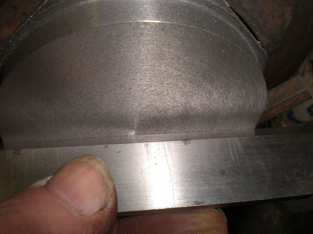
                Hi, as it happens, I faced up a piece of cast iron cut from an old bearing plummer block for an 80 mm 4 jaw. I found no significant out of flatness at all. First checked it with a straight edge.

                flatness check.jpg

                Then with a DTI and the error was not much more than the width of the pointer. This was done on my Boxford lathe.

                dti test 1.jpg

                dti test 2.jpg

                I'm wondering if SOD's back plate has become progressively harder from the inside to the outside during its manufacture for some reason, which could attribute to the concaving, just a thought.

                Regards Nick.

                #367235
                Hopper
                Participant
                  @hopper

                  Again, we need to be sure that we are clear that mounting a dial indicator on the toolpost or cross slide and then sweeping the pointer across the freshly faced surface does not give any indication whatsoever of flatness. The dial indicator is following the same path the cutting tool just took. So if the tool cut a surface with a 5mm dish in it, the dial indicator will follow the same path and show no deflection of the needle. (Providing gibs are tight, topslide is locked and no other random slop or movement is allowed.)

                  The straight edge test is good.

                  #367236
                  Chris Evans 6
                  Participant
                    @chrisevans6

                    I have one of those insert holders like the one SOD used to face the item. I only use it as a chamfering tool because the tip moves when trying to turn with it. My tool holder and tips are Sandvik so not a cheap set up of poor quality.

                    #367242
                    Michael Gilligan
                    Participant
                      @michaelgilligan61133
                      Posted by Hopper on 14/08/2018 01:53:09:

                      It seems like the best procedure would be to follow the usual one for machining a chuck backplate (or faceplate) and now that the main face has been roughed out, machine the thread and register surface so it can be screwed on to the lathe spindle for final machining of the face and OD.

                      .

                      I stand to be corrected, but: I think that would be 'a little tricky'

                      Dave appears to have one of these lathes: **LINK** … which are listed as having a flange fitting chuck.

                      https://www.warco.co.uk/metal-lathes-metalworking-lathe-machine/302996-wm280v-lathe.html

                      I am not aware [may have missed the disclosure] of the purpose of the job in hand, but I don't think it's just another regular backplate.

                      MichaelG.

                      #367258
                      Neil Wyatt
                      Moderator
                        @neilwyatt
                        Posted by Chris Evans 6 on 14/08/2018 07:35:06:

                        I have one of those insert holders like the one SOD used to face the item. I only use it as a chamfering tool because the tip moves when trying to turn with it. My tool holder and tips are Sandvik so not a cheap set up of poor quality.

                        Not cheap, but surely poor quality if the insert moves?

                        I don't have this problem with mine, which cost less than Sandvik.

                        Neil

                        #367265
                        blowlamp
                        Participant
                          @blowlamp
                          Posted by Hopper on 14/08/2018 07:33:46:

                          Again, we need to be sure that we are clear that mounting a dial indicator on the toolpost or cross slide and then sweeping the pointer across the freshly faced surface does not give any indication whatsoever of flatness. The dial indicator is following the same path the cutting tool just took. So if the tool cut a surface with a 5mm dish in it, the dial indicator will follow the same path and show no deflection of the needle. (Providing gibs are tight, topslide is locked and no other random slop or movement is allowed.)

                          The straight edge test is good.

                          As I've pointed out a few times, this is factually incorrect.

                          Martin.

                          #367266
                          Hopper
                          Participant
                            @hopper
                            Posted by Michael Gilligan on 14/08/2018 08:51:29:

                            Posted by Hopper on 14/08/2018 01:53:09:

                            It seems like the best procedure would be to follow the usual one for machining a chuck backplate (or faceplate) and now that the main face has been roughed out, machine the thread and register surface so it can be screwed on to the lathe spindle for final machining of the face and OD.

                            .

                            I stand to be corrected, but: I think that would be 'a little tricky'

                            Dave appears to have one of these lathes: **LINK** … which are listed as having a flange fitting chuck.

                            https://www.warco.co.uk/metal-lathes-metalworking-lathe-machine/302996-wm280v-lathe.html

                            I am not aware [may have missed the disclosure] of the purpose of the job in hand, but I don't think it's just another regular backplate.

                            MichaelG.

                            Ah well, once again we are groping around in the dark hazarding guesses at solutions to a problem on a job that has not been fully described. Presumably though, (and we all know about presumption!) it is some kind of chuck backing plate, as the OP says so. Either for this lathe, or for some other. Either way, the usual way to machine a chuck backing plate is to rough it out then place it in situ, be it on a threaded spindle or flanged, and do the final machining of the surfaces the chuck mounts to, so that the chuck mounting surface is true to the spindle axis.

                            #367268
                            Michael Gilligan
                            Participant
                              @michaelgilligan61133

                              yes

                              #367269
                              Farmboy
                              Participant
                                @farmboy
                                Posted by blowlamp on 14/08/2018 09:58:45:

                                Posted by Hopper on 14/08/2018 07:33:46:

                                Again, we need to be sure that we are clear that mounting a dial indicator on the toolpost or cross slide and then sweeping the pointer across the freshly faced surface does not give any indication whatsoever of flatness. The dial indicator is following the same path the cutting tool just took. So if the tool cut a surface with a 5mm dish in it, the dial indicator will follow the same path and show no deflection of the needle. (Providing gibs are tight, topslide is locked and no other random slop or movement is allowed.)

                                The straight edge test is good.


                                As I've pointed out a few times, this is factually incorrect.


                                Martin.

                                I suggest it would be correct only if the DTI is mounted in exactly the same position as the tool and is not run past the centre but, as you said previously, once you move the DTI beyond the centre you are measuring twice the deflection, as Dave appears to be doing in the photos in the original post. Unless, of course, the cross-slide guides are not straight, which seems unlikely dont know

                                Some of us were listening here at the back of the class wink 2

                                Mike.

                                Edited By Farmboy on 14/08/2018 10:43:28

                                #367273
                                Hopper
                                Participant
                                  @hopper
                                  Posted by blowlamp on 14/08/2018 09:58:45:

                                  Posted by Hopper on 14/08/2018 07:33:46:

                                  Again, we need to be sure that we are clear that mounting a dial indicator on the toolpost or cross slide and then sweeping the pointer across the freshly faced surface does not give any indication whatsoever of flatness. The dial indicator is following the same path the cutting tool just took. So if the tool cut a surface with a 5mm dish in it, the dial indicator will follow the same path and show no deflection of the needle. (Providing gibs are tight, topslide is locked and no other random slop or movement is allowed.)

                                  The straight edge test is good.


                                  As I've pointed out a few times, this is factually incorrect.


                                  Martin.

                                  Sorry, you are wrong in the context of the posted pic my post referred to.

                                  Mount the cross slide at an angle of 5 degrees from square and take a cut. The resulting surface will have an angle of 5 degrees from square. Now mount your dial indicator on the cross slide and sweep the plunger across the machined surface from rim to centre (as in the posted pic my post referred to). The dial indicator will register 0 all the way across (plus some minor variation for surface finish perhaps).

                                  Don't believe it? Go out in your workshop and try it.


                                  Edited By Hopper on 14/08/2018 10:55:38

                                  #367284
                                  blowlamp
                                  Participant
                                    @blowlamp
                                    Posted by Hopper on 14/08/2018 10:34:29:

                                    Posted by blowlamp on 14/08/2018 09:58:45:

                                    Posted by Hopper on 14/08/2018 07:33:46:

                                    Again, we need to be sure that we are clear that mounting a dial indicator on the toolpost or cross slide and then sweeping the pointer across the freshly faced surface does not give any indication whatsoever of flatness. The dial indicator is following the same path the cutting tool just took. So if the tool cut a surface with a 5mm dish in it, the dial indicator will follow the same path and show no deflection of the needle. (Providing gibs are tight, topslide is locked and no other random slop or movement is allowed.)

                                    The straight edge test is good.

                                    As I've pointed out a few times, this is factually incorrect.

                                    Martin.

                                    Sorry, you are wrong in the context of the posted pic my post referred to.

                                    Mount the cross slide at an angle of 5 degrees from square and take a cut. The resulting surface will have an angle of 5 degrees from square. Now mount your dial indicator on the cross slide and sweep the plunger across the machined surface from rim to centre (as in the posted pic my post referred to). The dial indicator will register 0 all the way across (plus some minor variation for surface finish perhaps).

                                    Don't believe it? Go out in your workshop and try it.

                                    Edited By Hopper on 14/08/2018 10:55:38

                                    What reading do you get if you sweep the plunger across the machined surface from rim to rim – still zero?

                                    #367292
                                    SillyOldDuffer
                                    Moderator
                                      @sillyoldduffer

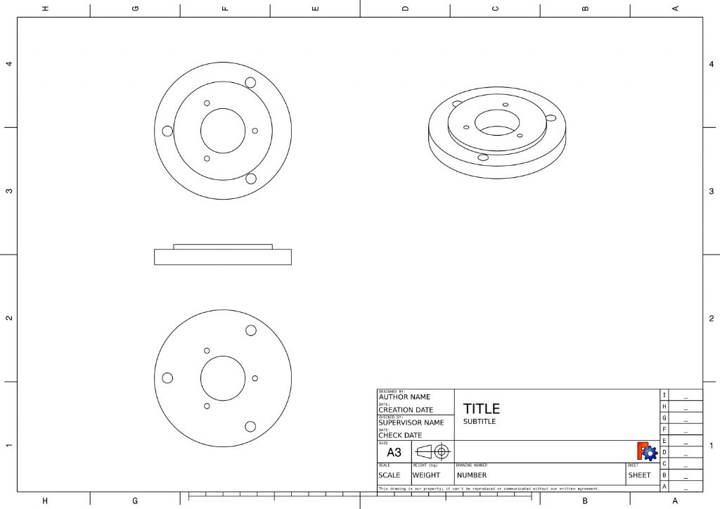
                                      Just a quicky for hopper, there's no secret about what I'm making – it's a chuck back-plate being made from a casting for the same lathe.

                                      chuckbackplate.jpg

                                      Not sure how to get FreeCAD to add dimensions to a generated drawing, but the plate is 160mm diameter and 18m thick.

                                      I don't think what it is makes much difference to the facing error, I could be facing anything. The way the casting was held in the chuck is more suspicious: although it felt firm, cutting pressure might have been rocking it.

                                      I've decided to finish the backplate and will re-open the investigation when I face off the other side. Got a number of suggestions to try.

                                      I'm hoping the issue is either:

                                      • the measurement is mistaken and the lathe is fine, or
                                      • that the cross-slide gibs are causing the cross-slide to move at a slight angle to the headstock and it's easy to fix.

                                      No conclusions yet, just clues, theories and suggestions. I need to investigate more methodically.

                                      Dave

                                      Edited By SillyOldDuffer on 14/08/2018 11:52:22

                                      #367293
                                      speelwerk
                                      Participant
                                        @speelwerk

                                        Gary Wooding in the posting "Lathe facing convex or concave" made a nice drawing of what the DTI is indicating. Sorry, no idea how to make a direct link to that posting so you have to look it up. Niko.

                                        #367294
                                        Journeyman
                                        Participant
                                          @journeyman

                                          Dave, I don't know whether that drawing is for the finished item but if so it does not show the register that mates with the lathe spindle. There should be a recess in the backside (about 52mm diameter an 4mm deep, if I remember correctly) which locates the chuck radially on the spindle.

                                          Perhaps I am looking at the drawing incorrectly and the hole through the middle is the register? I should have looked at my own backplate making effort first *** Collet Chuck *** DOHblush

                                          John

                                          Edit: 2nd Thoughts!!

                                          Edited By Journeyman on 14/08/2018 12:07:18

                                          #367296
                                          Michael Gilligan
                                          Participant
                                            @michaelgilligan61133
                                            Posted by speelwerk on 14/08/2018 11:52:21:

                                            Gary Wooding in the posting "Lathe facing convex or concave" made a nice drawing of what the DTI is indicating. Sorry, no idea how to make a direct link to that posting so you have to look it up. Niko.

                                            .

                                            Well-found, Niko

                                            Here's your prize : **LINK**

                                            https://www.model-engineer.co.uk/forums/postings.asp?th=93302

                                            Gary's drawing is on page 5

                                            MichaelG.

                                            Edited By Michael Gilligan on 14/08/2018 12:06:10

                                            #367314
                                            Hopper
                                            Participant
                                              @hopper
                                              Posted by blowlamp on 14/08/2018 11:19:11:

                                              Posted by Hopper on 14/08/2018 10:34:29:

                                              Posted by blowlamp on 14/08/2018 09:58:45:

                                              Posted by Hopper on 14/08/2018 07:33:46:

                                              Again, we need to be sure that we are clear that mounting a dial indicator on the toolpost or cross slide and then sweeping the pointer across the freshly faced surface does not give any indication whatsoever of flatness. The dial indicator is following the same path the cutting tool just took. So if the tool cut a surface with a 5mm dish in it, the dial indicator will follow the same path and show no deflection of the needle. (Providing gibs are tight, topslide is locked and no other random slop or movement is allowed.)

                                              The straight edge test is good.

                                              As I've pointed out a few times, this is factually incorrect.

                                              Martin.

                                              Sorry, you are wrong in the context of the posted pic my post referred to.

                                              Mount the cross slide at an angle of 5 degrees from square and take a cut. The resulting surface will have an angle of 5 degrees from square. Now mount your dial indicator on the cross slide and sweep the plunger across the machined surface from rim to centre (as in the posted pic my post referred to). The dial indicator will register 0 all the way across (plus some minor variation for surface finish perhaps).

                                              Don't believe it? Go out in your workshop and try it.

                                              Edited By Hopper on 14/08/2018 10:55:38

                                              What reading do you get if you sweep the plunger across the machined surface from rim to rim – still zero?

                                              It seems we are talking about two different things. I was talking about rim to centre, as in the posted photo I was referring to. You are talking about rim-to-rim.

                                              However, I re-read your earlier post about sweeping rim to rim. Yes, if the cross slide's path is consistent all along its length of movement, the dial indicator will read 0-0 from the front edge of the rim to centre, then if ithe cross slide continues on that same perfectly straight path, the indicator will then show double the error between centre and the rear edge of the rim. Assuming the cross slide travel is a perfectly straight line all the way through its movement, which it may or may not be.

                                              Sweeping the dial gauge across a known flat surface such as faceplate or a parallel strip held in the four jaw and set true gives a straight, true reference plane that the actual movement of the cross slide can be measured against. That's why it's the preferred method when scraping in the carriage ways etc to ensure the cross slide is square to the spindle axis.

                                              #367320
                                              Hopper
                                              Participant
                                                @hopper
                                                Posted by SillyOldDuffer on 14/08/2018 11:51:06:

                                                Just a quicky for hopper, there's no secret about what I'm making – it's a chuck back-plate being made from a casting for the same lathe.

                                                chuckbackplate.jpg

                                                Not sure how to get FreeCAD to add dimensions to a generated drawing, but the plate is 160mm diameter and 18m thick.

                                                I don't think what it is makes much difference to the facing error, I could be facing anything. The way the casting was held in the chuck is more suspicious: although it felt firm, cutting pressure might have been rocking it.

                                                I've decided to finish the backplate and will re-open the investigation when I face off the other side. Got a number of suggestions to try.

                                                I'm hoping the issue is either:

                                                • the measurement is mistaken and the lathe is fine, or
                                                • that the cross-slide gibs are causing the cross-slide to move at a slight angle to the headstock and it's easy to fix.

                                                No conclusions yet, just clues, theories and suggestions. I need to investigate more methodically.

                                                Dave

                                                Edited By SillyOldDuffer on 14/08/2018 11:52:22

                                                OK. So the backplate should be bolted to the flange and finish turned across the surfaces the chuck mounts to while in situ so the chuck ends up running true to the spindle axis. (Is there a spigot or register of some sort on the spindle flange side of the backplate to ensure it always runs concentric to the spindle?)

                                                If your facing cut is somewhat concave, it will not matter too much on the shown backplate. The chuck is located by the OD of the register step and the narrow flange of material outboard of that, which if slightly concave will not matter a whit. Chuck will locate on the outer area without rocking, which it would if the surface were convex.

                                                Hard to see how the blank could be loose enough to magically wobble around in a conical shape without falling out of the chuck all together, or at least jamming up the tool etc.

                                                If the cross slide is moving at an angle to the spindle axis, it might be a matter of cross slide gib adjustment, but it could also quite likely be a matter of the saddle sitting skewed on the bed, causing the cross slide dovetails to be skewed. Could be poor machining on the ways in the saddle, or wear, or just a bit of swarf in the wrong place.


                                                Edited By Hopper on 14/08/2018 12:57:59

                                                #367325
                                                JasonB
                                                Moderator
                                                  @jasonb

                                                  The hole in the backplate fits onto a 10mm or so long spigot that protrudes from the flange so the drawing is correct.

                                                  The raised register that is shown on te drawong is the usula register for a chuck, I assume a 160mm chuck from the size given.

                                                  I did mention early on that it was a flange mount plate and the cast boss would get turned away and stud holes drilled.

                                                  #367332
                                                  blowlamp
                                                  Participant
                                                    @blowlamp
                                                    Posted by Hopper on 14/08/2018 12:37:15:

                                                    Posted by blowlamp on 14/08/2018 11:19:11:


                                                    What reading do you get if you sweep the plunger across the machined surface from rim to rim – still zero?

                                                    It seems we are talking about two different things. I was talking about rim to centre, as in the posted photo I was referring to. You are talking about rim-to-rim.

                                                    However, I re-read your earlier post about sweeping rim to rim. Yes, if the cross slide's path is consistent all along its length of movement, the dial indicator will read 0-0 from the front edge of the rim to centre, then if ithe cross slide continues on that same perfectly straight path, the indicator will then show double the error between centre and the rear edge of the rim. Assuming the cross slide travel is a perfectly straight line all the way through its movement, which it may or may not be.

                                                    Sweeping the dial gauge across a known flat surface such as faceplate or a parallel strip held in the four jaw and set true gives a straight, true reference plane that the actual movement of the cross slide can be measured against. That's why it's the preferred method when scraping in the carriage ways etc to ensure the cross slide is square to the spindle axis.


                                                    I was talking about measuring the error the OP thinks he has when doing a facing cut.

                                                    The relationship of cross slide movement is not measured against the spindle axis, it's measured by perpendicularity to the lathe bed ways.

                                                    To this end, a reference fixture is mounted to the guiding surfaces of the bed and this fixture has a flat machined surface at 90 degrees to the bed ways.

                                                    When testing for correct movement of the cross slide, the finger of the DTI is run along the machined surface and adjustments are made until it's within specification. This gives proper 90 degree (nominal) movement to the cross slide/bed assembly.

                                                    The flat bar in the 4 jaw can suffer from inaccurate mounting, clamping distortion, or by the fact that the headstock axis is not parallel to carriage movement. It's good enough in many cases once the lathe is known to turn parallel, but you probably wouldn't want to use the method to casually check a lathe with a swivelling headstock.


                                                    Martin.

                                                    Edited By blowlamp on 14/08/2018 14:28:46

                                                    #367448
                                                    Hopper
                                                    Participant
                                                      @hopper
                                                      Posted by blowlamp on 14/08/2018 14:20:58:

                                                      The relationship of cross slide movement is not measured against the spindle axis, it's measured by perpendicularity to the lathe bed ways.

                                                      To this end, a reference fixture is mounted to the guiding surfaces of the bed and this fixture has a flat machined surface at 90 degrees to the bed ways.

                                                      Ultimately, maybe. But not practical in the average home workshop by the average duffer.

                                                      ISTR reading somewhere that the fixture method you mention was used at the Myford factory, in a production situation where making such a precision fixture was both possible and warranted.

                                                      The parallel bar mounted in the four jaw chuck is widespread standard practice. It is the recommended method in Ed Connelly's tome "Machine Tool Reconditioning", ie the bible on such matters. So I don't think there can be too much wrong with it. And of course, it is done after bed has been leveled and headstock spindle has been aligned to bed and proved with a turning test.

                                                    Viewing 25 posts - 51 through 75 (of 101 total)
                                                    • Please log in to reply to this topic. Registering is free and easy using the links on the menu at the top of this page.

                                                    Advert

                                                    Latest Replies

                                                    Home Forums Beginners questions Topics

                                                    Viewing 25 topics - 1 through 25 (of 25 total)
                                                    Viewing 25 topics - 1 through 25 (of 25 total)

                                                    View full reply list.

                                                    Advert

                                                    Newsletter Sign-up