Draper MD350 Naerok RDM350 New Owner Questions

Advert

Draper MD350 Naerok RDM350 New Owner Questions

Home Forums Manual machine tools Draper MD350 Naerok RDM350 New Owner Questions

Viewing 25 posts - 1 through 25 (of 35 total)
  • Author
    Posts
  • #713319
    Russell Talbot
    Participant
      @russelltalbot34770

      Hi Everybody

      I recently bought a Draper MD350 Mill Drill to replace a smaller variable speed mill.  This is a rebadged Naerok Mill with some Draper modifications.

      I was fed up with the little mill after replacing the motor two or three times and although I had added a thermal cut out and lower fuse values I had lost faith in it and wanted something more powerful and preferably with an induction motor.

      As a new owner of the Draper/Naerok there are a few things that I have questions about and I thought people here may be able to help.

      The first thing is the speed chart.  The sticker inside the belt cover has been peeled off and it came with a printed card with a speed chart.  The speeds are different to the pictures of the speed chart I have seen online?  Can anyone explain this?

      There is a sticker on the machine saying that Draper changed the switchgear to comply with a European standard. I was wondering what other modifications had been made.  There are signs that there was a lamp and a cut out switch on the belt cover.  Does anyone know what was fitted originally to the Naerok and the Draper?

      I’ve been thinking of fitting a DRO using a TouchDRO and an Android tablet (left over from the previous mill).  I would like to use glass scales on all three axes.  Does anyone have any suggestions or pictures on how to fit them?  I am inclined to fit the x-scale on the front of the table to avoid losing travel but at the moment I am scratching my head about the Z-axis.

      The mill I have bought is a metric machine – the dials are calibrated in tenths of millimetres. Has anyone tried making a vernier to help with setting dials?

      This machine has a crank at the bottom to move the column and head up and down and the head does not revolve as it is “keyed” by the rack.  When the column clamps are undone the head will move about 1.5mm in the x direction, presumably other people have tried shimming the rack to reduce that movement.  Can it be done successfully? What have people tried?

      The mill has an R8 taper and the drawbar doesn’t seem to need to be immensely tight but I don’t see any way of locking the spindle or even putting a spanner on it.  Does anyone have any suggestions?

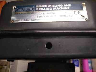
      And finally (for now), there is a hole in the front of lower part of the belt guard.  Does anyone have any idea what this might have been for. (picture)

      whatisthisholefor

      I’d be grateful for any help, I have some ideas but thought I’d see if there were any better ones to save me re-inventing the wheel (although of course the axle was the important part of the invention).

      Russell


      Advert
      #713347
      Diogenes
      Participant
        @diogenes

        The speed ranges of these generic mill/drills varied from make to make and model to model; low could be anything from 90 to about 200 and high from about 2000 to 2500, with usually 12 speeds on offer.

        Tony Griffiths has some information about the ‘family’ here;

        http://www.lathes.co.uk/sealey/

        http://www.lathes.co.uk/naerok-mill-drill/

        As regards ‘original equipment’ there is quite some difference in age between the first units and the later models and generally safety features were introduced only as a result of changes in legislation and ‘feature upgrades’ were rare – the very early Naeroks and Alpines were quite basic in terms of equipment, the later variants had guards, lock-outs, NVR switches and other safety features – it is possible that a manual for your particular Draper model is available on the net somewhere and that would show what the original equipment and fittings were.

        I have 3 glass scales on a Warco Major, with the X-scale on the front in the ‘stop’ slot, the Y scale off the L/H side with the read-head hanging from a bracket on the saddle – the Y takes careful setting up because of the irregularity of the base, but once you’ve got it all in alignment, I guess it’s in alignment for ever. The ‘Z’ is clamped to the side of the head with the read-head on brackets attached to a bar that replaces the depth-stop rod.

        I no longer have pictures available, but would put some in a gallery if you are interested – I would say that fitting a DRO to a mill is a complete game-changer and thoroughly recommended – it still is the best-spent money I have ever splurged on any accessory or measuring instrument.

        I hadn’t considered a vernier system for the dials – without giving it much thought I think for some things it would work well, for others be a complete disaster – I’m trying to picture how backlash might effect it – I suspect that in the heat of an actual cutting operation, it could be one demand too many on one’s attention – for critical stuff, stops / gauge rods / dial gauges / bigger scales might be better? ..or a DRO, then none of it matters..

        When tightening / loosening the drawbar on my Warco the rim of the pulley makes an adequate handhold to grip the spindle.

        I don’t know about the hole – if you suspect that the machine had a work-light at some point, that would seem a handy spot for a switch, especially if fitted by a former owner perhaps?

        #713668
        john fletcher 1
        Participant
          @johnfletcher1

          I’ve had a RDM 350 for 30 odd years and have carried out lots of mods to it, some following a series of articles in Model Engineer. I fitted a pre owned Inverter, and 3 PH motor, made my own controller box. So now I have on/off speed control and jog for setting up, no reverse. I threw out the pulley system, now one long link belt front to rear. You mention the slight movement when moving the head up/down, that is covered in the ME mod articles, which I think I could forward on you a copy. I’ve made a power cross feed using a car up/down window motor and small home made power supply, using small gears from a photo copier. Now I have for/rev, disengage, speed and fast travers. Not all windscreen wiper motors are reversible. My machine was pre owned, but I do have an instruction booklet, but its really all about a USA model. A DRO would certainly be an advantage but I’ve some how got round without it. Should you get around to fixing a DRO system please keep me posted. John

          #713686
          john fletcher 1
          Participant
            @johnfletcher1

            Back again after reading your message a second time. Re the R8 and draw bar. I hold the spindle with one hand and tighten up the draw bar as far as possible hand tight, then finish off with two spanners tightening up, not to much. There should be a fixed nut at the top of the draw bar (I welded it, after making it) and a movable one below Also forgot to mention I made a digital speed read out following an article in MEW, its fitted where the other one used to be.

            #713707
            ChrisLH
            Participant
              @chrislh

              I have a similar set up of key / rack on my Dore-Westbuty mill with the accompanying x play. I’ve never thought to do anything about it though, I just make sure that I push the spindle head to the right before tightening the collum clamps. No work is done with the clamps loose after all so the play does not matter.

              #713728
              old mart
              Participant
                @oldmart
                #713742
                Diogenes
                Participant
                  @diogenes
                  On old mart Said:

                  I bought one of the cheap laser digital hand held rpm meters.. … …

                  Yes, ditto..

                  #713830
                  Russell Talbot
                  Participant
                    @russelltalbot34770

                    Thank you for all the replies.

                    So far I have generally tightened the drawbar with the belt cover closed so it had never occurred to me to hold the pulley, and I had made my own drawbar and have never before seen one with two nuts, so there are two good ideas to start with.

                    I have made a bit of progress on speeds since my previous post by measuring all the pulleys and doing some sums.  There is some uncertainty because of the difference between diameter and pitch diameter (if that’s the right term) but my calculated values are within 1% of the values seen in photos of speed charts online.  They are nothing like the values in the printed chart that came with the mill.  I was wondering whether the original chart was wrong and someone had produced their own version but that now seems unlikely. Clearly measuring the speeds will give the definitive answers. The latest version of TouchDRO includes a tachometer and I have already built the electronics so I will probably make a sensor for that rather than buy a separate rev counter although I am grateful for the suggestion.

                    I’m still intending to fit the DRO scales.  I was hoping for any suggestions which might give me a clue as to how much extra length beyond the measuring length could be accommodated (other than the obvious answer of as little as possible).

                    As far as the rack/key goes I had been wondering about just pushing the head to the left (or right) when tightening and I am interested to see how effective that is, but I would be very interested to see the ME articles you refer to John.

                    I’m still curious about some of the original features and redundant holes I’ve found, just because I’m curious about everything.

                    Thanks again for the replies and advice.

                    Russell

                    #713833
                    duncan webster 1
                    Participant
                      @duncanwebster1

                      One idea I’ve read about for round column mills is to fix a laser pointer to the head and mark a vertical line on the opposite wall. I suspect mounting a long strip of mirror on the head and putting the laser on the opposite wall next to the vertical line would double the sensitivity, but how do you attach the strip of mirror? No idea. You wouldn’t need a line, just a target.

                      If you go down this road make sure you don’t get an eye full of laser

                      #713854
                      Michael Gilligan
                      Participant
                        @michaelgilligan61133

                        At the risk of stating the obvious: laser beams are great for alignment over relatively long distances … but, particularly at the ‘affordable’ end, the spot size and shape can limit their usefulness at shorter range.

                        Also … if using mirrors, remember that a ‘first surface’ version will be optically better.


                        Duncan’s wise warning about eye-safety is paramount

                        …. many of the cheap imported lasers are [rather unexpectedly] more powerful than their specification.

                        MichaelG.

                        #713858
                        Howard Lewis
                        Participant
                          @howardlewis46836

                          Stan Bray said that a cheap laser, over a distance of 10 feet would align within a thou.

                          I use a cheap, (B&Q) laser mounted on the head, over a distance of about 10 feet, to align on a pencil line on the wall, and have no problems with picking up holes again.

                          For safety, when not immediately needed, the laser is switched off, and I never look at it when it is on

                          Howard

                          #713866
                          Martin Connelly
                          Participant
                            @martinconnelly55370

                            I think worrying about the round column is over rated. Think about what you are doing before hand and a lot of moving the head during a machining operation is going to go away. If you can’t avoid it the usual problem is small mills or drills are short compared to larger milling cutters and drills. This can be overcome by using a Ø16 parallel shank ER16 collet chuck in a Ø16 collet. The smaller tool can then be lowered to the required location without moving the head. Lastly get a mini touch probe with a USB lead (search 3d CNC probe). These can be used with or without CNC as the USB powers an onboard LED that shows either red or green (changes on contact). Use this to re-acquire the X axis position after a head move, as you can ignore the Y axis error most of the time. Think of it like this, you move the head up or down and tighten it in about the correct position. The error in the X axis is maybe (at worst) about 3mm. Due to the small angle of rotation the Y axis error will be a function of the radius of the spindle about the centre of the column and the angle of the error. So it may be radius 300m and error 3mm and the angle of error is 0.57°. This will give a Y axis error of 0.015mm or 0.6 thou of an inch (Pythagoras). The mini touch probe will come in handy for other probing operations and can be powered from any USB supply including a small rechargeable battery type power bank.

                            Martin C

                            #713887
                            Michael Gilligan
                            Participant
                              @michaelgilligan61133
                              On Howard Lewis Said:

                              Stan Bray said that a cheap laser, over a distance of 10 feet would align within a thou. […]

                              I don’t doubt your word, Howard … but I would be grateful for some geometric clarification.

                              For a round column mill; we are obviously talking about [small] angular displacement

                              Therefore, surely we need to know at what radius from the centre of rotation this thou is being measured.

                              Two numbers are not enough to describe the geometry.

                              An actual reference to Mr Bray’s statement would be nice, but if you don’t recall it then please just pick a reasonable number.

                              Many thanks

                              MichaelG.

                              #713901
                              duncan webster 1
                              Participant
                                @duncanwebster1
                                On Howard Lewis Said:

                                Stan Bray said that a cheap laser, over a distance of 10 feet would align within a thou.

                                I use a cheap, (B&Q) laser mounted on the head, over a distance of about 10 feet, to align on a pencil line on the wall, and have no problems with picking up holes again.

                                For safety, when not immediately needed, the laser is switched off, and I never look at it when it is on

                                Howard

                                Just occurred to me, mirror on the wall and laser/target on the head. If the centreline distance of the mill spindle to column is say 10″ and distance to wall is 10 ft we then have a 24:1 amplification. Can you see a 0.024″ offset? Stan Bray knew what he was about, I’d trust him

                                #713903
                                Michael Gilligan
                                Participant
                                  @michaelgilligan61133

                                  So would I, Duncan … I was simply asking Howard to supply the missing number.

                                  MichaelG.

                                  #713907
                                  Michael Gilligan
                                  Participant
                                    @michaelgilligan61133

                                    Just to answer Duncan’s [possibly rhetorical] question:

                                    Yes, given some familiarity with the particular laser spot, 0.024” displacement should be quite noticeable … but with Howard not using a mirror 0.012” viewed on the distant wall would be trickier.

                                    It all comes down to the [optical lever] amplification, which is why I mentioned it.

                                    MichaelG.

                                    #713916
                                    john fletcher 1
                                    Participant
                                      @johnfletcher1

                                      Regarding the spindle speed I made a disc using copper clad pcb board using the rotatary table cut 60 teeth and followed the article in MEW. For the column you need Model Eng.21. December 1990 by G.F.A.M. Turners. Mr turner wrote several articles, you may find them on the web but if you are stuck send me a PM with your email address. His ideas have worked well for me. Details of the power cross feed power supply ME 21 Sept 1990. John

                                      #713924
                                      Russell Talbot
                                      Participant
                                        @russelltalbot34770

                                        Thank you for all the interesting laser suggestions.  I don’t think I’m going to go down that route but you never know…

                                        I have thought about it though.  It seems to me that using a mirror has the major advantage that you are close to the spot as you are moving the head so accuracy of half a mm or so should be achievable.  I think another advantage of a mirror would be that it wouldn’t be influenced by the column not being completely vertical but it would require the mirror to be precisely aligned with the column.  I was even wondering whether a convex (cylindrical) mirror would help but I think that would probably just make the dot wider.  My garage is about 16 ft wide so if I could find a suitable mirror and a clear bit of wall on which to mount it then 40:1 amplification should be achievable (given the 9″ column to spindle distance) – maybe even a bit more using the garage diagonal.  Less than 0.001″ error should be possible.

                                        I have done a similar calculation to Martin C about Y axis error.  I measured the x axis movement as 1.5mm and the column to spindle distance as about 225mm giving a y axis error of 0.005mm.

                                        John, PM sent, thank you.

                                        Thank you Martin for mentioning the mini touch probe, I hadn’t looked on line for touch probes, but I had considered making one as TouchDRO has an input for a probe.  I thought they’d be much more expensive.

                                        Thanks again.

                                        Russell


                                        #713932
                                        old mart
                                        Participant
                                          @oldmart

                                          The round column mill at the museum has had one of those laser gunsights on the side of the head for years. It reflects off a window about 12 feet away and back to the mill. The only downside of this is that the returned beam is about 3/16″ diameter, and I will replace the laser with one with better focus, one of the lasers in a small spirit level is better. When you buy one of these lasers, you have to take pot luck with the quality of the beam. I also think that a mirror might improve the optics rather than just a window. With care it is possible to keep to about +-0.001″ repeatability. Any mirror would need to have some fine adjustability in all axes.

                                          #713934
                                          Diogenes
                                          Participant
                                            @diogenes

                                            ..what is it that you want to know about DRO scales?

                                            #713936
                                            Michael Gilligan
                                            Participant
                                              @michaelgilligan61133

                                              Just for general background interest … Here is probably all that most will ever want to know about beam shaping:

                                              https://www.edmundoptics.co.uk/knowledge-center/application-notes/optics/laser-beam-shaping-overview/#:~:text=Laser%20diodes%20with%20no%20collimating,symmetric%2C%20compact%20final%20focused%20spots.

                                              .

                                              I have included the long link because it highlights their concise description of the fundamental problem with laser diodes [as distinct from proper, expensive, lasers]

                                              MichaelG.

                                              #713955
                                              old mart
                                              Participant
                                                @oldmart

                                                Useful information when trying to get a cheap laser to have a smaller beam. It might respond to some rotation of the lens if it is not optimally set up. As I said, another laser has a superior beam, but it will need modified fixing to the mill.

                                                #713976
                                                Martin Connelly
                                                Participant
                                                  @martinconnelly55370

                                                  If you have an old low capacity hard disk you do not want it probably has an aluminium alloy disk that can be used as a first surface mirror for a laser beam. They are also very flat.

                                                  Martin C

                                                  #714583
                                                  Howard Lewis
                                                  Participant
                                                    @howardlewis46836

                                                    With regard to the numbers, do the calulation based on the thickness of the laser line being the perpendicularof a triangle with the ten feet dimension as the base

                                                    If you accept the laser line as being 0.0625″ (probably an over estimate) wide at ten feet, the tangent of the angle is 5.2083′ x 10^ – 4, which would give an angular error of 0.0298 degrees, or 1.7 minutes of arc, from absolute accuracy.

                                                    Suffice to say that using my equipment, having moved the head up, and realigned using the laser, the drill enters the hole again without resistance, deflection or problem, every time.

                                                    In my rough book, that makes the pudding quite edible!

                                                    Howard

                                                    #714587
                                                    Michael Gilligan
                                                    Participant
                                                      @michaelgilligan61133

                                                      Thanks, Howard … although that doesn’t actually address my question 🙁

                                                      I wanted to know the distance [some number less than 10 feet] between the centre of the column and the centre of the quill. … It’s a matter of comparing ‘similar triangles’

                                                      MichaelG.

                                                      .

                                                      P.S. __ in my experience 0.0625” would be a very small spot for an affordable laser to produce at a distance of 10 feet … but you may have hit lucky.

                                                    Viewing 25 posts - 1 through 25 (of 35 total)
                                                    • Please log in to reply to this topic. Registering is free and easy using the links on the menu at the top of this page.

                                                    Advert

                                                    Latest Replies

                                                    Home Forums Manual machine tools Topics

                                                    Viewing 25 topics - 1 through 25 (of 25 total)
                                                    Viewing 25 topics - 1 through 25 (of 25 total)

                                                    View full reply list.

                                                    Advert