Determining/measuring sub-micron displacement

Advert

Determining/measuring sub-micron displacement

Home Forums Help and Assistance! (Offered or Wanted) Determining/measuring sub-micron displacement

Viewing 25 posts - 1 through 25 (of 46 total)
  • Author
    Posts
  • #592332
    Joseph Noci 1
    Participant
      @josephnoci1

      I posted in my CNC lathe thread a little on an edge finder/probe I am playing with. Turns out it is very sensitive in detecting contact with an object, but I wish to quantify that somehow. I wish to try measure the deflection of the ball at the instant where detection of the contact is made. A crude attempt in the DRO fitted mill gave very promising results, but not definitive. The DRO is a hi-spec glass scale type, with readout in 0.005mm resolution – note, not accuracy, just resolution. Moving the probe to detect contact, zero the DRO and then retract till no-detect and the DRO shows – nothing..no movement detected. I repeated this at a dozen different DRO positions, moving towards and away from contact, etc – the DRO never registers the movement that results in a detection or loss thereoff.

      I tried with a micrometer, screwing the anvil up to the ball till contact, and then retract till no contact – the amount of unscrew is so small it shows nothing on the micrometer scribed position line movement…

      I was wondering if Foucault measurement concepts ( such as for lens accuracies) might somehow be used – but not really applicable. My current ideas are around making a differential screw setup to improve on the micrometer concept – a differential screw with 1mm and 1.1mm pitches ) doable to some extent on my lathe with ELS, but at those dimensions maybe even the lathe leadscrew variation will mask the results. Averaging over a few settings of the differential screw length may help?  And even a 0.1mm per screw rev gives 0.001mm with 1/100 of a turn – difficult to determine that as well. – Maybe a combination of a metric and imperial thread, sort of 1mm and 1.01 mm pitch!

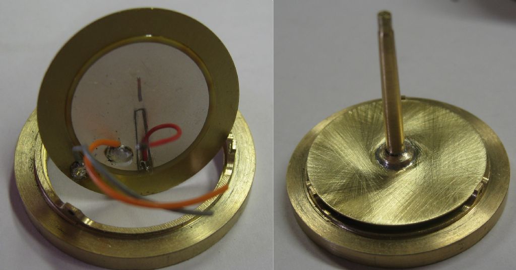
      The probe tip vibrates at around 3.9khz – in a resonant oscillator circuit, which relies on feedback from a pickup point on the piezo disc generating the mechanical vibration. The probe and disc are part of the mechanical load, setting the resonant frequency. A LC tuned circuit forms the 'tank' of the oscillator and ha a high circulating current in the tank ( tens of milliamps) . The feedback from the Piezo disc is adjusted so that the system only just oscillates. Then the slightest mechanical contact causes heavy damping of the resonant circuit, and oscillation stops – I then detect the drop in current in the coil and know we have made contact.

      How do I in an amateur workshop measure this? I guess I don't need to know that it is '0.3um' – sort of less than 1um would be good enough..!


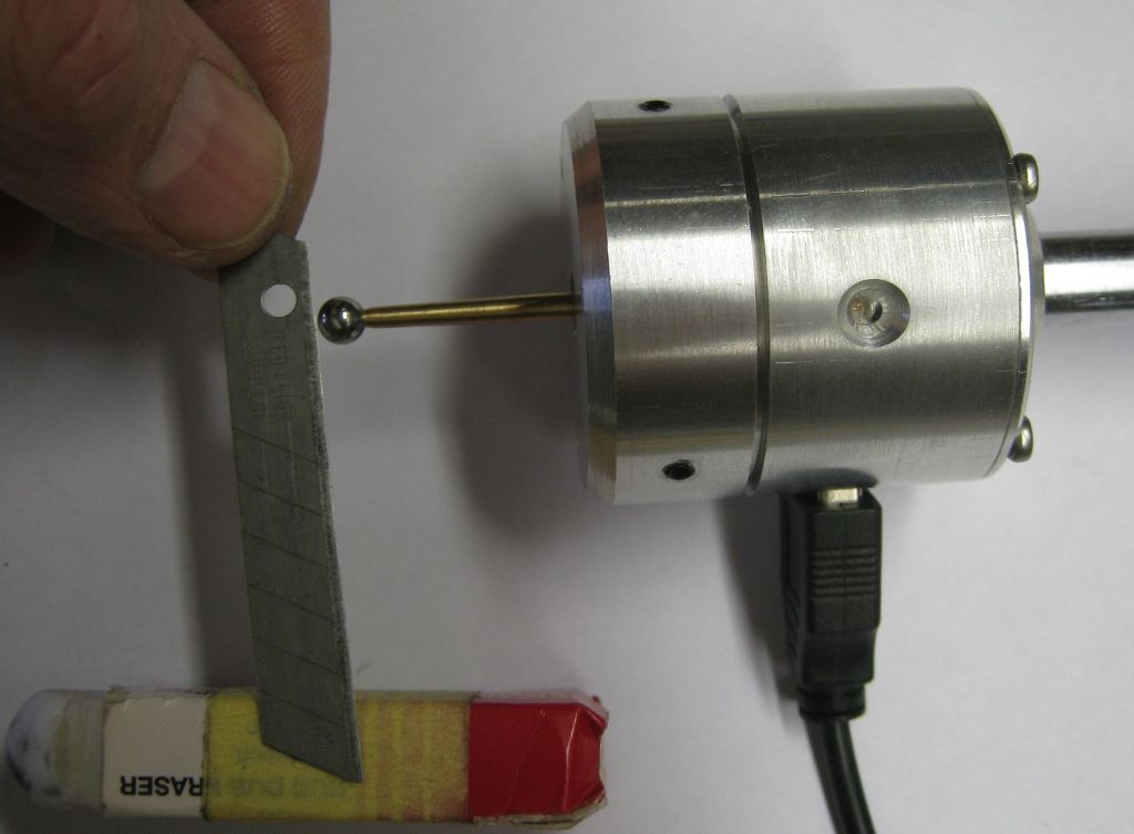
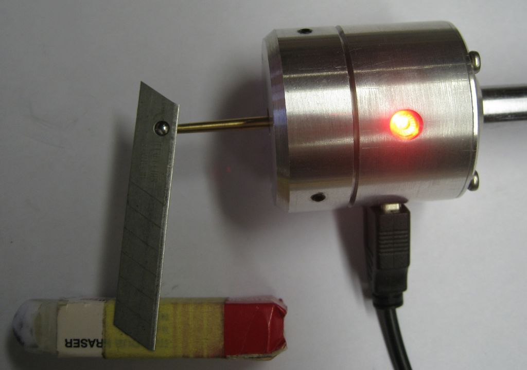
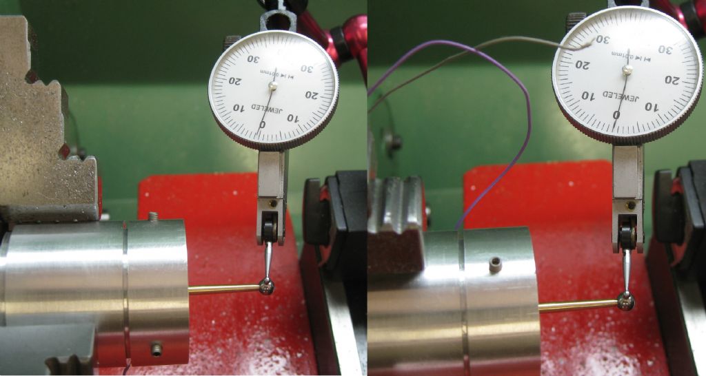
      0.4grams on the ball results in detection:

      no contact.jpg

      contact.jpg

      Piezo Disc showing the little feedback finger with red wire attached.

      piezo disc and holder.jpg

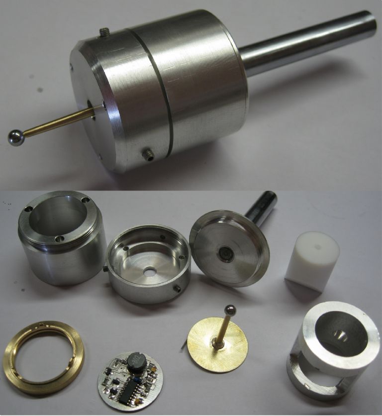
      total views.jpg


      Edited By Joseph Noci 1 on 01/04/2022 09:43:37

      Advert
      #34001
      Joseph Noci 1
      Participant
        @josephnoci1

        How to measure the displacement of the ball of an edge finder at edge detection

        #592337
        Kiwi Bloke
        Participant
          @kiwibloke62605

          I suppose you could start by investigating mechanical or optical amplification, the simplest that comes to mind would be a lever mechanism (causing and measuring the deflection at the 'long' arm) or a rotating mirror, with the scale a long way from the 'action'. The devil will be in the detail, so the pivot will have to be 'perfect' – a flexure, perhaps. Or research the mechanisms used for micro-manipulators. As you might expect, Dan Gelbart has a video which includes flexure-based micro-deflection mechanisms. Good luck: chasing microns is hard…

          #592339
          Michael Gilligan
          Participant
            @michaelgilligan61133

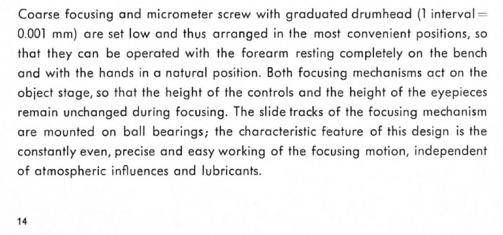
            Many of the decent optical microscopes from the middle years of the last century have focusing mechanisms graduated in one micron divisions … your stated requirement therefore seems relatively trivial, Joe

            MichaelG.

            #592345
            Joseph Noci 1
            Participant
              @josephnoci1

              Michael,

              The requirement in terms of your observation might seem trivial, but in the context on my final question, how to do this in my amateur setup, it still offers no solution other than perhaps purchasing such a mechanism – Not really a workshop solution?

              #592347
              KWIL
              Participant
                @kwil

                I am with Kiwi Bloke, many years ago I had to measure minute (and sometimes larger) deflections and used an optical "arm" some 20 feet long. Mirror illuminated by a slit source and projected onto a matt wall. Projected slit was a bit fuzzy by then but adequate for my application

                #592349
                duncan webster 1
                Participant
                  @duncanwebster1

                  Joseph Whitworth made a micrometer which could measure millionth of an inch. At least he said it could. Trying to back off a mic won't work due to backlash. I'd try something like a micrometer head with a very large thimble but spring loaded to take up backlash, and even then just advance it slowly to stop vibration, back off a tad, re-advance several times, but only take readings whilst advancing.

                  Edited By duncan webster on 01/04/2022 10:42:23

                  #592356
                  Andy_G
                  Participant
                    @andy_g
                    Posted by Joseph Noci 1 on 01/04/2022 09:39:37:

                    How do I in an amateur workshop measure this? I guess I don't need to know that it is '0.3um' – sort of less than 1um would be good enough..!

                    Mechanical dial indicators with a resolution on 0.001 mm are fairly widely available and have uses elsewhere – could you use one of them against the face that you're detecting with the probe? (Estimate to the half division?)

                    An interesting and ingenious project – as an aside, how do you ensure the concentricity of the probe to the holder?

                    #592357
                    Michael Gilligan
                    Participant
                      @michaelgilligan61133
                      Posted by Joseph Noci 1 on 01/04/2022 10:23:41:

                      Michael,

                      The requirement in terms of your observation might seem trivial, but in the context on my final question, how to do this in my amateur setup, it still offers no solution other than perhaps purchasing such a mechanism – Not really a workshop solution?

                      .

                      In all seriousness, Joe

                      I have a scruffy old Leitz Ortholux stand [just the bare mechanicals] which, if you can arrange collection, is yours for free. It is filthy dirty but I have just tried the fine focus mechanism and it works very smoothly.

                      Please contact me by message or eMail if I can help … but don’t dismiss the idea too quickly: it really would be the easy answer.

                      MichaelG.

                      #592360
                      Joseph Noci 1
                      Participant
                        @josephnoci1

                        Am looking into the optical route – a laser pointer with a pivoting mirror, etc – just not sure how to relate dot-on-the-far-wall displacement to the small mirror on a lever rotation, etc – seems like moving the measurement problem somewhere else is all…

                        Duncan, at first I also thought backlash was the issue – however it cannot be – screwing into contact with the ball is fine, then unscrewing, if there is backlash, should show greater thimble rotation than there actually is anvil travel. But that is not evident – During retraction contact detection is lost with no discernible graduation alignment movement on the thimble even with a loupe in the eye! If there was discernible graduation movement, then one could question the actual measurement since backlash would consume some of that linear movement.

                        I think Kiwi's excellent suggestion of flexures is the way to go – much easier to quantify the magnification ( or reduction) ratios, and driven by a micrometer drive gives the initial accuracy.

                        #592365
                        SillyOldDuffer
                        Moderator
                          @sillyoldduffer

                          Had to look up Foucault Lens Testing, not sure how it could be applied in this case.

                          Not thinking it through, my first reaction to Michael's microscope suggestion is there's a practical difficulty. How could a bulky microscope's objective lens get close enough to focus on the area of interest?

                          Of kiwi's amplifying suggestions, I think it would have to be purely optical because any mechanical arrangement is likely to spoil a delicate measurement. Friction, flexing, and the weight of the lever all count against it. Bouncing a laser on to a distant wall off a lightweight plane mirror glued to the probe should work.

                          Alternatively, could Joe use Jo-blocks? (Ho ho, ged it?) The method is a variant of what Joe has already tried with a micrometer, except Gauge Blocks are more accurate. Necessary to take multiple readings to average out the multitude of errors. As Joe has found, a micrometer doesn't have the necessary resolution, and it's screw thread is much more accurately made than the lead-screws found on machines.

                          For practical purposes, maybe all Joe needs to do is show that his electronic edge finder does a better job than the alternatives. Should be possible to measure the thickness of a cigarette paper and detect when a spinning cutter knocks it off. I guess a 2D mechanical edge finder is of similar accuracy, photo linked from ArcEuro's website:

                          Another thought. Use the edge finder to repeatedly detect a fixed corner, and then move the mill 10mm in X and Y to lightly dot a blued surface with a sharp needle point. The dispersion of the dots is a measure of repeatability, which depends on the accuracy of the edge finder and the lead-screws. The edge finder only needs to be more accurate than the lead-screws.

                          Does this make sense? Rude comments welcome!

                          Dave

                          #592376
                          Jeff Dayman
                          Participant
                            @jeffdayman43397

                            Hi Joe, An interesting application of simple flexures for high mechanical magnification in measurement was the Sigma comparator from 1930's or before. Relatively simple and robust and no expensive lenses etc in sight. Sub micron measurement with them is very possible depending on the magnification it is built with. A youtube video of the operating principles is linked below.

                            Johansson Mikrokator is also interesting, youtube link below. Higher magnification is possible with it too, if strip and needle are longer. As they get longer though, vibration from the building and people in it becomes a problem.

                            #592378
                            Robert Atkinson 2
                            Participant
                              @robertatkinson2

                              How about a sine bar on a surface plate and slip gauges or a micrometer head? Effectively a leaver of known length. The probe on top surface just past the center of the low end roller and gages under the other end. Possibly put the low roller in a V block to stop it moving.

                              otherwise stick a mirror on it and set up a laser interferometer. Not as hard as it sounds. Needs a helium neon laser, couple of mirror a beam splitter (microscope slide cover slip) bit of ground glass and a magnifier to see and count the fringes.

                              Robert G8RPI.

                              #592380
                              Pete Rimmer
                              Participant
                                @peterimmer30576

                                If sit a mirror on a bead of very soft silicone then bring the probe up to contact the mirror, an auticollimator will measure the amount the mirror tilts from the contact. You might be a to do the same by having an optical flat overhang the edge of a flat surface, and touch the flat with the probe.

                                #592394
                                Joseph Noci 1
                                Participant
                                  @josephnoci1
                                  Posted by Andy_G on 01/04/2022 10:52:38:

                                  Posted by Joseph Noci 1 on 01/04/2022 09:39:37:

                                  How do I in an amateur workshop measure this? I guess I don't need to know that it is '0.3um' – sort of less than 1um would be good enough..!

                                  Mechanical dial indicators with a resolution on 0.001 mm are fairly widely available and have uses elsewhere – could you use one of them against the face that you're detecting with the probe? (Estimate to the half division?)

                                  An interesting and ingenious project – as an aside, how do you ensure the concentricity of the probe to the holder?

                                  Andy_G : I have a Chinese 0.001mm indicator, but it is not great. The spring is quite weak, and there is a 'lube' in the pushrod tube that causes stiction so its presently useless..I have stripped it and its soaking in alcohol…Hopefully it is improved once assembled and will give it a try. The concentricity ( going to be another measurement problem – the probe can only be set as good as the measuring indicator..!) is set by means of 3 grub screws – see photo.

                                  Can be set very close to null – the bigger problem is how to drill the hole in the ball on the probe tip – if that is off axis, its a mess..

                                  setting runout.jpg

                                  #592395
                                  Joseph Noci 1
                                  Participant
                                    @josephnoci1
                                    Posted by Michael Gilligan on 01/04/2022 10:56:58:

                                    In all seriousness, Joe

                                    I have a scruffy old Leitz Ortholux stand [just the bare mechanicals] which, if you can arrange collection, is yours for free. It is filthy dirty but I have just tried the fine focus mechanism and it works very smoothly.

                                    Please contact me by message or eMail if I can help … but don’t dismiss the idea too quickly: it really would be the easy answer.

                                    MichaelG.

                                    Thank You for your Kind offer Michael. I would really like to take you up on it, but shipping tween Nam and the World is so expensive – Unless by 'mail' and a lot of that sort of mail parcel is simply 'lost' in Johannesburg – So I tend to only use Fedex/DHL air ship – a 1kg parcel from London to me is around 120 BP…

                                    Thank You…

                                    Joe

                                    #592396
                                    Michael Gilligan
                                    Participant
                                      @michaelgilligan61133

                                      You’re welcome, Joe … Sorry it’s not going to be viable

                                      I was sorta-hoping that you might have a convenient route available.

                                      MichaelG.

                                      #592404
                                      Howard Lewis
                                      Participant
                                        @howardlewis46836

                                        Sub micron suggests some form of optical measurement to me, such interference patterns

                                        The sort of dimension that changes as you breathe near it!

                                        After all, 0.001" is 25.4 microns (One third of the thickness of blonde human hair) and you are looking to measure less than 1/25th of that.

                                        Howard

                                        #592430
                                        Joseph Noci 1
                                        Participant
                                          @josephnoci1

                                          Played a bit in the workshop with this again. It will not be possible for me to measure accurately the actual deflection required for detection – as Kiwi Bloke said – chasing microns is hard! just brushing against the test setup causes detection to come and go in my setup – micron(s) are really small!

                                          I put the probe in the 3jaw on my Emco V10P. Gently clamped a micrometer in the tool post and tried with the anvil against the ball to see in a 'rigid' setup if I can actually see any movement of the thimble line from zero.

                                          The lightest touch on the thimble is enough to cause/remove detection, and being very gentle, holding my breath, I can 'just' sense some thimble rotation to make/break detection, but cannot see any line movement on the thimble with a x3.5 loupe.

                                          I moved the cross slide so that the micrometer anvil just touches the ball and shows contact, and locked all slides – fiddly to lock cross slide while ensuring that contact is 'just' made, but got it right. Then I 'tapped' my right forefinger nail against the tool post and each tap would break contact, removing finger re-made contact – the lightest of taps! See the video link…

                                          I have a strong suspicion the contact detection deflection is WELL into the sub-micron region!

                                          Testing contact sensitivity on the touch probe

                                          #592438
                                          Howard Lewis
                                          Participant
                                            @howardlewis46836

                                            Maybe using the ball as a contact bin an electrical circuit would give sufficient accuracy;m assuming bthat the contacts remain as clean every time for consistency of contact pressure?

                                            Howard

                                            #592463
                                            Joseph Noci 1
                                            Participant
                                              @josephnoci1

                                              Howard,

                                              Yes, that would confirm the moment of contact detection, but still not give an indication of any related ball deflection. Its a little complicated in this instance since the ball is oscillating in a rough sphere @ 3.9khz, so electrical contact will occur at the same time as oscillation damping – but I would still not have determined if there was any deflection of the ball, and how much…

                                              I am building a 20:1 reduction lever to be actuated by a micrometer and see if I can find my microns that way!

                                              #592469
                                              Michael Gilligan
                                              Participant
                                                @michaelgilligan61133
                                                Posted by Howard Lewis on 01/04/2022 15:57:58:

                                                Sub micron suggests some form of optical measurement to me, such interference patterns

                                                The sort of dimension that changes as you breathe near it!

                                                After all, 0.001" is 25.4 microns (One third of the thickness of blonde human hair) and you are looking to measure less than 1/25th of that.

                                                Howard

                                                .

                                                As I said earlier, Howard … In the context of Joe’s requirement, the measurement is trivial and can be easily achieved with seventy year old mechanisms.

                                                It is perhaps not intuitively obvious, but: whilst measuring a metre to +/- half a micron may be difficult, measuring a millimetre to to +/- half a micron is easy.

                                                MichaelG.

                                                .

                                                Edit: __ This is the model of instrument whose basic stand I was offering to Joe

                                                f35a3da7-fdb2-4575-b077-01d750c7dce7.jpeg

                                                .

                                                930d76ec-532d-4d5a-82e4-49610ee02abe.jpeg

                                                Edited By Michael Gilligan on 01/04/2022 21:33:32

                                                #592471
                                                old mart
                                                Participant
                                                  @oldmart

                                                  I have a microscope slide with divisions calibrated in 10 microns, with that I could probably get to a tenth of a micron under magnification.

                                                  #592476
                                                  Michael Gilligan
                                                  Participant
                                                    @michaelgilligan61133

                                                    Meanwhile … This is non-trivial in terms of price, but it is a stock commercial item: **LINK**

                                                    https://www.thorlabs.com/newgrouppage9.cfm?objectgroup_id=9862&pn=PFM450E

                                                    Check the specification surprise

                                                    MichaelG.

                                                    #592521
                                                    Kiwi Bloke
                                                    Participant
                                                      @kiwibloke62605

                                                      The more I think about this problem, the worse it seems. I think the problem of achieving a tiny, known, controlled displacement has many similarities to measuring such a displacement. After all, a micrometer measures by producing displacement.

                                                      But there's really difficult, more fundamental problem, which, until solved, prevents further progress. How does one detect the initial contact of probe to surface, as the probe advances, before the electronic detection occurs?

                                                      It gets worse: for the probe to produce meaningful results, its ball-end's diameter must be known (presumably to sub-micron accuracy), as well as the amplitude of its vibration at the times when electronic detection occurs, as well as at initial contact. In other words, the envelope produced by the vibrating ball's surface must be known (again to sub-micron accuracy). Also, to be useful in practice (to sub-micron accuracy), the centre of the ball must be aligned with the machine spindle to sub-micron accuracy. And then there are the standard metrology bugbears of the effects of temperature, air movement, surface contamination, gravity, etc., etc.. It's a horrible collection of problems!

                                                      I still think that optical methods might be able to solve more of the problems than purely mechanical methods, but it sounds like very large magnification would be required, so microscopy might be out (oil-immersion objectives don't sound practicable here). What about projection methods?

                                                      I know little about electronics, however, a feedback system is described. Can the feedback sensor's signal be used to, for instance, detect initial contact, before resonant vibration is damped by heavier contact? One might hope that the hard ball, clattering against a stiff-enough surface, at initial contact, might produce an albeit tiny, detectable signal, or at least distort (clip?) the feedback signal's waveform.

                                                      I can think of other problems, but it seems bad enough already. Glad it's not my problem… Most impressive – good luck!

                                                    Viewing 25 posts - 1 through 25 (of 46 total)
                                                    • Please log in to reply to this topic. Registering is free and easy using the links on the menu at the top of this page.

                                                    Advert

                                                    Latest Replies

                                                    Viewing 25 topics - 1 through 25 (of 25 total)
                                                    Viewing 25 topics - 1 through 25 (of 25 total)

                                                    View full reply list.

                                                    Advert

                                                    Newsletter Sign-up